1234567891011121314151617181920212223242526272829303132333435363738394041424344454647484950515253545556575859606162636465t413 k2 Vo(1)ok1wgwhere k 1 & k 2 are empirical coefficients (1.14 & 1.45 respectively, after Fay (1971)), V o is <strong>the</strong>original volume of <strong>spill</strong>ed <strong>oil</strong> (m 3 ), υ w is <strong>the</strong> kinematic viscosity of water (m 2 /s), g is gravitationalacceleration (m/s 2 ), <strong>and</strong> w is <strong>the</strong> relative density difference between water <strong>and</strong> <strong>oil</strong> given by:w <strong>oil</strong> (2)where ρ w is <strong>the</strong> density of water (g/cm 3 ) <strong>and</strong> ρ <strong>oil</strong> is <strong>the</strong> density of <strong>oil</strong> (g/cm 3 ). <strong>The</strong> area (m 3 ) overwhich <strong>the</strong> <strong>oil</strong> slick has spread at <strong>the</strong> end of this first spreading phase was determined by Fay (1971)<strong>to</strong> be:Ao4 5k 2Vog 2(3)k1 w2<strong>The</strong> second stage of slick spreading known as <strong>the</strong> gravity-viscous phase is governed by <strong>the</strong> balancebetween <strong>the</strong> viscosity of <strong>the</strong> <strong>oil</strong> <strong>and</strong> <strong>the</strong> <strong>oil</strong>-water interfacial tension. <strong>The</strong> viscous spreading phasecontinues <strong>to</strong> such a time that <strong>the</strong> slick gets so thin that surface tension forces alone play a role inspreading <strong>the</strong> slick, leading <strong>to</strong> <strong>the</strong> third, surface-tension, phase. This third phase is not <strong>model</strong>led in<strong>OILTRANS</strong> as it occurs at much later stages in slick spreading, ra<strong>the</strong>r a terminal <strong>oil</strong> film thicknessis defined in <strong>OILTRANS</strong> <strong>to</strong> denote <strong>the</strong> end of <strong>the</strong> gravity viscous phase after which no fur<strong>the</strong>rmechanical spreading occurs. Generally, by this time significant wea<strong>the</strong>ring will have occurred <strong>and</strong><strong>the</strong> slick is allowed <strong>to</strong> disperse horizontally or break in<strong>to</strong> smaller slicks due <strong>to</strong> surface currentshears.<strong>The</strong> general spreading formulae proposed by Fay (1971) only deal with an idealised spreading of aslick in a radial manner on calm seas. <strong>The</strong>y take no account of wind conditions, which play animportant role in determining <strong>the</strong> shape <strong>and</strong> area of actual <strong>spill</strong>s. Results of field experiments on <strong>the</strong>spreading of <strong>oil</strong> slicks have been reported by Elliott et al. (1986), Jeffrey (1973) <strong>and</strong> Lehr et al.(1984), all of which found that slicks developed elongated shapes, with <strong>the</strong> major axis orientated in<strong>the</strong> direction of <strong>the</strong> wind. Lehr et al. (1984) devised a Fay-type formula <strong>to</strong> account for <strong>the</strong>elongation of <strong>the</strong> <strong>oil</strong> slick in <strong>the</strong> direction of <strong>the</strong> wind.Using <strong>the</strong> assumptions adopted by previous researchers (Al Rabeh et al., 2000; Chao et al., 2003;Gou <strong>and</strong> Wang, 2009; Inan <strong>and</strong> Balas, 2010, Nagheeby <strong>and</strong> Kolahdoozan, 2008), that <strong>the</strong> slick iselliptical in shape with <strong>the</strong> major axis orientated in <strong>the</strong> direction of <strong>the</strong> wind, <strong>the</strong> area, A (x10 3 m 2 ),of <strong>the</strong> <strong>oil</strong> slick once <strong>the</strong> gravity-viscous spreading phase has commenced, can be represented as:A 1 QR4(4)where Q <strong>and</strong> R are <strong>the</strong> lengths of <strong>the</strong> minor <strong>and</strong> major ellipse axis respectively, given by :
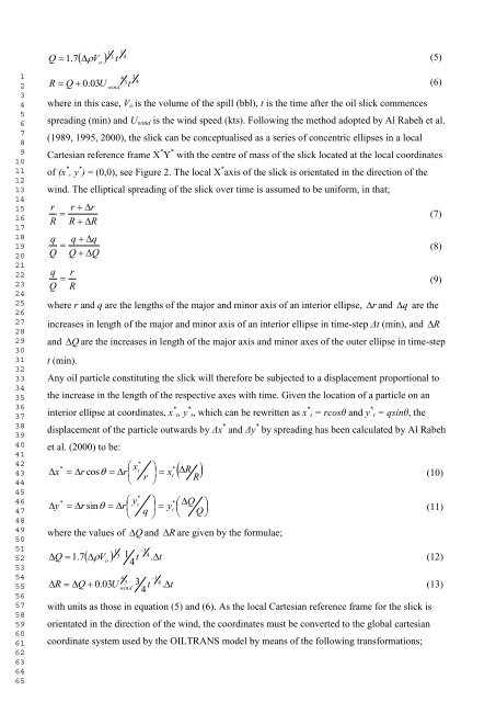
123456789101112131415161718192021222324252627282930313233343536373839404142434445464748495051525354555657585960616263646514V 1 3Q 1.7t(5)o43wind34R Q 0.03Ut(6)where in this case, V o is <strong>the</strong> volume of <strong>the</strong> <strong>spill</strong> (bbl), t is <strong>the</strong> time after <strong>the</strong> <strong>oil</strong> slick commencesspreading (min) <strong>and</strong> U wind is <strong>the</strong> wind speed (kts). Following <strong>the</strong> method adopted by Al Rabeh et al.(1989, 1995, 2000), <strong>the</strong> slick can be conceptualised as a series of concentric ellipses in a localCartesian reference frame X * Y * with <strong>the</strong> centre of mass of <strong>the</strong> slick located at <strong>the</strong> local coordinatesof (x * , y * ) = (0,0), see Figure 2. <strong>The</strong> local X * axis of <strong>the</strong> slick is orientated in <strong>the</strong> direction of <strong>the</strong>wind. <strong>The</strong> elliptical spreading of <strong>the</strong> slick over time is assumed <strong>to</strong> be uniform, in that;rRqQr r (7)R Rq q (8)Q Qq r (9)Q Rwhere r <strong>and</strong> q are <strong>the</strong> lengths of <strong>the</strong> major <strong>and</strong> minor axis of an interior ellipse,r<strong>and</strong> q are <strong>the</strong>increases in length of <strong>the</strong> major <strong>and</strong> minor axis of an interior ellipse in time-step Δt (min), <strong>and</strong><strong>and</strong>t (min).Qare <strong>the</strong> increases in length of <strong>the</strong> major axis <strong>and</strong> minor axes of <strong>the</strong> outer ellipse in time-stepAny <strong>oil</strong> particle constituting <strong>the</strong> slick will <strong>the</strong>refore be subjected <strong>to</strong> a displacement proportional <strong>to</strong><strong>the</strong> increase in <strong>the</strong> length of <strong>the</strong> respective axes with time. Given <strong>the</strong> location of a particle on aninterior ellipse at coordinates, x * t, y * t, which can be rewritten as x * t = rcosθ <strong>and</strong> y * t = qsinθ, <strong>the</strong>displacement of <strong>the</strong> particle outwards by Δx * <strong>and</strong> Δy * by spreading has been calculated by Al Rabehet al. (2000) <strong>to</strong> be:xy*** x r rt* cos x Rr t R(10)* y r rt *sin y Q qt Q(11)where <strong>the</strong> values of1 3V 3 1 t . tQ<strong>and</strong> Rare given by <strong>the</strong> formulae;4Q 1.7o(12)44 13R Q U 3 40.03windt . t4with un<strong>its</strong> as those in equation (5) <strong>and</strong> (6). As <strong>the</strong> local Cartesian reference frame for <strong>the</strong> slick isorientated in <strong>the</strong> direction of <strong>the</strong> wind, <strong>the</strong> coordinates must be converted <strong>to</strong> <strong>the</strong> global cartesiancoordinate system used by <strong>the</strong> <strong>OILTRANS</strong> <strong>model</strong> by means of <strong>the</strong> following transformations; R(13)