
Create successful ePaper yourself
Turn your PDF publications into a flip-book with our unique Google optimized e-Paper software.
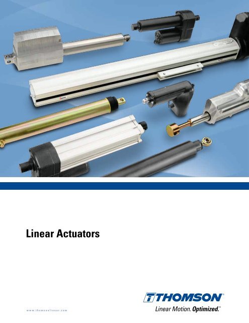
<strong>Linear</strong> <strong>Actuators</strong>w w w . t h o m s o n l i n e a r . c o m
IntroductionCompany IntroductionThe history of the Thomson Electrak ® actuator goes back to the developmentof ball screw actuators 40 years ago in Marengo, IL, USA. The first generationof general purpose actuators were developed for control of accessory driveson garden tractors and farm equipment. Since that simple beginning, actuatorsare now used in all types of equipment to automate a process, remove peoplefrom dangerous situations, provide remote control or make difficult, tediousmanual jobs easier.The linear actuators in this catalog represent provendesign concepts found in the entire Electrak series. Fromlight load 050s to the high performance Electrak Pro seriescapable of handling loads up to 1000 pounds,Thomsonoffers features unavailable anywhere else.The world’s most versatile actuator selectionThomson combined the clevis to clevis mount Electrakseries, and the trunnion mount Electrak PPA units, toprovide the most versatile selection of linear actuatorsavailable. Our actuator team has solved over 10000 toughapplication challenges with even tougher actuators. Webuilt our reputation in the mobile off highway market inextremely demanding operating conditions. And if youcan’t find the actuator to meet your application, call usfor a cost effective actuator built to your needs. Thomsonbuilds more custom actuators than anyone.You can count on ThomsonThomson linear actuators – rugged, reliable remote linearmotion control with the push of a button. You can count onThomson for worldwide sales, service, application supportand local availability. Please visit www.danahermotion.com for more information.1967 1969 1974 1982 1984 1987 1988 1991The firstgeneration ofactuators foruse in gardentractors andfarm equipmentis released.First line of ballscrew drivenactuators withright angle ACand DC motors isreleased.First line ofactuators withparallel motorsand bothacme and ballscrew drive isreleased.The “Tiger” lineactuators arereleased forOEMs.Electrak 1, 2, 5,10 and 100 arereleased fordistribution.Electrak 205and the firstline of MCScontrols arereleased.Electrak 1SPwith feedbackpotentiometeris released.The first liftingcolumns, DMDand DMA, arereleased.4 www.thomsonlinear.com
<strong>Linear</strong> <strong>Actuators</strong>IntroductionProduct IntroductionThomson actuators are easy to mount and operate, require no maintenance,don’t leak hydraulic fluid, are easy to incorporate into an automated processand once installed they will work reliably under the toughest conditions yearafter year.<strong>Actuators</strong> offer advantages over mechanical and hydraulicsystems in many applications. They are self-contained,rugged, and durable, making them ideal anywhere youwant to lift, lower, push, pull, rotate or position a load.Compact designWith their compact size, actuators can be located inconfined areas. An actuator with a 4 inch stroke lengthcan produce 1500 pounds of force from a 12 inch package.Electrak 1 and 050 series actuators fit small areas withpackage lengths as short as 6 inches.Rugged and reliableAll Thomson actuators incorporate strong, high qualitycomponents to assure trouble-free service. Rugged spur,worm or helical gearing, aircraft quality lubricants and highperformance motors provide the maximum life and value.The actuators are gasketed and sealed throughout forprotection in wet, dirty and oily environments and are idealfor use on outdoor equipment. The rod style actuatorshave stainless steel or aluminum extension tubes to resistcorrosion.Maintenance-freeAll adjustments and lubrication are made at the factoryand no maintenance is required or recommended.Consistent, repeatable performance is provided for theentire lifetime of the actuator.BidirectionalThomson actuators can push and pull loads ranging fromone pound to 3/4 ton, and can extend up to 36 inches. Withthe Thomson series of actuator controls, you can createan actuator control system to meet your particular motioncontrol requirements.Safe operationMotors used on Electrak actuators utilize thermal switchesin their windings or Electronic Load Monitoring to shut theactuator off in case of overheating. A standard overloadclutch or Electronic Load Monitoring will stop the motionif the load is too great or at the end of a stroke. All linearactuators will hold their loads with power removed.VersatileStroke lengths of 1 to 36 inches are available and speedsare as high as two inches per second. <strong>Actuators</strong> areeasy to apply, quick to install and usually only requiringtwo wires for operation. A wide variety of options andcontrols makes it easy to find the perfect actuator for yourapplication. And if you have special needs, cost effectivecustom solutions are our speciality.1992 1994 1998 1999 2000 2004 2006A patent for aload lock deviceis granted.Electrak 1LL isreleased.Electrak 150 withtwo patents isreleased. ACcontrol line isreleased.Electrak 050 withpatented designand the firstrotary actuatorsare released.The first LM80rodless actuatoris released.The triple profilelifting columnTC16 and the“sweeper“actuator arereleased.The Electrak Proactuator lineand the DCGcontrol line arereleased.www.thomsonlinear.com5
IntroductionThe Benefits of ElectrificationElectrification is converting manual, hydraulic and pneumatic operations toelectromechanical motion. Substantially improved machine performanceand cost advantages can be gained through electrification.Reduce costs• Electric actuation components cost less thancomparable hydraulic and pneumatic systems.• One electric linear actuator is faster and easierto install than the multiple hydraulic and pneumaticcomponents required to achieve the same function.• Electric actuators feature quick and predictable systemtuning when compared to the headaches of configuringhydraulic systems and their components which contendwith power variation, temperature variation, and nonlinearperformance profiles.• Compare zero maintenance electric actuators againstthe fluid replacement, leak repairs and other routinemaintenance needed to support hydraulic systems.• Eliminate the environmental problems and costsassociated with hydraulic fluid leaks and fluid disposal.Boost productivity and efficiency• Improve control over critical machine operations with:- Multiple digital and analog feedback options- Fixed and programmable limit switches for “teach andrepeat” positions- Low voltage switching options that can interfacedirectly with programmable PC/PLC controllers- Pulse width modulation for variable speed control• Superior accuracy and repeatability• Link and automate simultaneous processes• Reduce down time with:- Zero maintenance- Longer component life- Redundancy through manual override• Improve safety and reduce costs by removing peoplefrom danger with convenient remote controlGreat opportunities for electric conversion.Making jobs easier• Raising and lowering a deck on a mower, paver or floor scrubber.• Shifting manual transmission.• Lifting wheelchairs into a vehicle.• Opening and closing doors on buses or vans.Automating a process• Moving twine across a round bale of hay for consistent wrap.• Varying the chute opening on a salt/sand spreader based on speedfor consistent application.• Lift and lower pantographs on electrical trains and trams.Providing remote control• Throttle control from the rear of garbage trucks.• Positioning the discharge spout on a large chipper, snowblower orcombine.• Opening a chute on a salt/sand spreader.• Positioning of solar energy panels and wind power plant turbines.• Opening/closing the engine hatch on boats.• Positioning boat, handicap vehicle seats.• Belt tensioning.Removing people from danger• Sliding a cover over the stairs in a recreational vehicle.• Throttle control for a tree stump grinder to keep the operator awayfrom moving parts or flying debris.• Medical waste/refuse compacting.Replacing hydraulics or pneumatics• Power steering.• Dump beds on ATVs.• Positioning mower decks on golf course equipment.6 www.thomsonlinear.com
<strong>Linear</strong> <strong>Actuators</strong>IntroductionThe Benefits of ElectrificationReplacing hydraulic or pneumatic cylinders with electrical linear actuatorsmeans a simpler and smaller installation, easier control, lower energy costs,higher accuracy, less maintenance, less noise and a cleaner, healthierenvironment.432516Single acting, uni-directional hydraulic cylinder system1. Hydraulic cylinder2. Electric pump motor3. Hydraulic pump4. Hydraulic oil resevoir5. Check valve6. Operator push button box7. Relay cabinet8. Unloading valve7You can design, purchase and install all these componentsor you can select and install an actuator and switch.Plug and play type of connections, simple installation andno need for any set up or adjustments ensures accurate,clean and trouble free operation within the hour.182This single acting, uni-directional hydraulic cylinder systemis one of the simplest hydraulic solutions. This system onlyallows consistent performance in one direction. In orderto get consistent performance in both directions a bidirectionalsystem would be required which is even morecomplex and costly.Electric linear actuator system1. <strong>Linear</strong> actuator2. DPDT switchThis simple electrical actuator system will ensureconsistent operation in both directions. It will also giveyou added features such as electronic load monitoring,end of stroke limit switches, mid stroke protection andmanual override operation in case of power failure.Optional features such as analog or digital positionfeedback, adjustable end of stroke limit switches, end ofstroke indication outputs and signal following capabilityare also available. Another advantage is that a systemlike this is easy to integrate with other control systemsnormally found in industrial systems or vehicles such asPLC’s, micro-controllers, computers or simple relay basedsystems.www.thomsonlinear.com7
IntroductionActuator ApplicationsThomson Electrak actuators can be found in the most diverse applications,ranging from agricultural to industrial, ventilation and medical equipment.Anywhere you want to lift, lower, push, pull, rotate or position a load - onlyyour imagination will set the limit.Mobile-off-highway<strong>Actuators</strong> are widely used in agricultural, construction,mining, forestry, road work and railway equipmentfor the control of seats, hoods, doors, covers, balers,pantographs, sprayer booms, throttles and much more.Turf and garden<strong>Actuators</strong> can be found on riding lawn mowers, golf carts,garden tractors, cleaning machines, sky lifts and otherutility vehicles.Industrial equipment<strong>Actuators</strong> are used on conveyor belts, for adjustablework tables/platforms and in the opening and closingof hatches, doors and locks. They are also common inmachines for dispensing, cutting, packaging, labeling,scanning or printing.Health and fitness<strong>Actuators</strong> are commonly used in patient lifts/beds,handicap adapted vehicles and wheel chairs to positionpatients or equipment. Other applications include hospitaldevices, examination chairs/tables and work out/gymapparatus.Office, domestic and entertainment equipmentAt home, in the office and in the entertainment businessactuators are used in automatic doors, lifts, garage doors,gates, satellite dishes, beds, reclining chairs, adjustableoffice desks, arcade games, vending machines, theatre/TV/movie props and theme park attractions.MarineOn boats, ships and oil rigs actuators are used in seats,hatches, fire doors, rescue equipment, valves and throttles.Ventilation and process control<strong>Actuators</strong> are used for valve control in ventilation andprocess equipment.8 www.thomsonlinear.com
<strong>Linear</strong> <strong>Actuators</strong>IntroductionSelection ProcedureThomson actuators have been divided into good, better and best groups tohelp you select the appropiate actuator for your application. By using thesimple selection procedure described below and the Performance Overviewon the next few pages, the process will be even easier.GoodThese actuators are the lowest cost solution, providecapable, reliable performance and have some flexibilityof options and configurations. If you just need a basicactuator, this is the best choice.Selection procedureStep 1 - Determine VoltageDC actuators can be operated by battery, a rectifier or anactuator control with 115/230 Vac input. AC actuators areeither 115 or 230 Vac.Step 2 - Determine Load/SpeedSelect the actuator which has the load and speed ratingthat suits your application.BetterThese actuators have more flexibility in options,configurations and modifications. They have passed thetest of time in the toughest agriculture and constructionapplications. Choose from this group if you need a rugged,heavy duty actuator customized to your application.Step 3 - Select Stroke LengthChoose the desired stroke length from either thePerformance Overview pages or the individual productpages.Step 4 - Verify Design ConsiderationsDo you need a very short retracted length, adjustable,fixed or programmable limit switches, electronic loadmonitoring, digital or analog feedback, low voltage powerswitching, manual override, signal following, clevismounting, tube mounting or trunnion mounting?Step 5 - Select ControlThe controls in the catalog are designed for use withElectrak actuators and range from a simple switch to acontrol with membrane switches and feedback display orwith a hand pendant.BestThese robust and strong actuators are the market leaderswith state of the art technology and flexibility. They aresmaller, lighter and have a shorter retracted length thanother actuators on the market. If you need electronic loadmonitoring, programmable limit switches, digital feedbackor signal following, this is the group for you.On-line selection softwareOn www.danahermotion.com/linear_actuator_advisoryou can select an actuator by using the actuator productadvisor. This easy to use software lets you play with allthe parameters and will give you all the relevant data andthe correct ordering information for your choice.Can’t find what you are looking for?If you are an OEM customer and can’t find exactly whatyou need, contact one of our application engineers at540-633-3400 for a custom solution.www.thomsonlinear.com9
Performance OverviewStandard Actuator Range1 1SP 050 2 PPA-DC 10ELECTRAKProduct availabilityNorth America / Europe / Asia 1 • / • / • • / • / • • / • / • • / / • / • / • • / • / •General performanceProduct group rating good good better better good betterInput voltage - Vdc / Vac [V] 12, 24 / 12, 24 / 12, 24, 36 / 12 / 12, 24, 36, 90 3 / 12, 24, 36 /Maximum dynamic load [lbf] 75 75 112 250 1500 1500Maximum speed [in/sec] 3.0 3.0 1.9 1.2 1.3 2.4Maximum stroke length [in] 6 6 8 24 36 24Restraining torque [lbf-in] 20 0 0 65 200 100Protection class IP66 IP66 IP66 Q-IP51 IP66 IP54 IP66FeaturesMounting configuration clevis clevis clevis clevis trunnion clevisScrew type - acme / worm / ball • / / • / / / • / • / / / / • • 2 / / •Overload clutch • • • •Motor overload protection • • • • • •End of stroke limit switches • •Potentiometer feedback•Electronic load monitoringDynamic braking • 7Manual overrideOptional featuresEnd of stroke limit switches • 3 • • 3Potentiometer feedback • • • •Encoder feedback•Programmable limit switchesEnd of stroke indication outputsLow current power switchingSignal follower inputManual override • • 3 •More informationSee page 1 14 16 18 20 22 24Actuator ControlsRecommended control DPDT Switch DPDT Switch DPDT Switch DPDT Switch DPDT Switch DPDT Switch1Products not available in this region are not further described in this catalog. Contact customer support for more information.2Not available in North America.10 www.thomsonlinear.com
<strong>Linear</strong> <strong>Actuators</strong>Please visit www.danahermotion.com/product_selector to access free product selectors for models shown here as well as productsnot listed in this catalog.Pro PPA-AC 5 205OTHER• / • / • • / • / • • / • / • • / /best good better better12, 24 / / 115, 230 / 115 3 , 230, 400 2 / 115, 2301000 1500 1500 15002.0 0.6 2.1 2.112 36 24 24150 / 0 6 200 100 100IP66 IP22 IP55 IP55On the nextpages youcan findinformationon thefollowingtype ofactuators:• Non-driven• Rotary• Legacy• Customclevis trunnion clevis clevis/tube• / / • / / • • 2 / / • / / •• •• • • ••••••• • 3• • •• •••••• 3•26 28 30 32DPDT Switch DPDT Switch MCS-2041 MCS-20513Not available in Europe.4For horizontal operation only.5For vertical operation only.6Without / with anti-rotation option.7At end of stroke only .www.thomsonlinear.com11
Performance OverviewNon-driven and Rotary <strong>Actuators</strong>PPA-MFA14ROTARYDGBProduct availabilityNorth America / Europe / Asia 1 • / • / • / • / •General performanceProduct group rating good bestProduct availabilityNorth America / Europe / AsiaGeneral performanceProduct group rating• / • / •betterMax. input torque [lbf-in] 80 15.9Max. input speed [rpm] 100 3000Maximum dynamic load [lbf] 1500 1500Maximum speed [in/sec] 0.33 1.45Maximum stroke length [in] 36 23.6Restraining torque [lbf-in] 200 0Standard featuresMounting configuration trunnion clevis/trunnionScrew type - acme / worm / ball / / • • / / •Overload clutchOptional featuresManual overrideProtective bellowsExternal magnetic position sensorsMore information••••Input voltage - Vdc / Vac [V] 12, 24, 36 /Maximum torque [lbf-in] 100Maximum speed [rpm] 200Maximum duty cycle [%] 25Protection classStandard featuresMounting configurationOverload clutchMotor overload protectionOptional featuresDual ouput shaftsManual overrideMore informationIP56clevis/tapped holesSee page 36••••See page 1 34 -1Products not available in this region are not further described in this catalog.Contact customer support for more information.12 www.thomsonlinear.com
<strong>Linear</strong> <strong>Actuators</strong>Performance OverviewLegacy <strong>Actuators</strong>ELECTRAK LEGACY ACTUATORS1LL 150 100 LA14 LA24Product availabilityNorth America / Europe / Asia • / / • / • / • • / / / • / • / • / •General performanceProduct group rating good better better better betterInput voltage - Vdc / Vac [V] 12, 24 / 12, 24, 36 / 115 1 24 / 12, 24, 36 / / 230, 400Maximum dynamic load [lbf] 75 450 1500 1500 1500Maximum speed [in/sec] 3.0 2.8 1.9 2.4 2.4Maximum stroke length [in] 6 16 24 23.6 23.6Restraining torque [lbf-in] 0 0 100 0 0Protection class IP65 IP56 IP65 IP65 IP45Standard featuresMounting configuration clevis clevis tube clevis/trunnion clevis/trunnionScrew type - acme / worm / ball • / / / • / / / • • / / • • / / •Overload clutch • •Motor overload protection • • • •Potentiometer feedback•Fixed end of stroke limit switches•Adjustable end of stroke limit switches•Internally restrained • • • •Optional featuresAdjustable end of stroke limit switches•Potentiometer feedback • • •Manual override • •External magnetic position sensors • •1Not available in Europe.About Legacy <strong>Actuators</strong>The legacy products will not be further described in thiscatalog. We recommend you choose one of the productson the preceding pages, especially when designing newequipment. However, the legacy actuators can still bepurchased and we fully support them. Please contactcustomer support if you need more information.About Custom <strong>Actuators</strong>The actuators you see on these pages are some of thebuilding blocks we use to create cost effective customactuators for OEMs. If you can’t find the actuator that meetsyour needs, call us at 540-633-3400. Thomson is the industryleader in custom actuator design.www.thomsonlinear.com13
Electrak 112 and 24 Vdc - load up to 75 lbf» Ordering Key - see page 53» Glossary - see page 57» Electric Wiring Diagram - see page 38Performance SpecificationsParameter Electrak 1Maximum load, dynamic / staticS • • -09A4S • • -17A8[lbf]25 / 30075 / 300Standard Features and Benefits• Very compact and lightweight• Integrated end of stroke limit switches• Corrosion resistant housing• Self-locking acme screw drive system• Maintenance free• Ideal for replacement of comparable size pneumaticand hydraulic cylindersSpeed, at no load / at maximum loadS • • -09A4S • • -17A8[in/sec]3.00 / 2.101.00 / 0.65Available input voltages [Vdc] 12, 24Standard stroke lengths [in] 2, 4, 6Operating temperature limits [°F] -15 – +150Full load duty cycle @ 77 °F [%] 25End play, maximum [in] 0.036Restraining torque [lbf-in] 20Lead cross section [AWG] 18Lead length [in] 4.5General SpecificationsParameter Electrak 1Screw typeacmeProtection classCompatible ControlsIP66Internally restrainedyesControl modelSee pageManual overrideDynamic brakingHolding brakeEnd of stroke protectionMid stroke protectionMotor protectionMotor connectionMotor connectorCertificatesOptions* Contact customer supportnonono, self-lockingend of stroke limit switchesnoauto reset thermal switchflying leads and connectorPackard Electric Pack-Con male8911773 with terminal 6294511.Mating connector: 8911772 withterminal 8911639 (p/n 9300-448-001)CE optional*noneDPDT switch 4314 www.thomsonlinear.com
<strong>Linear</strong> <strong>Actuators</strong>Electrak 112 and 24 Vdc - load up to 75 lbfS: strokeA: retracted lengthA1: installation must include at least this much coast beyond limit switch shut offA2: red leadA3: yellow leadOrdering stroke [inch] 2 4 6Actual stroke (S) [inch] 1.8 3.8 5.8Retracted length (A) [inch] 6.3 8.3 10.3Weight [lb] 1.2 1.4 1.5Performance DiagramsLife vs. Load Duty Cycle vs. Load Speed and Current vs. LoadNcycle: life in number of cycles(one cycle = extend and retract)F max: percent of maximum rated load1: all models using the internal limit switches for endof stroke2: all models when end of stroke is controlled externallyED: duty cycle in percent at 77° FF max: percent of maximum rated load1: all modelsV: speed I: current F: load1: speed 25 lbf2: speed 75 lbf3: current 25 lbf, 12 Vdc4: current 25 lbf, 24 Vdc5: current 75 lbf, 12 Vdc6: current 75 lbf, 24 Vdcwww.thomsonlinear.com15
Electrak 1SP12 and 24 Vdc - load up to 75 lbf» Ordering Key - see page 53» Glossary - see page 57» Electric Wiring Diagram - see page 38Performance SpecificationsParameterMaximum load, dynamic / staticSP • • -09A4SP • • -17A8[lbf]Electrak 1SP25 / 30075 / 300Standard Features and Benefits• Very compact and lightweight• Potentiometer feedback• Corrosion resistant housing• Self-locking acme screw drive system• Maintenance free• Internally restrained extension tube• Ideal for replacement of comparable size pneumaticand hydraulic cylindersSpeed, at no load / at maximum loadSP • • -09A4SP • • -17A8[in/sec]3.00 / 2.101.00 / 0.65Available input voltages [Vdc] 12, 24Standard stroke lengths [in] 2, 4, 6Operating temperature limits [°F] -15 – +150Full load duty cycle @ 77 °F [%] 25End play, maximum [in] 0.036Restraining torque [lbf-in] 0Lead cross section [AWG] 18Lead length [in] 4.5Protection classIP66General SpecificationsPotentiometer [kOhm] 10**** See table on page 17 for resistance change per inch.ParameterScrew typeacmeElectrak 1SPCompatible ControlsInternally restrainedyesControl modelSee pageManual overridenoDPDT switch 43Dynamic brakingnoHolding brakeEnd of stroke protectionMid stroke protectionMotor protectionMotor connectionMotor connectorCertificatesOptionsno, self-lockingnonoauto reset thermal switchflying leads and connectorPackard Electric Pack-Con male8911773 with terminal 6294511.Mating connector: 8911772 withterminal 8911639 (p/n 9300-448-001)CE optional*none* Contact customer support16 www.thomsonlinear.com
<strong>Linear</strong> <strong>Actuators</strong>Electrak 1SP12 and 24 Vdc - load up to 75 lbfS: strokeA: retracted lengthA1: cable for potentiometer feedback, length = 25 inchA2: black lead for 12 Vdc units, white lead for 24 Vdc unitsA3: yellow leadOrdering stroke [inch] 2 4 6Actual stroke (S) [inch] 2.3 4.5 6.8Retracted length (A) [inch] 7.8 10.0 12.2Weight [lb] 1.2 1.4 1.5Potentiometer resistance change [ohm/in] 2400 1200 800Performance DiagramsLife vs. Load Duty Cycle vs. Load Speed and Current vs. LoadNcycle: life in number of cycles(one cycle = extend and retract)F max: percent of maximum rated load1: all models when end of stroke is controlled externallyED: duty cycle in percent at 77° FF max: percent of maximum rated load1: all modelsV: speed I: current F: load1: speed 25 lbf2: speed 75 lbf3: current 25 lbf, 12 Vdc4: current 25 lbf, 24 Vdc5: current 75 lbf, 12 Vdc6: current 75 lbf, 24 Vdcwww.thomsonlinear.com17
<strong>Linear</strong> <strong>Actuators</strong>Electrak 05012, 24 and 36 Vdc - load up to 112 lbfS: strokeA: retracted lengthA1: Ø 0.254 ± 0.003 mounting cross holes (2 ×) in standard positionA2: red leadA3: yellow leadA4: vent tube Ø 0.125 inchStroke (S) [inch] 2 4 6 8Retracted length (A) [inch] 5.5 7.5 9.5 11.5Retracted length, with potentiometer (A) [inch] 6.75 8.75 10.75 –Weight [lb] 1.4 1.6 1.8 2.0Weight with potentiometer [lb] 1.6 1.8 2.0 –Performance Diagrams050, standard version 050, Q-versionSpeed and Current vs. LoadSpeed and Current vs. LoadV: speed I: current F: load1: speed 112 lbf2: speed 60 lbf3: speed 30 lbf4: current 12 Vdc, 112 lbf *5: current 24 Vdc, 112 lbf6: current 12 Vdc, 60 lbf *7: current 24 Vdc, 60 lbf8: current 12 Vdc, 30 lbf *9: current 24 Vdc, 30 lbf* 12 Vdc not possible for Q-version.www.thomsonlinear.com19
Electrak 212 Vdc - load up to 250 lbf» Ordering Key - see page 53» Glossary - see page 57» Electric Wiring Diagram - see page 38Performance SpecificationsParameter Electrak 2Maximum load, dynamic / static [lbf] 250 / 1000Standard Features and Benefits• Economical and robust actuator for medium loads• Stainless steel extension tube• Self-locking acme screw drive system• Overload clutch for mid and end of stroke protection• Motor with thermal switch• Maintenance freeSpeed, at no load / at maximum loadD12-10A5 (high speed)D12-20A5 (standard speed)[in/sec]1.20 / 1.000.61 / 0.55Available input voltages [Vdc] 12Standard stroke lengths [in] 4, 8, 12,18*, 24*Operating temperature limits [°F] -15 – +150Full load duty cycle @ 77 °F [%] 25End play, maximum [in] 0.08Restraining torque [lbf-in] 65Lead cross section [AWG] 14Lead length [in] 7.5General SpecificationsParameter Electrak 2Screw typeacmeInternally restrained noManual override no, optionalDynamic braking noProtection classIP66* Contact customer supportCompatible ControlsControl modelSee pageDPDT switch 43Holding brakeEnd of stroke protectionMid stroke protectionMotor protectionMotor connectionno, self-lockingoverload clutchoverload clutchauto reset thermal switchflying leads and connectorMotor connector Packard Electric 56 series 2984883with terminal 2962987. Matingconnector: 2973781 with terminal2962573 (p/n 9100-448-001)CertificatesOptionsCE optional*• potentiometer*• manual override*• limit switches** Contact customer support20 www.thomsonlinear.com
<strong>Linear</strong> <strong>Actuators</strong>Electrak 212 Vdc - load up to 250 lbfS: strokeA: retracted lengthA1: yellow leadA2: red leadStroke (S) [inch] 4 8 12Retracted length (A) [inch] 10.3 14.3 18.3Weight [lb] 10.0 10.7 11.4Performance DiagramsLife vs. Load Duty Cycle vs. Load Speed and Current vs. LoadNcycle: life in number of cycles(one cycle = extend and retract)F max: percent of maximum rated load1: all models using the clutch at the end of stroke2: standard speed model, 12 inch stroke3: standard speed model, 8 inch stroke4: high speed model, 12 inch stroke5: high speed model, 8 inch stroke andstandard speed model, 4 inch stroke6: high speed model, 4 inch strokeED: duty cycle in percent at 77° FF max: percent of maximum rated load1: standard speed model2: high speed modelV: speed I: current F: load1: speed high speed model2: speed standard speed model3: current high speed model4: current standard speed modelwww.thomsonlinear.com21
Electrak PPA-DC12, 24, 36 and 90 Vdc - load up to 1500 lbf» Ordering Key - see page 54» Glossary - see page 57» Electric Wiring Diagram - see page 39Performance SpecificationsParameterMaximum load, dynamic / staticPPA • • -18B65PPA • • -58B65[lbf]PPA-DC750 / 30001500 / 3000Standard Features and Benefits• Strong and versatile heavy duty actuator• High duty cycle• Highly efficient ball screw drive system• Overload clutch for mid and end of stroke protection• Stroke lengths up to 36 inch• Four different input voltages to chose from• Motor with thermal switch• Maintenance free• Large range of optionsSpeed, at no load / at maximum loadPPA12(24)-18B65PPA12(24)-58B65PPA90-18B65PPA90-58B65[in/sec]1.26 / 1.100.49 / 0.370.80 / 0.630.17 / 0.17Available input voltages [Vdc] 12, 24, 36, 90Standard stroke lengths [in] 4, 8, 12,18, 24, 36Operating temperature limits [°F] -15 – +150Full load duty cycle @ 77 °F [%] 30End play, maximum [in] 0.040Restraining torquePPA • • -18B65PPA • • -58B65[lbf-in]100200Lead cross section [AWG] 14General SpecificationsParameterElectrak PPA-DCLead length [in] 16.5Protection classIP54Screw typeInternally restrainedManual overrideDynamic brakingHolding brakeEnd of stroke protectionMid stroke protectionMotor protectionMotor connectionMotor connectorCertificatesOptions* Contact customer supportballnono, optionalnoyesoverload clutchoverload clutchauto reset thermal switchflying leadsnoCE optional*• end of stroke limit switches• potentiometer• encoder• protective bellows• manual override*Compatible ControlsControl modelSee pageDPDT switch 4322 www.thomsonlinear.com
<strong>Linear</strong> <strong>Actuators</strong>Electrak PPA-DC12, 24, 36 and 90 Vdc - load up to 1500 lbfS: strokeA: retracted lengthB: retracted length to trunnionsA1: housing dimensions for limit switch, encoder or potentiometer optionsStroke (S) [inch] 4 8 12 18 24 36Retracted length (A) without options [inch] 13.7 17.7 21.7 29.7 35.7 47.7Retracted length (A) with limit switch, . [inch]encoder or potentiometer15.7 19.7 23.7 31.7 37.7 49.7Retracted length to trunnions (B) [inch] 8.8 12.8 16.8 24.8 30.8 42.8Weight [lb] 10 11.6 13.3 15.9 18.5 23.8Add on weight for limit switch, .[lb]encoder or potentiometer1.7 1.7 1.7 1.7 1.7 1.7Performance DiagramsSpeed and Current vs. Load12, 24 and 36 Vdc models 90 Vdc modelContact the factory for90VDC applications.V: speed I: current F: load1: speed 750 lbf2: speed 1500 lbf3: current 750 lbf, 12 Vdc4: current 1500 lbf, 12 Vdc5: current 750 lbf, 24 Vdc6: current 1500 lbf, 24 Vdc7: current 750 lbf, 36 Vdc8: current 1500 lbf, 36 Vdcwww.thomsonlinear.com23
Electrak 1012, 24 and 36 Vdc - load up to 1500 lbf» Ordering Key - see page 54» Glossary - see page 57» Electric Wiring Diagram - see page 38Performance SpecificationsParameter Electrak 10Maximum load, dynamic / staticD • • -05B5D • • -10(20)B5Contact customer support[lbf]500 / 30001000 / 30001500 / 3000Standard Features and Benefits• Robust, strong and reliable• Withstands very harsh environments• Stainless steel extension tube• Highly efficient ball screw drive system• Overload clutch for mid and end of stroke protection• Motor with thermal switch• Maintenance freeGeneral SpecificationsParameter Electrak 10Screw typeInternally restrainedballnoSpeed, at no load / at maximum loadD • • -05B5D • • -10B5 (high speed)D • • -20B5 (standard speed)[in/sec]2.40 / 1.401.30 / 0.800.60 / 0.45Available input voltages [Vdc] 12, 24, 36Standard stroke lengths [in] 4, 8, 12,18*, 24*Operating temperature limits [°F] -15 – +150Full load duty cycle @ 77 °F [%] 25End play, maximum [in] 0.04Restraining torque [lbf-in] 100Lead cross section [AWG] 14Lead length [in] 7.5Protection class* Contact customer supportIP66Manual overrideDynamic brakingHolding brakeEnd of stroke protectionMid stroke protectionMotor protectionMotor connectionno, optionalnoyesoverload clutchoverload clutchauto reset thermal switchflying leads and connectorCompatible ControlsControl modelSee pageDPDT switch 43Motor connector Packard Electric 56 series 2984883with terminal 2962987. Matingconnector: 2973781 with terminal2962573 (p/n 9100-448-001)CertificatesOptions* Contact customer supportCE optional*• potentiometer*• manual override*• limit switches*24 www.thomsonlinear.com
<strong>Linear</strong> <strong>Actuators</strong>Electrak 1012, 24 and 36 Vdc - load up to 1500 lbfS: strokeA: retracted lengthA1: yellow leadA2: red leadStroke (S) [inch] 4 8 12Retracted length (A) [inch] 11.9 15.9 19.9Weight [lb] 11.3 12.0 12.7Performance DiagramsLife vs. Load Duty Cycle vs. Load Speed and Current vs. LoadNcycle: life in number of cycles(one cycle = extend and retract)F max: percent of maximum rated load1: all models using the clutch at the end of stroke2: 1000 lbf, 12 inch stroke3: 1000 lbf, 8 inch stroke4: 500 lbf, 12 inch stroke5: 1000 lbf, 4 inch stroke6: 500 lbf, 8 inch stroke7: 500 lbf, 4 inch strokeED: duty cycle in percent at 77° FF max: percent of maximum rated load1: 1000 lbf, standard speed2: 500 lbfV: speed I: current F: load1: speed 500 lbf2: speed 1000 lbf, standard speed3: speed 1000 lbf, high speed4: current 500 lbf, 12 Vdc5: current 500 lbf, 24 Vdc6: current 1000 lbf, 12 Vdc, standard speed7: current 1000 lbf, 24 Vdc, standard speed8: current 1000 lbf, 12 Vdc, high speed9: current 1000 lbf, 24 Vdc, high speedwww.thomsonlinear.com25
Electrak Pro12 and 24 Vdc - load up to 1000 lbf» Ordering Key - see page 54» Glossary - see page 57Electric Wiring Diagram - see page 38Performance SpecificationsParameterElectrak ProStandard Features and BenefitsMaximum load, dynamic / staticPR • • 02-2A65 (acme screw)PR • • 05-4A65 (acme screw)PR • • 07-8A65 (acme screw)PR • • 05-2B65 (ball screw)PR • • 10-4B65 (ball screw)[lbf]250 / 500500 / 1000750 / 1500500 / 10001000 / 2000• Designed for heavy duty operation, IP66 protection• Optimized overall envelope with minimal retracted length• Durable and corrosion resistant aluminum housing• Cover tube and extension tube in stainless steel 2/3• Acme or ball screw models• Maintenance free• Electronic load monitoring (ELM)• Manual override• Wide range of optionsGeneral SpecificationsParameterScrew typeacme or ballInternally restrained no / yes 1Electrak ProSpeed, at no load / at maximum loadPR • • 02-2A65 (acme screw)PR • • 05-4A65 (acme screw)PR • • 07-8A65 (acme screw)PR • • 05-2B65 (ball screw)PR • • 10-4B65 (ball screw)[in/sec]2.00 / 1.701.10 / 0.900.56 / 0.492.00 / 1.501.00 / 0.80Available input voltages 6 [Vdc] 12, 24Standard stroke lengths 4 [in] 2, 4, 6, 8, 12Operating temperature limits [°F] -40 – +185Full load duty cycle @ 77 °F [%] 25End play, maximum [in] 0.04Restraining torque [lbf-in] 150 / 0 1Protection classIP66Manual overrideyesDynamic brakingHolding brakeacme screw modelsball screw modelsEnd of stroke protectionMid stroke protectionMotor protectionMotor connectionyes*no, self-lockingyeselectronic load monitoringelectronic load monitoringelectronic load monitoringconnector integrated in housingMotor connector Delphi Metri-Pack 280Certificates CE 7Options (all voltages) 8• linear potentiometer1/2• encoder 7• programmable end of stroke 1/2• end of stroke indication outputs 1/2• ELM trip indication output• IP67 3• black paint• low current power switching• signal follower input 1/2Compatible Controls 7Control modelSee pageDPDT switch 431Anti-rotation option. When the anti-rotation option is being used, thefront adapter cross hole can’t be freely rotated. Instead the front cross hole mustbe ordered in standard postion (shown in the drawing) or rotated 90°.2Control options with linear potentiometer (options “L”, “P”, “R” and “K”)requires an aluminum cover tube. Also the anti-rotation option requires analuminum cover tube. Anti-rotation is required for ball screw units with aboveoptions, but optional for acme screw units. Note that a programming unit isneccessary for the programmable limit switch option, see page 48.3IP67 requires the mating connector be installed and the factory sealing,including the manual override cover, must not be compromised.4Consult customer support for longer stroke lengths.5Consult customer support for encoder output data.6Electrak Pro requires, besides the correct input voltage, at least a 600 W powersupply or an automotive/marine battery to function properly.7Contact customer support for CE compliant models.8For more information about the different options, contact customer support ordownload the installation manual at www.danahermotion.com/electrakpro.* Dynamic braking when ELM is tripped, or with the following options: signalfollowimg, programmable limits, low level switching.26 www.thomsonlinear.com
<strong>Linear</strong> <strong>Actuators</strong>Electrak Pro12 and 24 Vdc - load up to 1000 lbf2.625 MINPro80 Model-Rod End OptionAdd 3.0” to “A” forrod end option †2.625 MINS: strokeA: retracted length, add 3.0 inches for rod end optionA1: manual override cover (manual override requires 5 mm or 3/16 hexagon key to operate)A2: motor connector10.461 + STROKE MIN.A3: knock out plug for signal wire exitA4: adapter / extension tube diam. for 250 - 1000 lbf models = 1.125 ±0.005 in.A5: plated steel front adapter cross hole shown in standard position†: Dependant on how far customer threads in the rod end. 2.8” minimumStroke (S) [inch] 2 4 6 8 12Retracted length, acme screw models (A) [inch] 9.46 10.2 12.2 14.2 18.2Retracted length, ball screw models (A) [inch] 9.46 11.46 13.46 15.46 19.46Weight, acme screw models [lb] 6.6 6.7 7.2 7.6 8.5Weight, ball screw models [lb] 7.5 7.6 8.0 8.3 9.1REVECN REVDESCRIPTION DATEBYAPVPro80 ModelofPAGENONEPotentiometer approx. resistance change* [ohm/in] 1453 919 672 1060 74411DATEAPPROVED BY08-29-07GCNONLY AND IS NOT TO BE DISCLOSED, REPRODUCEDPURPOSESIS FURNISHED TO YOU FOR CONFIDENTIAL INFORMATIONITWRITTEN PERMISSION OF DANAHER MOTION.EXPRESSUSED FOR MANUFACTURING PURPOSES WITHOUT THEORPER ANSI Y14.5SYMBOLSNOT SCALE DRAWING.DOEDGES 0.005/0.015 .SHARPHOLES ANDDEBURRSURFACES 125MACHINEPotentiometer total resistance [kohm] 5 5 5 10 10* Potentiometer is optional.CUSTOMER NO.REFERENCESTHIS DOCUMENT IS THE PROPERTY OF DANDAHER MOTION.1300 NORTH STATE - MARENGO,IL - 60152TITLEFINISHTitleDRAWN BYDATESCALEHEAT TREATPRODUCT RELEASE NO.UNLESS OTHERWISE SPECIFIED:DRAWING NO.BSIZEMATERIALTHIRD ANGLE OF PROJECTIONPerformance DiagramsAcme Screw ModelsSpeed and Current vs. LoadBall Screw ModelsSpeed and Current vs. Load5346V: speedI: currentF: load1: speed 250 lbf2: speed 500 lbf3: speed 750 lbf4. current 12 Vdc, 250 lbf5: current 24 Vdc, 250 lbf6: current 12 Vdc, 500 lbf7: current 24 Vdc, 500 lbf8: current 12 Vdc, 750 lbf9: current 24 Vdc, 750lbfV: speedI: currentF: load1: speed 500 lbf2: speed 1000 lbf3. current 12 Vdc, 500 lbf4: current 24 Vdc, 500 lbf5: current 12 Vdc, 1000 lbf6: current 24 Vdc, 1000 lbfwww.thomsonlinear.com27
Electrak PPA-AC115 and 230 Vac - load up to 1500 lbf» Ordering Key - see page 55» Glossary - see page 57» Electric Wiring Diagram - see page 40Performance SpecificationsParameterMaximum load, dynamic / staticPPA • • -18B65PPA • • -58B65[lbf]PPA-AC500 / 30001500 / 3000Standard Features and Benefits• Strong and versatile heavy duty actuator• High duty cycle• Highly efficient ball screw drive system• Overload clutch for mid and end of stroke protection• Stroke lengths up to 36 inch• Motor with thermal switch• Integrated motor capacitor• Maintenance free• Large range of optionsGeneral SpecificationsParameterElectrak PPA-ACSpeed, at no load / at maximum loadPPA11-18B65PPA22-18B65PPA • • -58B65Available input voltagesSingle phaseInput frequency1 × 115 Vac model1 × 230 Vac model[in/sec][Vac][Hz]0.63 / 0.600.55 / 0.500.17 / 0.17115, 23050/6050/60Standard stroke lengths [in] 4, 8, 12,18, 24, 36Operating temperature limits [°F] -15 – +150Full load duty cycle @ 77 °F [%] 30End play, maximum [in] 0.040Restraining torquePPA • • -18B65PPA • • -58B65[lbf-in]100200Screw typeInternally restrainedballnoLead cross section [AWG] 18Lead length [in] 19.5Manual overrideno, optionalProtection classIP22Dynamic brakingnoHolding brakeEnd of stroke protectionMid stroke protectionMotor protectionMotor connectionMotor connectorCertificatesOptionsyesoverload clutchoverload clutchauto reset thermal switchflying leadsnoCE optional*** RoHS compliant• end of stroke limit switches• potentiometer• encoder• protective bellows• anti-coast brake *• electrical brake **• manual override***Compatible ControlsControl modelSee pageDPDT switch 43* External capacitor, which is supplied with the actuator, is required to runactuators with anti-coast brake option. See page 50 for capacitor dimensions.** Only possible on 115 Vac models *** Contact customer support28 www.thomsonlinear.com
<strong>Linear</strong> <strong>Actuators</strong>Electrak PPA-AC115 and 230 Vac - load up to 1500 lbfS: strokeA: retracted lengthB: retracted length to trunnionsC: motor lengthA1: housing dimensions for limit switch, encoder or potentiometer optionsStroke (S) [inch] 4 8 12 18 24 36Retracted length (A) without options [inch] 13.7 17.7 21.7 29.7 35.7 47.7Retracted length (A) with limit switch, . [inch]encoder or potentiometer15.7 19.7 23.7 31.7 37.7 49.7Retracted length (B) [inch] 8.8 12.8 16.8 24.8 30.8 42.8Motor length (C) without brake [inch] 9.5 9.5 9.5 9.5 9.5 9.5Motor length (C) with anti-coast brake [inch] 7.5 7.5 7.5 7.5 7.5 7.5Motor length (C) with electrical brake [inch] 11.0 11.0 11.0 11.0 11.0 11.0Weight [lb] 13.2 14.8 16.5 19.1 21.6 27.0Weight with electrical brake [lb] 14.6 16.2 17.9 20.5 23.0 28.4Add on weight for limit switch, .[lb]encoder or potentiometer1.7 1.7 1.7 1.7 1.7 1.7Performance DiagramsSpeed and Current vs. LoadV: speed I: current F: load1: speed 500 lbf, 115 Vac2: speed 500 lbf, 230 Vac3: speed 1500 lbf4: current 500 lbf, 115 Vac5: current 500 lbf, 230 Vac6: current 1500 lbf, 115 Vac7: current 1500 lbf, 230 Vacwww.thomsonlinear.com29
Electrak 5115 and 230 Vac - load up to 1500 lbf» Ordering Key - see page 55» Glossary - see page 57» Electric Wiring Diagram - see page 40Performance SpecificationsParameter Electrak 5Maximum load, dynamic / staticA • • -05B5A • • -10B5Contact customer support[lbf]500 / 25001000 / 25001500 / 2500Standard Features and Benefits• Robust, strong and reliable• Stainless steel extension tube• Highly efficient ball screw drive system• Overload clutch for mid and end of stroke protection• Heavy duty motor with thermal switch• Anti-coast brake for repeatable positioning• Maintenance freeSpeed, at no load / at maximum loadA • • -05B5A • • -10B5Available input voltages**Single phaseInput frequency1 × 120 Vac model1 × 230 Vac model[in/sec][Vac][Hz]2.10 / 1.701.10 / 1.00115, 2306050/60Standard stroke lengths [in] 4, 8, 12,18, 24Operating temperature limits [°F] -15 – +150Full load duty cycle @ 77 °F [%] 25General SpecificationsParameter Electrak 5Screw typeballInternally restrained noManual override no, optionalDynamic braking noHolding brakeyesMaximum on time [sec] 45End play, maximum [in] 0.04Restraining torque [lbf-in] 100Lead cross section [AWG] 18Cable length [in] 23Protection classIP55** Capacitor required to run the actuator. 115 Vac = 35 µF, p/n 9200-448-002,230 Vac = 10 µF, p/n 9200-448-003.End of stroke protectionMid stroke protectionMotor protectionMotor connectionCertificatesOptions* Contact customer supportoverload clutchoverload clutchauto reset thermal switchflying leadsUL, CSA, CE optional*• potentiometer*• manual override*• limit switches*Compatible ControlsControl modelSee pageDPDT switch 43MCS-2041*** 44*** This control include a capacitor making an external capacitor redundant.30 www.thomsonlinear.com
<strong>Linear</strong> <strong>Actuators</strong>Electrak 5115 and 230 Vac - load up to 1500 lbfS: strokeA: retracted lengthA1: cableStroke (S) [inch] 4 8 12 18 24Retracted length (A) [inch] 15.0 19.0 23.0 29.0 35.0Weight [lb] 14.4 15.2 16.1 17.3 18.6Performance DiagramsLife vs. Load Duty Cycle vs. Load Speed and Current vs. LoadNcycle: life in number of cycles(one cycle = extend and retract)F max: percent of maximum rated load1: all models using the clutch at the end of stroke2: all models using the anti-coast brake at theend of stroke onlyED: duty cycle in percent at 77° FF max: percent of maximum rated load1: 50 Hz input frequency2: 60 Hz input frequencyV: speed I: current F: load1: speed 500 lbf2: speed 1000 lbf3: current 500 lbf, 115 Vac4: current 1000 lbf, 115 Vac5: current 500 lbf, 230 Vac6: current 1000 lbf, 230 Vacwww.thomsonlinear.com31
Electrak 205115 and 230 Vac - load up to 1500 lbf» Ordering Key - see page 55» Glossary - see page 57» Electric Wiring Diagram - see page 41Performance SpecificationsParameter Electrak 205Maximum load, dynamicALP • • -05ALP • • -10Contact customer support[lbf]50010001500Standard Features and BenefitsMaximum load, static tensionALP • • - • •[lbf]4000• Robust, strong and reliable• Stainless steel extension tube• Highly efficient ball screw drive system• Electrical brake for accurate positioning• Motor with thermal switch• Adjustable end of stroke limit switches• Potentiometer• Universal mounting clamp for tube mounting available• Maintenance freeMaximum load, static compressionALP • • - • • (stroke under 24 inch)ALP • • - • • (24 inch stroke)Speed, at no load / at maximum loadALP • • -05ALP • • -10Available input voltages*Single phaseInput frequency1 × 120 Vac model1 × 230 Vac model[lbf][in/sec][Vac][Hz]400025002.05 / 1.751.10 / 0.90115, 2306050/60Standard stroke lengths [in] 4, 8, 12,18, 24General SpecificationsParameter Electrak 205Screw typeballInternally restrained noManual override noDynamic braking noHolding brakeyesEnd of stroke protection adjustable limit switchesMid stroke protection noMotor protection auto reset thermal switchMotor connection terminal strip in the housingOperating temperature limits [°F] -15 – +150Full load duty cycle @ 77 °F [%] 25End play, maximum [in] 0.035Restraining torque [lbf-in] 100Max. terminal strip lead cross section [AWG] 14Protection classCompatible ControlsIP55Potentiometer [kOhm] 10Potentiometer resistance change [ohm/in] 385* Capacitor required to run the actuator. 115 Vac = 35 µF, p/n 9200-448-002,230 Vac = 10 µF, p/n 9200-448-003.Universal mounting kit. 9200-448-006Cable entrance1/2” NPTControl modelSee pageCertificatesOptionsnonenoneDPDT switch 43MCS-2051** 45** This control include a capacitor making an external capacitor redundant.32 www.thomsonlinear.com
<strong>Linear</strong> <strong>Actuators</strong>Electrak 205115 and 230 Vac - load up to 1500 lbfS: strokeA: retracted lengthA1: universal mounting clampA2: grease fittingA3: limit switch adjustmentStroke (S) [inch] 4 8 12 18 24Retracted length (A) [inch] 22.2 26.2 30.2 36.2 42.2Weight [lb] 25.5 27.5 29.5 32.5 35.5Performance DiagramsLife vs. Load Duty Cycle vs. Load Speed and Current vs. LoadNcycle: life in number of cycles(one cycle = extend and retract)F max: percent of maximum rated load1: 1000 lbf, 24 inch stroke2: 1000 lbf, 18 inch stroke3: 1000 lbf, 12 inch stroke4: 1000 lbf, 8 inch stroke5: 1000 lbf, 4 inch strokeED: duty cycle in percent at 77° FF max: percent of maximum rated load1: 50 Hz input frequency2: 60 Hz input frequencyV: speed I: current F: load1: speed 500 lbf2: speed 1000 lbf3: current 500 lbf, 115 Vac4: current for 1000 lbf, 115 Vac5: current 500 lbf, 230 Vac6: current 1000 lbf, 230 Vacwww.thomsonlinear.com33
Electrak Non-driven Actuator PPA-MLoad up to 1500 lbf» Ordering Key - see page 56» Glossary - see page 57Performance SpecificationsParameterPPA-MMaximum load, dynamic / static [lbf] 1500 / 3000Maximum speed at max. load [in/sec] 0.33Maximum input torque [lbf-in] 80Standard Features and Benefits• Actuator with double input shafts to which a customersupplied motor or/and an intermediate shaft can bemounted• Can be operated manually• Robust and versatile• Withstands very harsh environments• Highly efficient ball screw drive system• Holding brake prevents back driving• Trunnion to clevis mounting• Maintenance freeMaximum input speed [rpm] 100Standard stroke lengths [in] 4, 8, 12, 18,24, 36Operating temperature limits [°F] -15 – +150End play, maximum [in] 0.04Restraining torque [lbf-in] 200General SpecificationsParameterElectrak PPA-MScrew typeInternally restrainedManual overrideHolding brakeEnd of stroke protectionMid stroke protectionballnono*yesnonoCertificates –Optionsprotective bellows* Either of the two input shafts can be used for manual operation if both shaftsare not connected to a motor or an intermediate shaft.34 www.thomsonlinear.com
<strong>Linear</strong> <strong>Actuators</strong>Electrak Non-driven Actuator PPA-MLoad up to 1500 lbfS: strokeA: retracted lengthB: retracted length to trunnionsStroke (S) [inch] 4 8 12 18 24 36Retracted length (A) [inch] 14.8 18.8 22.8 30.8 36.8 48.8Retracted length to trunnions (B) [inch] 8.8 12.8 16.8 24.8 30.8 42.8Weight [lb] 7.6 9.2 10.6 13.5 16.0 21.4Synchronous OperationTwo or more PPA-M actuators can easily be mechanically linked for synchronous operation. They can eitherbe driven directly by motor (1) or by the PPA synchronous operation kit (2). Intermediate shafts, couplingsand motors (white details) are supplied by the customer. For more information about the PPA synchronousoperation kit, see Accessories and Spare Parts on page 49.1. With motor 2. With PPA synchronous operation kitwww.thomsonlinear.com35
Rotary Actuator DGB12, 24 and 36 Vdc - load torque up to 100 lbf-in» Ordering Key - see page 56» Glossary - see page 57» Electric Wiring Diagram - see page 38Performance SpecificationsParameterDGBMaximum load torque [lbf-in] 100Standard Features and Benefits• Rotary actuators for industrial and outdoor use• Easy and fast clevis mounting• Overload clutch• Thermal protected motor• Manual override or dual output shafts as optionSpeed, at no load / at maximum loadD • • -21GBD • • -30GB 1[rpm]200 / 80140 / 75Available input voltages [Vdc] 12, 24, 36WeightD • • - • • • • - XXCLD • • - • • • • - XXMOD • • - • • • • - XXDS[lb]7.77.77.7Operating temperature limits [°F] -15 – +150Full load duty cycle @ 77 °F [%] 25Lead cross section [AWG] 14Lead length [in] 7.0General SpecificationsProtection classIP56ParameterManual overridenoDGBCompatible ControlsDynamic brakingnoControl modelSee pageHolding brakeOverload protectionMotor protectionMotor connectionyesoverload clutchauto reset thermal switchflying leads and connectorDPDT switch 431D • • -30GB is not available for 36 Vdc.Motor connector Packard Electric 56 series 2984883with terminal 2962987. Matingconnector: 2973781 with terminal2962573 (p/n 9100-448-001)CertificatesOptions* Contact customer supportCE optional*• manual override• dual output shafts• other speeds*36 www.thomsonlinear.com
<strong>Linear</strong> <strong>Actuators</strong>Rotary Actuator DGB12, 24 and 36 Vdc - load torque up to 100 lbf-inD • • - 21GB-XXCL, D • • - 30GBXXCL (clevis mount)D • • - 21GBXXMO (manual override)D • • - 21GB-XXDS (dual output shafts)A1: output shaftA2: shaft for manual overrideA3: first output shaftA4: second ouput shaftPerformance DiagramsSpeed and Current vs. LoadV: speed I: current F: load1: speed D12-21GB2: speed D12-30GB3: current D12-21GB4: current D12-30GBContact customer support for data on 24 and 36 Vdc models (D • • -30GB is not available for 36 Vdc).www.thomsonlinear.com37
Electrical Wiring DiagramsDC-actuatorsElectrak 1, 2,10 and DGBElectrak 1SPDPDT SwitchDPDT SwitchRetractOffExtendRetractOffExtend(–)(–)InputVoltageYellowActuatorInputVoltageYellowActuator(+)(+)RedBlack*Connect the red lead to positive and yellow to negative toextend the actuator/rotate the output shaft in clockwisedirection. Change polarity to retract the actuator/rotatethe output shaft counterclockwise. Electrak 1 actuatorsshould be protected from overload conditions by acustomer provided fuse in the circuit (6 A for 12 Vdc and3 A for 24 Vdc).Electrak 050(–)DPDT SwitchRetractOffExtend* Black for 12 Vdc supply voltageWhite for 24 Vdc supply voltageElectrak ProDPDT SwitchPotentiometerOutputWhiteConnect the black or white* lead to positive and yellowto negative to extend the actuator. Change polarityto retract the actuator. The potentiometer output has0 ohm between white and red when the actuator isfully retracted. The actuator should be protected fromoverload conditions by a customer provided fuse in thecircuit (6 A for 12 Vdc and 3 A for 24 Vdc).RedBlackInputVoltageRedActuatorRetractOffExtend(+)(–)ActuatorOptionalPotentiometerOutputYellowRedWhiteBlueInputVoltage(+)ABConnect the yellow lead to positive and red to negative toextend the actuator. Change polarity to retract theactuator. The potentiometer output has 0 ohm betweenwhite and red when the actuator is fully retracted.Connect pin B in the connector to positive and A tonegative to extend the actuator. Change polarity toretract the actuator.38 www.thomsonlinear.com
<strong>Linear</strong> <strong>Actuators</strong>Electrical Wiring DiagramsDC-actuatorsElectrak PPA-DCDPDT Switch(–)RetractOffExtendBlackActuatorInputVoltageRed(+)BlackRed4With Optional Endof Stroke Limit 5Switches Output6BlackRedWith OptionalPotentiometerOutput456BlackRedWith OptionalEncoderOutput456BlackRed1WithOptional 2Encoder3and4End of StrokeLimit Switches 5Outputs6(+)(–)(+)S(–)Connect the black lead to positive and red to negativeto extend the actuator. Change polarity to retract theactuator. The encoder is supplied with 4.5 - 12 Vdcbetween terminals 4 or 1 and 6 or 3 and the pulse trainsignal is generated on terminal 5 or 2. The potentiometeroutput has 0 ohm between terminal 4 and 5 when theactuator is fully retracted.www.thomsonlinear.com39
Electrical Wiring DiagramsAC-actuatorsElectrak PPA-ACWithout brake or with electrical brake (dotted wiring)Electrak 5DPDT SwitchL1DPDT SwitchRetractOffExtendBlackActuatorCapacitor*L1RetractOffExtendCapacitor*BlackActuatorInputVoltageRedInputVoltageRedOrangeBrake**L2Fuse****WhiteBrake**L2GroundFuse***WhiteGreenPEWith anti coast brakeDPDT SwitchL1RetractOffExtendGreenBlueCapacitor***Actuator* Capacitor required to run the actuator. 115 Vac = 35 µF, p/n 9200-448-002,230 Vac = 10 µF, p/n 9200-448-003.** Anti coast brake.*** Supplied by customer.Connect the red lead to L1 and white to L2 to extend theactuator. Change L1 from red to black lead to retract theactuator. Release the anti coast brake by connectingorange lead to L1.RedInputVoltageBlackBrakeL2PEFuse****BlackYellowGreen* The actuator comes with prewired capacitor from factory.** Electrical brake only possible on 115 Vac models.*** The capacitor is supplied with the actuator but needs to be fitted by the customer externally.**** Supplied by customer.For versions without brake or with electrical brake,connect the red lead to L1 and yellow to L2 to extend theactuator. Change L1 from red to black lead to retract theactuator. If the actuator is equipped with an electricalbrake the internal wiring automatically lifts the brakewhen the motor is energized. For versions with anticoast brake, connect the red lead to L1 and yellow to L2to extend the actuator. Change L1 from red to blue leadto retract the actuator. Release the anti-coast brake byconnecting black leads to L1 and L2.40 www.thomsonlinear.com
<strong>Linear</strong> <strong>Actuators</strong>Electrical Wiring DiagramsAC-actuatorsElectrak 205ActuatorDPDT SwitchRetractOffExtendPotentiometerOutputL1Capacitor*LSR**InputVoltageLSE**L2GroundBrake**** Capacitor required to run the actuator. 115 Vac = 35 µF, p/n 9200-448-002,230 Vac = 10 µF, p/n 9200-448-003.** LSR = end of stroke limit switch in retracted position,LSE = end of stroke limit switch in extended position.*** Electrical brake.The terminal strip is accessed by opening the rearcover of the actuator housing. Connect terminal 8 to L1and terminal 2 to L2 to extend the actuator. Change L1from terminal 8 to 13 to retract the actuator. Releasethe anti coast brake by connecting terminal 1 to L1. Thepotentiometer output is connected to terminals 14, 15 and16.www.thomsonlinear.com41
Actuator ControlsGeneralWhether you plan to operate from a simple pushbutton or a programmablecontroller, Thomson controls can make your system easy to design, installand operate. Designed to drive actuators, the controls on the following pagesare equipped either with easy to use terminal strips or plugs compatible withthe actuators for ease of wiring. The controls have built in capacitors for ACmodels. Some of the controls have rocker switches and some touch sensitivemembrane key pads while other have hand held pendants for operating theactuators. We also have other controls which may meet your particularneeds. Contact customer service if you don’t see the right control for yourapplication.42 www.thomsonlinear.com
<strong>Linear</strong> <strong>Actuators</strong>Actuator ControlsSwitchesDPDT SwitchSpecificationsParameterDPDT SwitchMaximum voltage [Vac] 270Maximum current [A] 15Part number 830-8004-016• Robust switch• Double pole, double throw (DPDT)• 15 A rating at 270 Vac• Center “off”• Two momentary contacts• Wiring diagram on labelActuator CompatibilityElectrak 1, Electrak 1SP, Electrak 050, Electrak 2, ElectrakPPA-DC, Electrak 10, Electrak Pro, Electrak PPA-AC, Electrak5, Electrak 205, DGBWiring DiagramDimensionswww.thomsonlinear.com43
Actuator ControlsElectronic ControlsControl MCS-2041SpecificationsParameterMCS-2041Input voltage [Vac] 1 × 115Input frequency [Hz] 50/60Output voltage [Vac] 1 × 115Maximum output current [A] 15Protection class NEMA 1Part number 6932-448-010• Robust and compact metal enclosure with a front panelextend and retract rocker switch• Prewired internal capacitor• Fuse protects actuator in case of stalling caused byoverload• “Power On” light illuminates whenever power appliedto the control• Terminal strip for easy electrical connection• The switch controls both the actuator motor and its anticoast brake to provide optimum performanceActuator CompatibilityElectrak 5Wiring DiagramDimensionsInputVoltageActuator MotorBlackRedOrangeWhiteGreenBrake44 www.thomsonlinear.com
<strong>Linear</strong> <strong>Actuators</strong>Actuator ControlsElectronic ControlsControl MCS-2051SpecificationsParameterMCS-2051Input voltage [Vac] 1 × 115Input frequency [Hz] 50/60Output voltage [Vac] 1 × 115Maximum actuator output current [A] 8Analog output signal [mA] 4 - 20• Control designed to operate an Electrak 205 actuator• Robust metal enclosure with front cover mountedmembrane switches and LED indicator lights forextend, retract, jog, run and remote control• Emergency stop/off pushbutton remains in positionwhen activated• LCD display shows the extension tube position• Internal “Run” mode jumper which causes the actuatorto reverse automatically upon reaching the extend end ofstroke limit switch. Reverse motion continues untilreaching the retract end of stroke limit switch• The control provides an analog output signal for anexternal customer provided control/meter• Inputs for external extend and retract switches• Inputs for two external end of stroke limit switches• Dynamic braking• Terminal strip for easy electrical connectionDimensionsProtection classNEMA1Part number 6932-448-015Actuator CompatibilityElectrak 205Wiring DiagramInputVoltageExtendRetractJ4, “Run” mode jumper*AnalogOutput4 - 20 mA* Inserting jumper J4 causes the actuator to reverse automatically upon reaching the extend end ofstroke limit switch. Reverse motion continues until reaching the retract end of stroke limit switch.A1: Cable entrance, 1/2 inch standard conduit (2 ×)www.thomsonlinear.com45
Actuator ControlsElectronic ControlsElectrak Pro Limit Switch Option Programming UnitA1: cableA2: key ringLimit Switch Programming UnitDesignationPart NumberProgramming handset with cable 9200-101-051Replacement programming handset only 278-9002Replacement cable for actuatorsshipped before Sept 1,2010Replacement cable for actuatorsshipped after Sept 1,2010954-9258954-9256If an Electrak Pro actuator is equipped with theprogrammable limit switch option the programmingunit is necessary to be able to program the limit switchpositions. The unit is made of a plastic material.954-9258954-92584 METERS (APPROX)153PIN 124RJ-45 PINOUT:PIN 1 - BROWNPIN 2 - WHITEPIN 3 - BLUEPIN 4 - GRAYPIN 5 - BLACKPIN 6 - N/CPIN 7 - N/CPIN 8 - N/C954-92568 PIN RJ-45 MODULARCONNECTORCABLE CONN. PINOUT:PIN 1 - BROWNPIN 2 - WHITEPIN 3 - BLUEPIN 4 - BLACKPIN 5 - GRAYCNREVDESCRIPTIONBYDATEAPVTOMER NO.HT TREATERIALTHIS DOCUMENT IS THE PROPERTY OF DANDAHER MOTION.IT IS FURNISHED TO YOU FOR CONFIDENTIAL INFORMATIONPURPOSES ONLY AND IS NOT TO BE DISCLOSED, REPRODUCEDOR USED FOR MANUFACTURING PURPOSES WITHOUT THEEXPRESS WRITTEN PERMISSION OF DANAHER MOTION.UNLESS OTHERWISE SPECIFIED:MACHINE SURFACES 125DEBURR HOLES ANDSHARP EDGES 0.005/0.015 .DO NOT SCALE DRAWING.SYMBOLS PER ANSI Y14.5THIRD ANGLE OF PROJECTIONREFERENCESPRODUCT RELEASE NO.15683DRAWN BY DATEGCN 06-06-08APPROVED BY DATESCALENONEPAGE1 of11300 NORTH STATE - MARENGO,IL - 60152TITLECORD, PROGRAMMER, 4 METER, RETROSIZEDRAWING NO.REV-B954-925846 www.thomsonlinear.com
<strong>Linear</strong> <strong>Actuators</strong>Accessories and Spare PartsMounting ComponentsPPA Rear Clevis Mounting KitsDesignation Compatible <strong>Actuators</strong> Part NumberPPA rear clevis mounting kit for DC actuators Electrak PPA-DC 7827320PPA rear clevis mounting kit Electrak PPA-DC, Electrak PPA-AC 7824295The rear clevis mounting kits are attached to the tubeof an Electrak PPA actuator allowing the actuator to bemounted clevis to clevis style. Note that one of the kitsfits both PPA-DC and PPA-AC actuators while the otheronly fits PPA-DC actuators.PPA Rear Clevis Mounting Kit for DC <strong>Actuators</strong>PPA Rear Clevis Mounting KitB: retracted length to trunnion, also see product pages.www.thomsonlinear.com47
Accessories and Spare PartsMounting ComponentsTube Mounting KitsDesignation Compatible <strong>Actuators</strong> Part NumberElectrak 205 tube mount Electrak 205 9200-448-006Electrak PPA tube mount - light duty 750 lbf Electrak PPA-DC, Electrak PPA-AC 7822520Electrak PPA tube mount - heavy duty 1500 lbf Electrak PPA-DC, Electrak PPA-AC 7821783The tube mounting kits work as a clamp that is mountedat any desired position along the actuator tube. Trunnionpins for the tube mount clamp are supplied and mountedby the customer.Electrak 205 Tube MountElectrak PPA Tube Mount - Light Duty 750 lbfElectrak PPA Tube Mount - Heavy Duty 1500 lbfA1: hole diameter 0.50 with bushing.A1: hole diameter 0.50 with bushing.48 www.thomsonlinear.com
<strong>Linear</strong> <strong>Actuators</strong>Accessories and Spare PartsMounting ComponentsElectrak PPA Synchronous Operation KitDesignationPart NumberPPA manual gearbox 5704305PPA adapter 7820621PPA drive tube kit 7825740PPA motor-gearbox 12 Vdc, gear ratio 18:1 7820240PPA motor-gearbox 12 Vdc, gear ratio 58:1 7820241PPA motor-gearbox 24 Vdc, gear ratio 18:1 7830934PPA motor-gearbox 24 Vdc, gear ratio 58:1 7830935PPA motor-gearbox 36 Vdc, gear ratio 18:1 7821239PPA motor-gearbox 36 Vdc, gear ratio 58:1 7821240PPA motor-gearbox 90 Vdc, gear ratio 18:1 7820262PPA motor-gearbox 90 Vdc, gear ratio 58:1 7820264PPA motor-gearbox 115 Vac, gear ratio 18:1, anti coast brake 7825377PPA motor-gearbox 115 Vac, gear ratio 58:1, anti coast brake 7825378PPA motor-gearbox 115 Vac, gear ratio 18:1 7825379PPA motor-gearbox 115 Vac, gear ratio 58:1 7825380PPA motor-gearbox 115 Vac, gear ratio 18:1, electrical brake 7830123PPA motor-gearbox 115 Vac, gear ratio 58:1, electrical brake 7829838PPA motor-gearbox 230 Vac, gear ratio 18:1 7825811PPA motor-gearbox 230 Vac, gear ratio 58:1 7825812PPA motor-gearbox 230 Vac, gear ratio 18:1, electrical brake 7829371PPA motor-gearbox 230 Vac, gear ratio 58:1, electrical brake 7829372Synchronous operation can easily be obtained by usingthe Electrak PPA synchronous operation kit and one orseveral standard Electrak PPA-M actuators. The ElectrakPPA synchronous operation kit consist of a manualgearbox, an adapter, a drive tube kit and motor gear-boxwith motor and gear ratio of customer choice. Thesecomponents are ordered separately and assembled bythe customer. The customer must also supply the shaftrunning in the drive tube kit (the drive tube can be cut tofit the application) between the adapter and the motorgear box and the shafts and couplings that are needed toconnect the Electrak PPA synchronous operation kit andand the Electrak PPA-M actuator(s).1: PPA drive tube kit• 1 × 26 inch drive tube• 1 × screw• 1 × lock washer• 2 × couplings2: PPA motor-gearbox3: PPA manual gearbox4: PPA adapter5: Standard Electrak PPA-M actuator6: Customer supplied shafts7: Size of DC motors8: Size of AC motorswww.thomsonlinear.com49
Accessories and Spare PartsElectrical ComponentsCapacitor KitsDesignation Figure Compatible <strong>Actuators</strong> Actuator Supply Voltage Part NumberCapacitor kit A Electrak 5 115 Vac 9200-448-002Capacitor kit A Electrak 5 230 Vac 9200-448-003Capacitor kit * B Electrak PPA-AC 115 Vac 5704687Capacitor kit * C Electrak PPA-AC 230 Vac 7825261* External capacitor only needed if the actuator has the anti-coast brake option, otherwise the capacitor is installed internally in the actuator.All 230 and 115 Vac actuators require a capacitor to bewired between the windings to run. It is either mountedinternally from factory (on Electrak PPA-AC actuatorswithout brake option or with electrical brake option) or itneeds to be mounted externally by the customer (on the restof the 230 and 115 Vac actuators). Also see the ElectricalWiring Diagrams section.ABNote: screw terminal connectionCConsult customer support for dimensions.Note: cable clip connectionMating ConnectorsDesignation Compatible <strong>Actuators</strong> Part NumberElectrak 1 mating connector Electrak 1, Electrak 1SP 9300-448-001Electrak 050 mating connector Electrak 050 9300-448-001Electrak 2 mating connector Electrak 2 9100-448-001Electrak 10 mating connector Electrak 10 9100-448-001Electrak Pro mating connector Electrak Pro 9200-101-042Electrak Pro mating connector with 1 m pigtail Electrak Pro 9200-101-043<strong>Actuators</strong> with connectors are supplied with a matingconnector. Extra mating connectors can be ordered bythe part numbers listed above.50 www.thomsonlinear.com
<strong>Linear</strong> <strong>Actuators</strong>Accessories and Spare PartsSpare PartsSealing PlugsDesignation Compatible <strong>Actuators</strong> Part NumberElectrak 205 limit switch seal Electrak 205 9200-680-002Electrak Pro manual override seal Electrak Pro 9200-680-001A rubber plug covers the adjustment screws for the endof stroke limit switches on the Electrak 205 and for themanual override on the Electrak Pro. If this plug gets lostor broken it must be replaced to maintain the IP rating ofthe actuator.www.thomsonlinear.com51
Accessories and Spare PartsSpare PartsElectrak PPA Spare PartsDesignationPart NumberPPA motor-gearbox 12 Vdc, gear ratio 18:1 7820240PPA motor-gearbox 12 Vdc, gear ratio 58:1 7820241PPA motor-gearbox 24 Vdc, gear ratio 18:1 7830934PPA motor-gearbox 24 Vdc, gear ratio 58:1 7830935PPA motor-gearbox 36 Vdc, gear ratio 18:1 7821239PPA motor-gearbox 36 Vdc, gear ratio 58:1 7821240PPA motor-gearbox 90 Vdc, gear ratio 18:1 7830262PPA motor-gearbox 90 Vdc, gear ratio 58:1 7830264PPA motor-gearbox 115 Vac, gear ratio 18:1, anti coast brake 7825377PPA motor-gearbox 115 Vac, gear ratio 58:1, anti coast brake 7825378PPA motor-gearbox 115 Vac, gear ratio 18:1 7825379PPA motor-gearbox 115 Vac, gear ratio 58:1 7825380PPA motor-gearbox 115 Vac, gear ratio 18:1, electrical brake 7830123PPA motor-gearbox 115 Vac, gear ratio 58:1, electrical brake 7829838PPA motor-gearbox 230 Vac, gear ratio 18:1 7825811PPA motor-gearbox 230 Vac, gear ratio 58:1 7825812PPA motor-gearbox 230 Vac, gear ratio 18:1, electrical brake 7829371PPA motor-gearbox 230 Vac, gear ratio 58:1, electrical brake 7829372PPA actuator lift kit - 4 inch 7820146PPA actuator lift kit - 6 inch 7827142PPA actuator lift kit - 8 inch 7820950PPA actuator lift kit - 12 inch 7820147PPA actuator lift kit - 18 inch 7821066PPA actuator lift kit - 24 inch 7821193PPA actuator lift kit - 36 inch 7822047PPA limit switch kit 12 Vdc, with housing 7823091PPA limit switch kit 24 Vdc, 36 Vdc, 90 Vdc, 115 Vac, 230 Vac, with housing 7822519PPA encoder kit with housing 7822048PPA encoder kit without housing 7821764PPA 10 kOhm potentiometer kit (only for ball screw driven units) 7821157PPA 115 Vac capacitor kit 5704687PPA 115 Vac capacitor kit - heavy duty 7825590PPA 230 Vac capacitor kit 782557952 www.thomsonlinear.com
<strong>Linear</strong> <strong>Actuators</strong>Ordering KeysElectrak DC-actuatorsElectrak 11 2 3S24 - 09A4 - 061. Model and input voltageS12 - = Electrak 1, 12 VdcS24 - = Electrak 1, 24 Vdc2. Dynamic load capacity09A4 - = 25 lbf17A8 - = 75 lbf3. Stroke02 = 2 inch04 = 4 inch06 = 6 inchElectrak 1SP1 2 3SP24 - 09A4 - 061. Model and input voltageSP12 - = Electrak 1SP, 12 VdcSP24 - = Electrak 1SP, 24 Vdc2. Dynamic load capacity09A4 - = 25 lbf17A8 - = 75 lbf3. Stroke02 = 2 inch04 = 4 inch06 = 6 inchElectrak 0501 2 3 4 5 6DE24 - 17W44 - 06 FN HH N1. Model and input voltageDE12 - = Electrak 050, 12 VdcDE24 - = Electrak 050, 24 VdcDE36 - = Electrak 050, 36 VdcDE24Q = Electrak 050, 24 Vdc, Q-version2. Dynamic load capacity17W41 - = 112 lbf17W42 - = 60 lbf17W44 - = 30 lbf3. Stroke02 = 2 inch04 = 4 inch06 = 6 inch08 = 8 inch4. End of stroke limit switches and potentiometerFN = limit switches and no potentiometerFP = limit switches and potentiometer 15. Rear and front mountingHH = standard crosshole in both endsMH = crossholes rotated 90°6. ColorN = black housingW = white housing1Not possible in combination with 8 inch stroke.Electrak 21 2 3 4D12 - 20A5 - 12 D1. Input voltageD12 - = 12 Vdc2. Dynamic load capacity and speed10A5 - = 250 lbf, high speed20A5 - = 250 lbf, standard speed3. Stroke 104 = 4 inch08 = 8 inch12 = 12 inch4. Shipment version 2D = distributor version1Contact customer service for other strokelengths.2Contact customer support for OEM version.www.thomsonlinear.com53
Ordering KeysElectrak DC-actuatorsElectrak PPA-DC1 2 3 4 5 6PPA24 - 58B65 - 18 N - LS X1. Model and input voltagePPA12 - = Electrak PPA-DC, 12 VdcPPA24 - = Electrak PPA-DC, 24 VdcPPA36 - = Electrak PPA-DC, 36 VdcPPA90 - = Electrak PPA-DC, 90 Vdc2. Dynamic load capacity18B65 - = 750 lbf58B65 - = 1500 lbf3. Stroke04 = 4 inch08 = 8 inch12 = 12 inch18 = 18 inch24 = 24 inch36 = 36 inch4. Brake optionN - = no brake option5. Feedback optionXX = no feedback optionLS = end of stroke limit switchesPO = potentiometer 1HS = encoderHL = encoder + end of stroke limit switches6. Bellows optionX = no bellowsC = bellows1Not available with limit switches.Electrak 101 2 3D12 - 20B5 - 041. Input voltageD12 - = 12 VdcD24 - = 24 VdcD36 - = 36 Vdc2. Dynamic load capacity and speed05B5 - = 500 lbf10B5 - = 1000 lbf, high speed20B5 - = 1000 lbf, standard speed3. Stroke04 = 4 inch08 = 8 inch12 = 12 inchElectrak Pro1 2 3 4 5 6 7PR24 10-4B65 - 04 R S S1. Model and input voltagePR12 = Electrak Pro, 12 VdcPR24 = Electrak Pro, 24 Vdc2. Dynamic load capacity and screw type02-2A65 = 250 lbf, acme05-4A65 = 500 lbf, acme07-8A65 = 750 lbf, acme05-2B65 = 500 lbf, ball10-4B65 = 1000 lbf, ball3. Protection class- = IP66 (standard)E = IP674. Stroke (S) 102 = 2 inch04 = 4 inch06 = 6 inch08 = 8 inch12 = 12 inch5. Control PCB optionsS = electronic load monitoring, ELM (standard)D = ELM + encoderL = ELM + linear potentiometer 2P = ELM + programmable end of stroke 2T = ELM + low level current switchingR = ELM + end of stroke indication outputs 2U = ELM + ELM trip indication outputK = ELM + signal follower input 26. Front adapter and anti-rotation optionsC = freely rotatable cross hole, no anti-rotationS = cross hole in standard position, anti-rotation 3M = cross hole rotated 90°, anti-rotation 3R = rod end, anti-rotation, shipped loose withlocknut7. FinishS = silver powder coat on housing (std)B = actuator painted black1Contact customer service for different retractedlengths.2Ball screw units require anti-rotation, optional foracme screw units (specify S, M, C or R in pos. 6).3Definition of cross hole positions.(S) standard(M) 90°54 www.thomsonlinear.com
<strong>Linear</strong> <strong>Actuators</strong>Ordering KeysElectrak AC-actuatorsElectrak PPA-AC1 2 3 4 5 6PPA22 - 18B65 - 18 SB XX C1. Model and input voltagePPA11 - = Electrak PPA-AC, 1 × 115 VacPPA22 - = Electrak PPA-AC, 1 × 230 Vac2. Dynamic load capacity18B65 - = 500 lbf58B65 - = 1500 lbf3. Stroke04 = 4 inch08 = 8 inch12 = 12 inch18 = 18 inch24 = 24 inch36 = 36 inch4. Brake option 1N - = no brake optionSB = anti coast brakeEB = electrical brake 25. Feedback optionXX = no feedback optionLS = end of stroke limit switchesPO = potentiometer 3HS = encoderHL = encoder + end of stroke limit switches6. Bellows optionX = no bellowsC = bellows 41See “Brake” in the Glossary section on page 74for more information.2Only possible for 1 × 115 Vac models.3Not available with limit switches.4Only possible on 12 inch stroke or longer.Electrak 51 2 3 4A12 - 05B5 - 04 D1. Model and input voltageA12 - = Electrak 5, 1 × 115 VacA22 - = Electrak 5, 1 × 230 Vac2. Dynamic load capacity05B5 - = 500 lbf10B5 - = 1000 lbf3. Stroke04 = 4 inch08 = 8 inch12 = 12 inch18 = 18 inch24 = 24 inch4. Shipment version 1D = distributor version1Leave position blank for OEMversion.Electrak 2051 2 3 4ALP22 - 10B5 - 041. Model and input voltageALP12 - = Electrak 205, 1 × 115 VacALP22 - = Electrak 205, 1 × 230 Vac2. Dynamic load capacity05B5 - = 500 lbf10B5 - = 1000 lbf3. Stroke04 = 4 inch08 = 8 inch12 = 12 inch18 = 18 inch24 = 24 inch4. Shipment version 1D = distributor version1Leave position blank for OEMversion.www.thomsonlinear.com55
Ordering KeysNon-driven and Rotary <strong>Actuators</strong>Electrak PPA-M1 2 3 4PPA00 - 01B65 - 24 N-XXX1. ModelPPA00 - = Electrak PPA-M2. Dynamic load capacity01B65 - = 1500 lbf3. Stroke04 = 4 inch06 = 6 inch08 = 8 inch12 = 12 inch18 = 18 inch24 = 24 inch36 = 36 inch4. Bellows optionN-XXX = no bellowsN-XXC = bellowsDGB1 2 3D36 - 21GB - XXCL1. Input voltageD12 - = 12 VdcD24 - = 24 VdcD36 - = 36 Vdc2. Load torque capacity and no load speed21GB - = 100 lbf-in, 200 rpm30GB - = 100 lbf-in, 140 rpm 13. VersionXXCL = one output shaft + clevis mountXXMO = one output shaft + manual overrideXXDS = dual output shafts1Not possible with 36 Vdc input voltage.56 www.thomsonlinear.com
<strong>Linear</strong> <strong>Actuators</strong>GlossaryA – DuAcme ScrewAcme screws withstand vibration and shock better than ballor worm screws and are used for applications with thesecharacteristics. Also see “lead screw”.Actuator HousingThe actuator housing provides environmental protection for theinternal components and may also be a structural member of theactuator.AdaptersThe front and rear adapters are the connection points for mountingmost Thomson actuators. The front adapter is usually a cross holebut optionally may be a tapped hole, threaded rod, or universal rodend. The rear adapter may be cast into the actuator housing orheld in place with a nut.Adjustable End of Stroke Limit SwitchesThe adjustable end of stroke limit switches may be moved topositions inside the full stroke of the actuator and will shut off theactuator when it reaches the limit switch. Also see “end of strokelimit switches”.Anti Coast Brake/Electrical BrakeDepending on the load, AC ball screw actuators may coast to astop when power is removed. This overrun is eliminated by ananti coast brake or an electrical brake. The anti coast brake (pawltype) will allow up to one revolution of the motor after power isremoved. They are used on the Electrak 5 and PPA-AC with anticoast brake. An electrical brake (electrically released) operatesmuch faster after power is removed and allow less coast than thepawl type. Electrak 205 and the PPA-AC with electrical brake usethis type of brake. Also see “brake”.Anti Rotation MechanismA feature available on some actuators that resolves the restrainingtorque within the actuator. The extension tube will not rotate onactuators with this feature.Ball ScrewBall screws are highly efficient and are used for high loads andspeeds. Also see “lead screw”.Brake<strong>Actuators</strong> using a acme or worm screw are inherently self-lockingwhile ball screw driven actuators are not. To prevent ball screwactuators from backdriving they incorporate an anti backdrivingbrake (holding brake). Ball screw actuators with an AC motor canalso be equipped with an anti coast brake. Also see “anti coastbrake/electrical brake” and “holding brake”.CapacitorThe ac actuators use permanent split capacitor motors andrequire the use of a start/run capacitor in the control circuit tooperate. The controls for the ac actuators have the capacitorincluded in the control. For customer supplied controls, a separatecapacitor is required and the part number is included on theactuator product page.CertificatesCE certification and UL listing are the two main third party approvalsavailable for actuators. Most of the AC actuators are UL listed asstandard and UL has no standard for DC actuators under 48 Vdc.All actuators sold in the EU are CE certified while some actuatorssold outside of the EU may not be. If you order your actuator outsideof the EU and need a CE certification, contact the factory to verifyavailability and be sure to include the request on your order.ControlsControls can be external to the actuator and provide the actuatorwith the correct voltage, have either membrane or pendantoperators and some have position indicators. The Pro series alsohas internal controls that continuously monitor the operation ofthe actuator.Cover TubeThe cover tube provides protection for the lead screw and providesprotection and support for the extension tube. For the Electrak 100and PPA and as an option on the Electrak 205 actuators, the covertube also provides the rear mounting connection.CustomizationEven the most versatile actuator may not always suit allapplications. But whatever your need is, our engineers areready to help you to customize the actuators according to yourrequirements. We build more exclusive actuators than anyoneelse and have decades of experience of producing actuators tomeet special needs.Duty Cycleon timeDuty cycle =(on time + off time)Example: 15 sec on, 45 sec off15 sec= 25% duty cycle(15 sec + 45 sec)The duty cycle is a function of load for dc actuators. The dutycycle charts for each actuator should be reviewed when lowerloads and higher duty cycles are needed. All actuators have atleast a 25% duty cycle at full rated load. Ambient temperaturesabove 77° F may affect the final rating.www.thomsonlinear.com57
GlossaryDy – LoDynamic LoadThe dynamic load rating is how much load the actuator will movewhen power is applied. Also see “load rating”.Dynamic BrakingDynamic braking is a feature on the Pro series which short circuitsthe motor windings at power off resulting in a shorter coastingdistance before the actuator comes to a complete stop. Dynamicbraking can be accomplished on other dc actuators by wiring thecontrol to short the motor leads when power is removed.Electronic Limit Switches (ELS)ELS stands for Electronic Limit Switches and it is a current sensingfunction used in some actuator control models. The ELS sensesthe current and if the current exceeds a pre-set level the controlcuts the power to the motor. This function can be used to detectand stop at the ends of the actuator stroke or to stop the actuatorif it runs into an obstacle.Electronic Load Monitoring (ELM)A built-in microprocessor inside the Pro series actuatorscontinuously monitors the performance of the actuator. Themicroprocessor will stop the movement at the end of stroke, incase of mid stroke stall, at overload conditions or if the duty cycleis too high. It also eliminates the need of a clutch and providesdynamic braking.Encoder FeedbackEncoders provide a digital output signal that can be used todetermine the position of the extension tube. An encoderequipped actuator must return to a “home” position if power isremoved and restored in order to reset its starting point. Also see“potentiometer feedback”.End of Stroke Limit SwitchesEnd of stroke limit switches are switches that are incorporated insome actuator models, either as standard or as an option, that willshut off power when the end of stroke is achieved. Also see “fixedend of stroke limit switches” and “adjustable end of stroke limitswitches”.End Play (Backlash)The stack up of tolerances within the lead screw assembly andgearing allowing some linear movement of the extension tubewithout rotating the motor. Typical end play or backlash varies bymodel. The range is 0.015 to 0.080 inch.Extension TubeThe extension tube slides in and out of the actuator and is connectedvia the front adaptor to the load being moved or positioned.Fixed End of Stroke Limit SwitchesThe fixed end of stroke limit switches allow the full stroke of theactuator to be used and will shut off power when the end of strokeis achieved. Also see “end of stroke limit switches”.Holding BrakeThe Electrak 1, 2, 050, 150 and some Pro series incorporate anacme screw which is inherently self-locking while Electrak 5, 10,100, 205 and the high load Pro series actuators have a ball screwdrive incorporating an anti backdriving brake (holding brake) thatengages when the actuator has come to a complete stop. Alsosee “brake”.Input VoltageThe nominal voltage required to operate the actuator. All actuatorswill accept at least a ± 10 % variation of the nominal voltage buta change in the voltage will result in a change of the speed of dcactuators. Controls are available that accept 115 or 230 Vac inputand provide 24 Vdc output to operate 24 Vdc actuators.Installation InstructionsEach actuator has an installation manual to answer typicalquestions about mounting and wiring the actuators.Lead Screw<strong>Actuators</strong> use three different types of lead screws dependingon the configuration and load requirements of the actuator. Ballscrews are highly efficient and are used for high loads and speeds.Acme screws withstand vibration and shock better and are usedfor applications with these characteristics. Worm screws are selflocking and will not backdrive.Lifetime ExpectancyLife is a function of load, stroke length and how often the overloadclutch is operated. The specific load/life charts for each actuatorwill provide a life estimate for your particular application.Lifting ColumnsLifting columns provide a stable base for adjusting the height oftables or platforms. The column provides both the lifting force andthe ability to resolve high moment forces from off axis loads.<strong>Linear</strong> <strong>Actuators</strong><strong>Actuators</strong> providing a linear thrust via an extension tube to lift,lower, push, pull or position a load.Load RatingThe load rating is the minimum amount of force the actuator willprovide during its lifetime. The load rating of all rod style actuatorsis the same for both compression and tension loads. Also see“dynamic load”, “static load” and “tension and compression load”.58 www.thomsonlinear.com
<strong>Linear</strong> <strong>Actuators</strong>GlossaryM – PManual Override (Hand Wind)Allows manual operation of the actuator in both directions in caseof a power failure. The actuator accepts a standard hexagon keyto rotate the motor in either direction. Optional on some modelsand standard on the Pro series.Maximum On TimeThe maximum amount of time an actuator may operate withoutstopping to “cool off”. For high load and long stroke actuatorsthis may be one extend and retract cycle. The actuator should notexceed 25% duty cycle at full rated load.MountingElectrak actuators are quickly and easily mounted by slippingpins through the holes on each end of the unit and into bracketson the machine frame and the load. Electrak 100 units must bemounted by the cover tube and a swivel rod end. PPA actuatorsare mounted by the rear trunnions on the cover tube and theclevis on the extension tube. The Electrak 205 can be mounted byeither the rear clevis or by a tube mount. Half inch diameter solidpins (1/4 inch solid pins for Electrak 1 and 050) provide maximumholding strength and a retaining or cotter pin on each end willprevent the solid pin from falling out of its mounting bracket. Rollor spring type mounting pins should be avoided. The mountingpins must be parallel to each other as shown below (Fig. a). Pinswhich are not parallel may cause the actuator to bind. The loadshould act along the axis of the actuator since off center loadsmay cause binding (Fig. b).Fig. aFig. bNon-driven <strong>Actuators</strong><strong>Actuators</strong> supplied without a motor and driven manually or by acustomer supplied motor.Operating and Storage TemperatureThe operating temperature is the range in which the actuator maybe safely operated. For the high end of the range, the duty cyclewill be lower than 25 %. All actuators can be stored or transportedat the same temperature as the operating temperature. Contactcustomer support if the operating temperature will be exceededduring storage or transportation.Output VoltageOutput voltage is the voltage from the control to run the actuator.The controls for dc actuators have 24 Vdc output. The controls forac actuators have either 115 or 230 Vac output.Overload ClutchElectrak 050, 2, 5, 10, 100, 205 and PPA series linear actuators areprotected by a load limiting mechanical clutch which prevents themotor from stalling at either end of the actuator stroke. It will alsoslip when the factory-set load limit is exceeded. The clutch is aball detent design, assuring a consistent slip point and long life.Potentiometer FeedbackPotentiometers provide an analog output signal that can be usedto determine the position of the extension tube. A potentiometerwill “remember” its position if power is removed and restored. Allpotentiometers are set to a minimum value on full retract. Also see“encoder feedback.Programmable Limit SwitchesAn optional control contained inside the Pro series to which anexternal programming box or customer supplied switches can beconnected to set and reset the end of stroke limits as often asneeded. The programming box has a “jog to position” switch anda “set limit” switch.Protection ClassThe protection class refers to the environmental rating of theenclosure. The first digit applies to airborne contaminants and thesecond digit to water/moisture.IP33: protected against the penetration of solid objects with adiameter greater than 12 mm and against direct sprays ofwater up to 60 degrees from vertical.IP44: protected against the penetration of solid objects with adiameter greater than 1 mm and against water sprayedfrom any direction.IP45: protected against the penetration of solid objects with adiameter greater than 1 mm and low pressure water jetsfrom any direction.IP51: protected from dust and vertical dripping water/condensation.IP52: protected from dust and dripping water/condensationfalling at an angle up to 15 degrees from vertical.IP56: protected from dust and high pressure water jets fromany direction.IP65: dust tight and protected against low pressure water jetsfrom any direction.IP66: dust tight and protected against high pressure water jetsfrom any direction.IP67: dust tight and protected against the effect of immersion inwater between 150 mm (5.9 inch) and 1 meter (39.4 inch).www.thomsonlinear.com59
GlossaryR – WRestraining TorqueThe torque which is developed between the clevis on theextension tube and rear mount(clevis or trunnion) when the unitextends or retracts and ratchets the clutch (Fig. c).Fig. cRodless <strong>Actuators</strong>Rodless actuators provide support for the load as well as thrust.The load is supported and moved by a carriage on the actuatorrather than pushed or pulled by an extension rod. Rodlessactuators are ideal for applications requiring long strokes (upto 5 feet), high speeds (up to 4.3 in/sec), movement of the loadwithin the shortest envelope possible or the load supported by theactuator.Rotary <strong>Actuators</strong><strong>Actuators</strong> providing a rotary output to position a load, turn awinch, or rotate a gear or sprocket.Service and Maintenance<strong>Actuators</strong> are generally maintenance free. The Electrak 2, 5, 10,100, 205 and Pro series have repair kits available from your localdistributor or OEM.Signal Follower Input / ControlAn optional control contained inside the Pro series actuators thatwill cause the extension tube position to follow a customer suppliedpotentiometer signal. Also known as a position follower control.Sizing and SelectionThe Danahermotion.com web site includes a product advisorthat can be used to walk through the decision process for pickingthe best actuator and to get the ordering data for your choice. Goto www.danahermotion.com/linear_actuator_advisor to find outmore.SpeedDC actuators have a direct load/speed relationship. As the loadincreases, the speed of the dc actuators decreases. There arecurves on each product page to show the speed from no load tofull rated load. AC actuators have very little speed fluctuationsbased on load but there are load/speed curves on all the acactuator product pages.Spline Safety FunctionAn optional safety function on the rodless actuator (LM80) that willstop downward motion in case the carriage (the moving member)collides with an obstacle. The motor will keep running but thecarriage will stand still and not pull down on the obstacle. Whenreversing the motor rotation the carriage will automatically startto move upwards again.Static LoadThe static load rating is how much load the actuator will hold withpower off. The static load rating is normally twice the dynamicload rating. Also see “load rating”.Synchronous OperationMotor speed cannot be controlled with enough precision to ensurethat the actuators will remain synchronized and a binding effectcould take place. Non-driven actuators may be mechanicallylinked and thereby synchronized.Tension and Compression LoadA tension load tries to stretch the actuator and a compressionload tries to compress the actuator (Fig. d). Most actuators canmanage the same tension and compression load. Also see “loadrating”.LoadFig. dLoadVent TubeThe Electrak 050 and 150 have a breather tube in the wiring harnessto allow the actuator to operate without creating a vacuum anddrawing water through the seals on the cover tube.Worm ScrewWorm screws are self locking and will not backdrive. Also see“lead screw”.60 www.thomsonlinear.com
<strong>Linear</strong> <strong>Actuators</strong>Application Data FormWorksheetApplication Data Form*Submitted by: Phone: Date:1. Company name 20. Do you need any special retracted length (cross hole c/c in inches)?2. Street address 21. Is anti-rotation of the extension tube required (yes/no)?3. City-state, zip 22. What is the input voltage?4. Contact name 23. Do you need any of the optional features of the actuator?5. Phone 24. How will the actuator be connected (standard or special cabling)?6. Fax 25. Is mating connector required if connector is included in the actuator?7. E-mail 26. Do you need any special paint or finish?8. What is the estimated annual volume? 27. Is manual override necessary?9. What is the target price? 28. What are the environmental conditions (dusty, outdoors, wash down)?10. What is the current or alternative solution? 29. What is the operation temperature range in Farenheit?11. How much load is moved in pounds? 30. What is the duty cycle (on-time / on-time + off-time) in sec?12. How much load do you need to hold in pounds? 31. Do you need any certificate(UL, CE, etc.)?13. How will the actuator be mounted (horizontal/vertical)? 32. Do you require any print (dwg, dxf, faxed)?14. Is the load trying to stretch or/and compress the actuator? 33. Describe any additional requirements (packaging, labeling. etc.)15. What speed do you want the actuator to move in in/sec?16. What is the life of the unit in cycles (one cycle = extend and retract)?17. What is the stroke length?18. How will the actuator be mounted to the extension tube?19. How will the actuator be mounted to the rear adaptor?* Please enter all fields in the form and send it and any drawing to customer service by mail or fax. See the back of the catalog for the nearest location.www.thomsonlinear.com61
Application Data FormDrawing/notes62 www.thomsonlinear.com
<strong>Linear</strong> <strong>Actuators</strong>Application Data FormDrawing/noteswww.thomsonlinear.com65
USA, CANADA and MEXICOThomson203A West Rock RoadRadford, VA 24141 USAPhone: 1-540-633-3549Fax: 1-540-633-0294E-mail: thomson@thomsonlinear.comLiterature: literature.thomsonlinear.comEUROPEUnited KingdomThomsonFishleigh RoadBarnstapleEX31 3UDUnited KingdomPhone: +44 (0)1271 334 500Fax: +44 (0)1271 334 501E-mail: sales.uk@thomsonlinear.comGermanyThomsonNürtinger Straße 7072649 WolfschlugenPhone: +49 (0) 7022 504 100Fax: +49 (0) 7022 504 405E-Mail: sales.wolfschlugen@thomsonlinear.comItalyThomsonLargo BrughettiI-20030 Bovisio MasciagoItalyPhone: +39 0362 594260Fax: +39 0362 594263E-mail: info@thomsonlinear.itSwedenThomsonBox 9053SE-291 09 KristianstadSwedenPhone: +46 (0) 44-24 67 00Fax: +46 (0) 44-24 40 85E-mail: sales.scandinavia@thomsonlinear.comFranceThomsonC.P 8001812, Rue Antoine Becquerel – Z.I. SudF-72026 Le Mans Cedex 2FrancePhone: +33 (0) 243 50 03 30Fax: +33 (0) 243 50 03 39E-mail: sales.france@thomsonlinear.comSpainThomsonRbla Badal, 29-31 7th, 1st08014 BarcelonaSpainPhone: +34 (0) 9329 80278Fax: +34 (0) 9329 80278Email: josep.estaran@thomsonlinear.comASIAChinaThomsonRm 2206, Scitech Tower No22Jianguomenwai AvenueBeijing, China, 100004Phone: +86 400 666 1802Fax: +86 10 6515 0506E-mail: tm.sales@danaher.comJapanThomson2F, Sigma Hatchobori Bldg,2-7-1 Hatchobori Chuo-ku,Tokyo 104-0032 JapanPhone: +81-3-6222-1051Fax: +81-3-6222-1055E-mail: info@danahermotion.co.jpAsia PacificThomsonUnit A, 16 Floor, 169 Electric RoadManulife Tower, North PointHong KongPhone: +852 2503 6581Fax: +852 2571 8585E-mail: victor.lim@thomsonlinear.comKoreaThomsonRoom No. 715, Western Tower II867, Janghang-dong,Llsandong-gu, Koyang-cityKyunggi-do, 410-380,KoreaPhone: +82 31 931 5170Fax: +82 31 931 5176E-mail: koreainfo@thomsonlinear.comIndiaThomsonUnit No 2, SDF 1SeepzAndheri, Mumbai 400 096, IndiaPhone +91 22 28294058Fax: +91 22 28394036E-mail: girish.mahajani@danahermotion.com200608-12, I106 TPS 3K 10/2010 USASpecifications are subject to change without notice. It is the responsibility of the product user to determinethe suitability of this product for a specific application. All trademarks property of their respective owners.© 2010 Thomson Industries, Inc.www.thomsonlinear.com