Create successful ePaper yourself
Turn your PDF publications into a flip-book with our unique Google optimized e-Paper software.
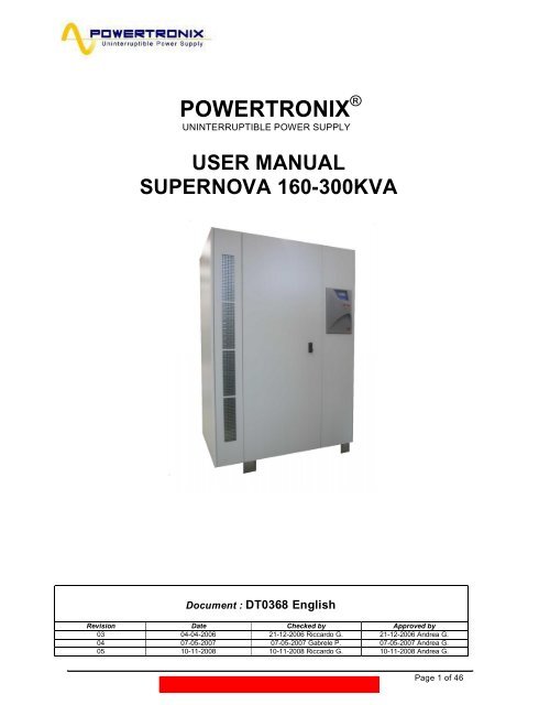
<strong>POWERTRONIX</strong> ® UNINTERRUPTIBLE POWER SUPPLYUSER MANUALSUPERNOVA 160-300KVADocument : DT0368 EnglishRevision Date Checked by Approved by03 04-04-2006 21-12-2006 Riccardo G. 21-12-2006 Andrea G.04 07-05-2007 07-05-2007 Gabrele P. 07-05-2007 Andrea G.05 10-11-2008 10-11-2008 Riccardo G. 10-11-2008 Andrea G.R&D – USER MANUAL DT0368-E05 Page 1 of 46
R&D – USER MANUAL DT0368-E05 Page 2 of 46
INDEX1 GENERAL INFORMATION ..................................................................................................................... 51.1 GENERAL DESCRIPTION OF THE UPS ................................................................................................. 51.1.1 Fields of use of the UPS .............................................................................................................. 51.1.2 Power and autonomy ................................................................................................................... 51.1.3 Safe and easy use ....................................................................................................................... 51.2 CONFIGURATIONS AND OPTIONAL EQUIPMENT ....................................................................... 61.2.1 Base configuration ....................................................................................................................... 61.2.2 Battery cabinet ............................................................................................................................. 61.2.3 Transformer cabinet ..................................................................................................................... 61.2.4 Circuits for remote communication .............................................................................................. 71.2.5 UPS MANAGEMENT Software.................................................................................................... 71.2.6 Remote panel............................................................................................................................... 81.2.7 Remote EPO pushbutton panel ................................................................................................... 81.3 OPERATING PRINCIPLE ....................................................................................................................... 91.3.1 UPS block diagram ...................................................................................................................... 91.3.2 Input stage, power module and output stage............................................................................... 91.3.3 Logic and auxiliary circuits ......................................................................................................... 101.3.4 Batteries ..................................................................................................................................... 101.3.5 Manual by-pass.......................................................................................................................... 101.3.6 Front panel ................................................................................................................................. 102 INSTALLATION INSTRUCTIONS.......................................................................................................... 112.1 GENERAL INFORMATION.................................................................................................................... 112.2 RECEPTION AND IDENTIFICATION....................................................................................................... 112.3 STORAGE ......................................................................................................................................... 112.4 POSITIONING THE UPS...................................................................................................................... 122.5 ROOMS SPECIFICATIONS................................................................................................................... 142.6 LAYOUT AND CONNECTION TO MAINS................................................................................................ 152.7 UPS AUXILIARY CONNECTIONS......................................................................................................... 182.7.1 Remote communication board ................................................................................................... 192.7.2 Synoptic panel ........................................................................................................................... 202.7.3 Ups management software ........................................................................................................ 212.7.4 Remote EPO button................................................................................................................... 212.8 EARTHING ........................................................................................................................................ 213 CONTROL PANEL ................................................................................................................................. 223.1 INTRODUCTION ................................................................................................................................. 223.2 MENU 1: STATUS OR ALARM DISPLAY ............................................................................................... 253.2.1 UPS IN FAULT CONDITIONS ................................................................................................... 263.3 MENU’ 2: MEASUREMENT DISPLAY .................................................................................................... 273.4 MENU’ 3: UPS CONTROLS ................................................................................................................. 273.5 MENU’ 4: GUIDED PROCEDURES ....................................................................................................... 283.6 MENU 5: PANEL CONFIGURATION ...................................................................................................... 283.7 MENU 6: EVENT LOG DISPLAY........................................................................................................... 283.8 MENU 7: SERVICE ........................................................................................................................ 294 INSTRUCTIONS FOR USING THE UPS ............................................................................................... 304.1 INTRODUCTION ................................................................................................................................. 304.2 POWER SWITCHES ...................................................................................................................... 304.3 GUIDED PROCEDURES....................................................................................................................... 324.4 INSTRUCTIONS FOR TURNING ON THE UPS ............................................................................ 324.5 INSTRUCTIONS FOR ENABLING THE MANUAL BY-PASS ....................................................................... 344.6 INSTRUCTION FOR RETURNING FROM MANUAL BY-PASS TO NORMAL OPERATION.............................. 354.7 INSTRUCTIONS FOR COMPLETELY SHUTTING OFF THE UPS................................................................ 36R&D – USER MANUAL DT0368-E05 Page 3 of 46
4.8 E.P.O. (EMERGENCY POWER OFF) EMERGENCY STOP ...................................................................... 364.9 INSTRUCTIONS FOR TURNING ON THE UPS IN POWER SAVE MODE .................................................... 374.10 INSTRUCTIONS FOR ENABLING THE MANUAL BY-PASS IN POWER SAVE MODE .................................... 384.11 INSTRUCTIONS FOR RETURNING FROM MANUAL BY-PASS TO NORMAL OPERATION IN POWER SAVEMODE 394.12 INSTRUCTIONS FOR COMPLETELY SHUTTING OFF THE UPS IN POWER SAVE MODE............................. 40MANAGING THE UPS BATTERY ....................................................................................................................... 414.13 BATTERY TEST PROGRAMMING ......................................................................................................... 415 UPS IN PARALLEL ................................................................................................................................ 425.1 SYSTEM SET-UP............................................................................................................................... 426 MACHINE FAULTS ................................................................................................................................ 436.1 GENERAL ALARMS ............................................................................................................................ 436.2 FIRE................................................................................................................................................. 456.3 FAULTS RELATED TO THE NATURE OF THE LOAD .............................................................................. 457 SCHEDULED MAINTENANCE .............................................................................................................. 467.1 ANNUAL MAINTENANCE (OR SIX MONTHLY IN THE CASE OF HIGHLY CRITICAL MISSION UPS) .................. 467.2 SCHEDULED COMPONENT REPLACEMENT .......................................................................................... 46R&D – USER MANUAL DT0368-E05 Page 4 of 46
1 GENERAL INFORMATION1.1 GENERAL DESCRIPTION OF THE UPSThe UPS in question is composed of a metallic frame inside which the electronic power part isdeveloped, accessible from the front painted doors.The external panelling of the machine can be completely removed; so that it is easy to accessfrom all sides for any purpose.The right front door contains the user interface panel, for controlling and running the UPS.Given the specific power of the UPS it is not equipped with internal batteries, these are locatedin one or two dedicated cabinets.The cooling system of the machine is composed of a hydraulic circuit (filled with water and anaddition of glycol) and forced air, suctioned from the base of the UPS and ejected by a systemof front ventilation grids in the exchanger section, located on the left of the front of the machine1.1.1 Fields of use of the UPSThe new UPS is designed to supply stabilised and filtered power to sophisticated electronicsystems (in particular to data processing systems) which need to be guaranteed a power sourcefree from voltage and frequency fluctuations, thus hospitals, police stations, motorway tunnels,radio stations, banks, technical and administrative offices and many other applications.1.1.2 Power and autonomyThanks to its modular design the UPS is available in versions with rated power from 160KVA to300KVA.Internal batteries are not used for all sizes of the UPS, thus it is necessary to use separatebattery cabinets to create the desired autonomy.1.1.3 Safe and easy useAll of the available controls are perfectly insulated and disconnected from hazardous voltages.Controls both on overloading and excessive temperatures guarantee the immediate and mostopportune intervention in the event that one of these conditions occurs during operation.The operator can view the status of the UPS on the front panel and perform shutdown orswitching operations easily. See chapter 3 page 19.It is possible to connect one of more external E.P.O. emergency buttons (not supplied) used tocontrol the complete deactivation of the UPS in the event of a fire. Chap.2.7.4Monitoring of the UPS can be managed remotely, with maximum simplicity through a personalcomputer and a specific communication program (optional) or via a remote panel (also optional)which is indispensable if the system will be installed in unmonitored areas. See chapters 1.2.5 -1.2.6R&D – USER MANUAL DT0368-E05 Page 5 of 46
1.2 CONFIGURATIONS AND OPTIONAL EQUIPMENT1.2.1 Base configurationThe base configuration entails the implementation ofthe UPS in a single cabinet. It maintains the samemechanical dimensions in all the availableconfigurations and sizes:-6 pulse 160-300kVA-12 pulse 160-300kVA-12 pulse + low THD 160-300KVA1.2.2 Battery cabinetIf requested the UPS can be supplied complete with batteries for the requestedautonomy.The batteries will be housed in an appropriately sized cabinet, complete withdisconnection and protection parts.For batteries not housed in a standard cabinet, it is necessary to create a disconnectionand protection panel for them.1.2.3 Transformer cabinetAn optional cabinet is available with galvanic isolation transformer (output-mainsreservenetwork) for specific uses.The standard transformer is three phase/three phase with 1:1 ratio but it can besupplied with a different transformation ratio upon request.R&D – USER MANUAL DT0368-E05 Page 6 of 46
1.2.4 Circuits for remote communicationM1Remote communicationboard ( the codeCS0098), givespossibility of monitoringand communicating withUPS.Monitoring can beimplemented with thePC and dedicatedsoftware or through aremote panel. There arealso free contacts available on the terminal board M1 ( more info at page 19)CN1CN31.2.5 UPS MANAGEMENT SoftwareThe Generex “UPS MANAGEMENT”communication software: used forcommunication between the UPS and a PCor network of PC based on Windows, Win-NT, Novell, OS2, Dec, Linux operatingsystem.The software is used to control theoperating condition of one or more UPSused to supply a personal computer LAN.(for more information see the chap.AUXILIARY CONNECTIONS OF THE UPSon page 17).R&D – USER MANUAL DT0368-E05 Page 7 of 46
1.2.6 Remote panelThe remote panel is used for remote viewing of the UPS operation, it repeats the statusof the main blocks with switching on of LEDs and activation of an acoustic alarm.(for more information see the chap. AUXILIARY CONNECTIONS OF THE UPS on page17).1.2.7 Remote EPO pushbutton panelThe remote EPO pushbutton panel is a safety system that gives you the possibility ofcompletely disabling the machine in the event of an emergency.(for more information see the chap. AUXILIARY CONNECTIONS OF THE UPS on page17).R&D – USER MANUAL DT0368-E05 Page 8 of 46
1.3 OPERATING PRINCIPLEThe UPS described here is an on-line dual conversion type UPS with automatic by-passin compliance with European standard EN62040-1-2. This UPS performs a dualconversion of the incoming voltage continuously and without interruption.The absence of direct mains-load connection does not allow the passage of anydisturbance and the dual conversion guarantees an output of always regulated energy,both in voltage and frequency, ideal for the operation of professional uses.When the input voltage goes out of the allowed tolerances or more simply is notpresent, the load is supplied by taking energy from the batteries.The system is supplied with an automatic by-pass; in the event of a fault or overload ofthe UPS, the by-pass connects the uses directly to the mains via a reserve line, thusmaking it possible to restore normal operating conditions without supply interruptions tothe load. See fig. 1.3.11.3.1 UPS block diagramI3MANUAL BY-PASSMANUAL BY-PASS3PH + N + PERESERVE LINEI2I1RESERVE LINERECTIFIER - STEP UP CONVERTER INVERTER STATIC SWITCHI4MANUAL BY-PASSMAINS INPUT OUTPUT-LOAD 3PH + N + PEBATTERY CAHRGER BATTERY CABINETFig. 1.3.11.3.2 Input stage, power module and output stageFrom the input bars the mains are connected via the MAINS INPUT l1 switch to thepower module.The rectifier-step-up converter controlled by the control logic, applies the AC/DCconversion to the mains (normal operating condition) or the DC/DC conversion of thebattery energy when the mains power is absent or not within the allowed tolerance.The DC voltage then powers the inverter which reconstructs AC voltage adjusting thecurrent taken based on the load needs.The last module is the automatic by-pass. It transfers the filtered and regeneratedenergy from the Inverter to the load, in normal operating conditions, if there is a fault oroverload, the UPS output is switched to the reserve line; in this situation it is the mainswhich maintain the power to the uses. When the causes that provoked switching to thereserve line cease, the by-pass automatically returns to the supply from the inverter.The filtered, regenerated and stabilised mains is sent to the load via the UPSOUTPUTl4 switch. See diagram 1.3.1R&D – USER MANUAL DT0368-E05 Page 9 of 46
1.3.3 Logic and auxiliary circuitsThe control logic is housed on a specific board (CS0090) and represents the“intelligence” of the UPS.It manages operation of the step-up converter, inverter and by-pass based on feedbackcomparison of signals taken from the power module. The control logic also manages theother three boards, i.e. the battery charger, auxiliary power supply and signal interface.The battery charger handles recharging of the outside batteries connected to the UPS.The signal interface takes the signals from the control logic and converts them into theprotocol required for the front panel of the UPS and the relay boards. Going backwards,the criteria from the front panel (automatic by-pass forcing) and/or Relay board (EPO)are sent from the signal interface to the control logic which interprets them and switcheson the reserve line and/or immediately shuts off the UPS.The signal interface may also pilot another optional board (second relay board) inaddition to the standard relay board.The auxiliary power supply supplies all the boards and electronic components in theUPS.1.3.4 BatteriesThe battery supplies energy to the system when the input mains is not suitable or notpresent, in all other cases it is constantly recharged by the battery charger module sothat it is always ready for use when required.1.3.5 Manual by-passThe use of the manual by-pass is for cases when it is necessary to disable the UPSkeeping the load supplied from the mains (e.g.: UPS stopped, fault, etc.). It is a circuitthat can be activated via the MANUAL BY-PASS l4 switch, located on the front part ofthe UPS, see chap. 4. In normal operating conditions of the UPS this circuit breaker is inhome position with a mechanical safety locked inserted (lock with key).1.3.6 Front panelThe UPS is managed via the front panel, from which it is possible to run the controls,and display and reset the alarm circuits.The panel is equipped with an LCD used to display the operating status of the UPS, thecharge and all types of measurement (see chap. 3)R&D – USER MANUAL DT0368-E05 Page 10 of 46
2 INSTALLATION INSTRUCTIONS2.1 GENERAL INFORMATIONThis chapter describes the system installation procedures and lists the followingsubjects:2.2 Reception and identification2.3 Storage2.4 Positioning the UPS2.5 Room specifications2.6 Arrangement and connection to mains2.7 UPS auxiliary connections2.8 Earthing2.2 RECEPTION AND IDENTIFICATIONAfter removing the packing, visually inspect (inside and outside) the UPS and batterypanel (if included) to check for any damage that occurred during shipping. If there is anydamage inform the shipper or retailer immediately.Check the supplied material against the packing slip.The machine has an adhesive identification plate indicating the type, power and serialnumber; it is located inside the right door.Fig. 2.22.3 STORAGEIf the system is not going to be installed immediately it must be stores in an environmentwith adequate protection against excessive humidity and sources of extreme heat (from+5 to +40°C, humidity less than 95% without condensation).If the battery panel is supplied, also make sure that no more than 6 monthspasses between one battery recharge and the next. Once this period of time haselapsed, temporarily hook the UPS up to the mains and run it for the time needed torecharge the batteries.R&D – USER MANUAL DT0368-E05 Page 11 of 46
2.4 POSITIONING THE UPSAll of the sizes and configurations of this UPS series have been developed with thesame structure, their mechanical specifications are listed in tables 2.4 a-b-c.POWER(KVA)DIMENSIONSLxDxH (mm)Withoutexchanger6 PULSE VERSIONDIMENSIONS WEIGHT (Kg)LxDxH (mm) WithoutWith exchanger exchangerWEIGHT (Kg)With exchanger160 540 570200 1040 x 800 x 1240 x 800 x 570 600250 18001800600 630300600 630Tab. 2.4aPOWER(KVA)DIMENSIONSLxDxH (mm)Withoutexchanger12 PULSE VERSIONDIMENSIONS WEIGHT (Kg)LxDxH (mm) WithoutWith exchanger exchangerWEIGHT (Kg)With exchanger160 690 720200 1040 x 800 x 1240 x 800 x 690 720250 18001800840 870300840 870Tab. 2.4bPOWER(KVA)DIMENSIONSLxDxH (mm)Withoutexchanger12 PULSE VERSION + 5% THDDIMENSIONSLxDxH (mm)With exchangerWEIGHT (Kg)WithoutexchangerWEIGHT (Kg)With exchanger160 750 780200 1040 x 800 x 1240 x 800 x 750 780250 18001800960 990300960 990Tab. 2.4cThe weights and dimensions are differentiated because the liquid – air exchanger of themachine may be built-in to the UPS cabinet or installed in a separate, distant area from it.For handling you need to remember that the machine, unless special arrangements aremade, is shipped and thus handled with the exchanger attached, thus you need to referto the bigger dimensions and higher weight of the version used.Once the cabinet is removed from the packing, it can be moved on a pallet with fork liftfrom the front or the side to the installation site.Remember that all the connections enter from the bottom of the UPS under thesupport surface on the right (fog. 2.4)R&D – USER MANUAL DT0368-E05 Page 12 of 46
Fig. 2.4 shows the bars for housing the cablesMAINS INPUTLOADOUTPUTRESERVENETWORKINPUTPOS - NEGBATTERYEARTH BARFig. 2.4CABLEENTRANCELooking at the UPS from the front, the entrance of the cables is to the lower right, theycan be accessed by removing the painted side piece.All of the cables need to be inserted from the bottom in the specific window for insertingthem as shown in figure 2.4R&D – USER MANUAL DT0368-E05 Page 13 of 46
2.5 ROOMS SPECIFICATIONSThe room where the UPS is installed must be clean and must be pollution class 2(CEI); it must also be able to dissipate the heat produced by the machine, as shown intable 2.5a.Tab. 2.5aPowersDiss. P (KWwithexchanger160 8,2 3,5200 9,9 4,1250 12,8 5,3300 15,5 6,5Rated P(KVA)Diss. P(KW)withoutexchangerIf the installation also includes the battery panel, the room must be able to ensure anexchange of air equal or greater than what is shown in table 2.5b.Tab. 2.5bAir exchange only for battery hydrogenAir exchangefor 15m auto.(m 3 /h)Air exchangefor 30m auto.(m 3 /h)Air exchangefor 1h auto.(m 3 /h)10 19 3213 26 4216 32 5219 39 62Remember that the average life of the batteries is closely tied to the operatingtemperature; a temperature of around 20°C is normally recommended.(When the temperature rises above 20°, for each 10°higher the battery life drops by 50%)R&D – USER MANUAL DT0368-E05 Page 14 of 46
2.6 LAYOUT AND CONNECTION TO MAINSFor connection to the mains a layout solutions like the one shown in diagram 2.6° isrecommended. The circuit breakers B-C-D are a magnetothermic type withoutdifferential protection, or if this is required, with a triggering current greater than 0.5AStandard reserveLoadStandard mainsDBY-PASSDISTRIBUTION PANELBI3BY-PASSI2RESERVERESERVE LINEI4OUTCI1=INPUTUPSStandard mainsBATTERY1Standard reserveDiagram 2.6aIBT1BATTERY CABINETR&D – USER MANUAL DT0368-E05 Page 15 of 46
The control parts and all the power connections of the UPS in question need to be ableto permanently support the current shown in tab. 2.6UPS power(KVA)Mains input(A)Reserve input(A)Use outputs (A)Batterydischargecurrent (A)160 242 242 242 350200 302 302 302 438250 378 378 378 547300 454 454 454 600Table 2.6WARNING !!IN ADDITION TO THE CIRCUIT BREAKER AND PROTECTION IT IS ADVISABLE TOSET UP AN APPROPRIATE CHANGE-OVER CONTACT ON THE NETWORK INPUTSIDE OUTSIDE THE UPS TO PROTECT AGAINST VOLTAGE RETURNS ASINDICATED IN TABLE 2.6 AND THE FOLLOWING TABLE:If necessary a system against voltage return needs to be created in the UPS distributionpanel as shown in diagram 2.6bA: general mains circuit breaker / switchC: automatic switch or at least a fuse for the mainsB: automatic switch or at least a fuse for the reserve networkK3: protection contactor against return voltageK1-K2: additional relays on the change-over contact coil supplyDISTRIBUTION PANELUPSL1L2L3NEUTABK3L1-RESERVEL2-RESERVEL3-RESERVENEUTRALK1K2CL1-MAINSL2-MAINSL3-MAINSNEUTRALDiagram 2.6bR&D – USER MANUAL DT0368-E05 Page 16 of 46
WARNING!!BEFORE CONNECTING THE UPS MAKE SURE THE LINES THAT CONNECT THEUPS MAINS AND RESERVE INPUTS TO THE DISTRIBUTION PANEL ARE OPEN ANDDISCONNECTED MAKE SURE THAT THE BATTERY PANEL SWITCH IS OPEN.PUT WARNING SIGNS ON THE DISTRIBUTION PANEL AND BATTERY PANEL TOPREVENT ACCIDENTAL ACTIONS.MAINS INPUTLOAD UPSOUTPUTCABLE HOUSINGBARRESERVENETWORKINPUTFigure 2.6: Detail of open UPS panel to show cable entranceBefore connecting the UPS it is necessary to:- make sure that the mains voltage and frequency match those indicated on theadhesive plate located on the inside of the right door of the UPS (input voltage,operating frequency, etc.);- make sure that the earthing of the system fully complies with the requirements ofIEC standards or local laws.Then install four pole magnetothermal switches (see Fig.2.6b) upstream anddownstream from the UPS with the following specifications:R&D – USER MANUAL DT0368-E05 Page 17 of 46
- capacity equal or greater than what is indicated on the label inside the right door(KVA);- specifications in compliance with IEC standards or local laws for Curve C”magnetothermals.- The connections needs to be made using flexible cables with a cross-section(minimum) as indicated in the following table:P (KVA) Ø A.C. (mm 2 ) I A.C. (A) Ø D.C. (mm 2 ) I D.C. (A)160 (KVA) 95 242 2x50 350200 (KVA) 2x50 302 2x70 438250 (KVA) 2x70 378 2x95 547300 (KVA) 2x95 454 2x120 6002.7 UPS AUXILIARY CONNECTIONSThe communication boards are housed above the UPS disconnection parts. Thestandard equipment is composed of a remote communication board (CS0098) and setupfor the SNMP board.It is possible to install another optional remote communication board (CS0098) inaddition to the standard one upon request (for. 2.7a).Access for the connections to these devices is located on the rear part of the UPS(fig.2.7b)SNMPOptionalrelay boardStandard relay boardR&D – USER MANUAL DT0368-E05 Page 18 of 46
2.7.1 Remote communication boardRemote communication board is used to allow connection between the UPS andexternal device.The board has a series of voltage free contacts terminals (M1) which can be connectedto a dedicated synoptic panel (chap. 2.7.2), acoustic or visual warning device or remotesignalling systems.One or more remote EPO buttons (chap. 2.7.4) can be connected via the other twocontacts (CN1). Lastly, it’s possible to connect the system to a PC via a DB9 connector(CN3) and use the specific software (chap. 2.7.3)Figura 2.7aFig. 2.7.1aFree contacts on CS0098Battery LowMains not presentManual By-PassFig. 2.7.1bInverter RunR&D – USER MANUAL DT0368-E05 Page 19 of 46
2.7.2 Synoptic panelThis is connected to the UPS via the terminal board M1 located on the remotecommunication board (CS0098)(connection diagram fig. 2.7.2a). This device is used forremote monitoring of the main UPS blocks, the status of the main blocks is representedthrough LEDs, and there is also an acoustic alarm, which can be shut off with key 5.LED description1) Green ON UPS LEDIf on the UPS is operating correctlyIf off it indicates that one or more inverter section alarms are present(acoustic alarm enabled)2) Yellow ON BATTERY LEDIf on the UPS is operating by battery(acoustic alarm enabled)3) Red LOW BATTERY LEDIf on it indicated imminent end of battery discharge(acoustic alarm enabled)4) Yellow ON BYPASS LEDIf on it indicates load supplied from reserve(acoustic alarm enabled)5) ALARM SILENCE keyUsed to shut off the acoustic alarmFig. 2.7.2b6) Green LEDIf on it indicates correct power supply to synoptic panelDB9594837261Male ConnectorM11211102 K1193 84 75 6512V-12A4321UPS RemotePanelM11 Battery LOW2 Ups ON3 On By-Pass4 Mains Status5 Common678CS0098 Relay BoardEXT SUPPLYCS0098RelayBoard112942-5-8-11UPSREMOTEPANEL12345NOTE:ON CS0098 COMMON TAGBLOCKS (2-5-8-11)MUST BE CONNECTED TOGETHERFig. 2.7.2aR&D – USER MANUAL DT0368-E05 Page 20 of 46
2.7.3 Ups management softwareThis software is used to monitor the conditions of the UPS via a PC connected to thesystem by the supplied cable.For more information on the installation and use of the software see the manual thatcame with it.2.7.4 Remote EPO buttonParticular attention must be paid to the external connection of buttons or actuators for theEPO function (emergency stop). This connection is composed of a series or normallyclosedswitches which open the series if commanded, generating the stop of the UPS withthe consequent and irreversible interruption of voltage to the load. The series of externalEPO buttons must be connected to the CN1 terminal board of the relay board CS0098(Fig.2.7.4). If there are no external EPO contacts to the system jumper JP1 must beenabled. (circle in fig.2.7.1a)The default configuration (without the ext. E.P.O connected) has the connector CN1shortened with a wire connection, it must be removed (as well as the jumper JP1), whenone or more E.P.O. ext. will be connected to the board as described above.Fig. 2.7.42.8 EARTHINGThe earth input cable must be connected to the earth commutator of the UPS and mustbe always the first cable to be connected. It is advisable to insert an appropriateantioxidant between the earth bar and lug to keep the correct contact over time.All of the cabinets and accessories must be earthed in accordance with localregulations.WARNING !!INADEQUATE EARTHING MAY CAUSE A RISK OF ELECTRIC SHOCKS TOPERSONNEL OR FIRE.R&D – USER MANUAL DT0368-E05 Page 21 of 46
3 CONTROL PANEL3.1 INTRODUCTIONThe control panel is located on the front part of the UPS, it is used to easily check thegeneral status of the UPS, batteries and related alarms.The control panel is composed of an LCD display which indicates the operating status,measurements and alarms of the UPS and an EPO button located at the lower right ofthe panel.The display panel shows text messages and operating parameters on an LCD screenwith 4 lines and 20 characters per line.The screens are organised in 7 multi-level menus, which can be selected using themembrane buttons under the LCD display.Figure 3-1aTwo LEDs are present on the left side of the display, a green one called “NORMAL” anda red one called “ALARM”.The actions of the LEDs are summarised in table 3.1a.R&D – USER MANUAL DT0368-E05 Page 22 of 46
STATUS UPS OK Alarm present Alarm stoppedGREEN LED on off onRED LED off on flashingTabella 3.1aIn the event of parallel systems during normal operation the green LED will flash on themaster UPS to identify it.LCD CONTROL PANELFIGURE 3-1B COMPOSITION OF LCD PANELESC PUSHBUTTONShut off the buzzerMENU’PUSHBUTTONTo return to theprevious level menuBACK PUSHBUTTON NEXT PUSHBUTTONIt is possible to scroll between the 7 mainsmenu or submenu. By pressing it at the sametime you select ENTERDuring normal operation of the UPS the control panel uses a series of messages todisplay the operating status of the single component blocks of the system, thus theoperator is informed in real time (buzzer) of any faults presented by the system.Table 3-1b summarises the list of available menus in order.MENU N° NOTESStatus or alarm display 1 If keys are not used on another menu after 3minutes, it returns always openMeasurement display 2 Used to display the values of all themeasurementsUPS controls 3 Inverter on / off, static switch, batt. testGuided procedures 4 Displayed when the system is turned onPanel configuration 5 Setting for date / time / batt. test / languageEvent log display 6 Displays the log of events and related alarmsService 7 Reserved for technical assistance serviceTable 3-1bR&D – USER MANUAL DT0368-E05 Page 23 of 46
It is possible to scroll between the 7 menus listed in table 3-1b using the NEXT(>) orBACK() and BACK()and by confirming the selection go to the next level..To return to the previous level press the MENU keyEach alarm indication on the display is followed by a buzzer which can be shut off bypressing ESC (see figure 3-1b)When the UPS is turned on the display is automatically positioned in menu no. 4“GUIDED PROCEDURES” which proposes turning on the system.At this point the operator can decide whether to follow the proposed procedure byfollowing the instructions shown on the display until the system is completely activated orperform operations different than turning on the system via the MENU key.If the operator does not perform any action, the “STATUS AND ALARM DISPLAY 1”menu is automatically displayed after 3 minutes.R&D – USER MANUAL DT0368-E05 Page 24 of 46
3.2 MENU 1: STATUS OR ALARM DISPLAYThis menu is characterised by the first line of the message which can be UPSOPERATING (if the UPS is operating normally) or UPS ALARM (if the UPS has analarm condition). The meanings of the displayed messages are given below:UPS IN NORMAL OPERATING CONDITIONSMESSAGEMAINS SUITABLE / NOT SUITABLERESERVE SUITABLE / NOT SUITABLEBATTERY VOLTAGE SUITABLEINVERTER ONINVERTER – RESERVESYNCHRONISED / NOTSYNCHRONISEDLOAD ON INVERTERLOAD ON RESERVEMASTER UPSSLAVE UPSMEANINGThe input mains line is on and the voltageis / is not in the specified rangeThe input by-pass supply line is on and thevoltage is / is not in the specified toleranceThe battery voltage is within the specifiedlimitsThe inverter is on and operating normallyIndicates the normal synchronisationstatus betweenthe inverter and by-pass lineThe load is supplied by the inverterThe load is supplied by the by-pass line.This may be a temporary condition whichlasts 20 seconds when there is a shortoverloadControls the UPS in parallelControlled by another UPS in parallelTable 3-R&D – USER MANUAL DT0368-E05 Page 25 of 46
3.2.1 UPS in fault conditionsIf the UPS has a fault, the status screen will be replaced with the alarm one.A message will appear on the type of fault that occurred. A buzzer will be activated thatcan be shut off by pressing the ESC key. By ENTER (< >) a list of indications will bedisplayed to guide the operator to understand the meaning of the alarm. The keys can be used to scroll between the various indications. When the alarmcondition is removed, the LCD returns to the default screenUPS ALARMALARM CAUSE< BACK or NEXT>The possible alarms and associated help messages are listed below.ALARM MESSAGEINVERTER OFFINVERTER OVERLOADSTATIC SWITCH BLOCKEDBATTERY FAULTBATTERY TEST FAILEDBATTERY PREALARMSTATIC SWITCH FAULTMANUAL BY-PASSENABLEDMAINS NOT SUITABLERESERVE NOT SUITABLEEMERGENCY STOPBATTERY CHARGERFAULTNO PARALLEL DATAEXCHANGEMEANINGThe load is no longer supplied by the inverterand thus subject to any mains failuresThe inverter is off due to an overload and theuses are supplied by the reserve networkAfter 3 unsuccessful automatic switchingattempts from the reserve to inverter, the UPSblocks the static switch on the reserve networkDisplayed whenever the periodic test on thebattery fails for any reasonAt a battery voltage of around 440V the UPSwarns the user of a low battery valueAt 400V discharging ends and the UPS goes offOne or more output phases missingDisplayed when the manual BY-PASS circuitbreaker is closedThe mains is not suitable for the UPSspecifications, it may be higher or lower than thetolerances allowed by the system, or simply notpresentThe reserve is not suitable for the UPSspecifications, it may be higher or lower than thetolerances allowed by the system, not presentor with incorrect cyclic directionDisplayed whenever the E.P.O. button ispressed, for whatever reasonDisplayed for a fault in the battery charger or if itis not connectedThis alarm occurs when there is not dataexchange between various UPS in parallel, forwhatever reason It may be due to a missing orincorrect connection of one or more parallelfibresR&D – USER MANUAL DT0368-E05 Page 26 of 46
3.3 MENU’ 2: MEASUREMENT DISPLAYTo access this screen press ENTER on 2.Measurement Display on the main menuThe operator can now check the value of the following electrical measurements byscrolling with the arrows < or >:V in phase - neutral = reserve network Y-voltageV in phase/phase = reserve network voltage between linesInput current = UPS input three phase currentsV out phase/neutral = UPS output Y-voltageOutput current = output current at loadBattery V,I = battery voltage and currentKVA,KW power distributed = power distributed by UPSPower factor = power factor distributed by UPSFrequency = UPS output frequencyIf no operation is performed, the “STATUS AND ALARM DISPLAY 1” menu is displayedafter 3 minutes.3.4 MENU’ 3: UPS CONTROLSFrom this menu it is possible to give operating control to the UPS.MESSAGE3.1 INVERTER ON3.2 INVERTER OFF3.3 SWITCH LOADTO INVERTER3.4 SWITCH LOADTO RESERVE3.5 RUN BATTERYTESTMEANINGWith this message by pressing ENTER the use can turn theinverter permanently on or offIt is necessary to turn the inverter on when starting and after astop for a permanent overload.With this message by pressing ENTER the load is moved fromthe reserve line to the inverter.With this message by pressing ENTER the load is movedfrom the inverter to the reserve line.With this message by pressing ENTER an automatic test will bestarted instantaneously on the battery, which lasts for around 30seconds.If no operation is performed, the “STATUS AND ALARM DISPLAY 1” menu is displayedafter 3 minutes.R&D – USER MANUAL DT0368-E05 Page 27 of 46
3.5 MENU’ 4: GUIDED PROCEDURESMESSAGEMEANING4.1 UPS START-UP Guides the operator for starting the machine step by step4.2 SHUTDOWN Guides the operator for shutting down the machine step by step4.3 MANUAL BYPASSACTIVATIONGuides the operator for shutting down the UPS maintainingpower to the uses from the reserve network via manual bypass4.4 MANUAL BYPASSDEACTIVATIONGuides the operator for reactivating the UPS maintaining powerto the uses starting from manual bypassIf no operation is performed, the “STATUS AND ALARM DISPLAY 1” menu is displayedafter 3 minutes.3.6 MENU 5: PANEL CONFIGURATIONMESSAGE5.1 DATESETTING5.2 TIMESETTING5.3 BATTERY TESTSETTING5.4 LANGUAGESETTINGMEANINGUsed to set the current date, using the arrows to increase /decrease the numbersUsed to set the current time, using the arrows to increase /decrease the numbersUsed to set the periodic battery test, selecting the day of theweek, the number of weeks between one test and the next andthe time of day to start the testUsed to select the display language between Italian, Spanish,English, French or GermanIf no operation is performed, the “STATUS AND ALARM DISPLAY 1” menu is displayedafter 3 minutes.3.7 MENU 6: EVENT LOG DISPLAYIn this menu the user can scroll through the last 1024 events / alarms in chronologicalorder.The event log display can be opened by selecting 6. EVENT LOG in the main menu andthen DISPLAY LOG. The screen will show the date and time of the last event thatoccurred.It is possible to scroll the list using the buttons In all positions on the event list, by pressing MENU the display returns to the MAINMENU.To delete all the events select DELETE EVENTS from the submenu and thenpress .If no operation is performed, the “STATUS AND ALARM DISPLAY 1” menu is displayedafter 3 minutes.R&D – USER MANUAL DT0368-E05 Page 28 of 46
3.8 MENU 7: SERVICEThe control board can be connected to a laptop via optical fibres, in order for servicingpersonnel to perform troubleshooting or change the calibrations of the UPS.To perform this procedure or check the signalling program software revision, you needto enter the menu 7. SERVICE PROCEDURES, however this menu is protected bypassword and cannot be accessed by unauthorised personnel.If no operation is performed, the “STATUS AND ALARM DISPLAY 1” menu is displayedafter 3 minutes.R&D – USER MANUAL DT0368-E05 Page 29 of 46
4 INSTRUCTIONS FOR USING THE UPS4.1 INTRODUCTIONThis chapter describes the control parts of the UPS which can be used by the operatorto correctly use the system.The UPS may be in one of the following operating conditions: Normal operation - The load is supplied by the UPS.The UPS is in normal operation and uses mains supply to supply energy to theuses and charge the batteries.This mode guarantees complete uninterrupted power to the uses.Operation with internal automatic by-pass – The load is supplied by the mainsIn the event of an inverter fault and/or overload, the power to the uses isguaranteed by the reserve network.This mode does not guarantee complete uninterrupted power to the uses. Operation with maintenance manual by-pass enabled – The UPS is disabled.The load is connected directly to the mains through the maintenance oremergency manual by-pass line.This mode does not guarantee complete uninterrupted power to the uses. Battery operation - The load is supplied by the UPS.The UPS is in normal operation and uses battery supply to supply energy to theuses because the mains is not present.This mode guarantees complete uninterrupted power to the uses.4.2 POWER SWITCHESThe UPS control parts are located behind the right front door and are installed verticallyin the order described below (see fig. 4.3):MAINS INPUT SWITCH (I1): connects the UPS to the mains input supply.USES OUTPUT SWITCH (I4): connects the UPS to the usesRESERVE INPUT SWITCH (I2): connects the UPS to the reserve network supply.MANUAL BY-PASS SWITCH (I3): used to disable the UPS keeping the uses suppliedby the mainsIt is protected by a mechanical lock to prevent accidental operations.All of the UPS circuit breakers have been described with the exception of the batterycircuit breaker, which is located on the battery panel, or at least outside the UPScabinetTo completely isolate the machine from hazardous voltages it is necessary toalso open the battery switch, not present on the UPS.Also remember that the presence of potentially loaded capacitors inside theconverter means you must wait for at least 10 minutes before accessing theinternal parts of the machine.R&D – USER MANUAL DT0368-E05 Page 30 of 46
WARNING !A HORIZONTAL LEVER IS THE SAME AS AN OPEN SWITCH, A VERTICAL LEVER(TURNED CLOCKWISE) IS THE SAME AS A CLOSED SWITCHIn fig. 4.3 all the switches are shown in the OFF position:I1 MAINSINPUTI4 UPSOUTPUTI2 RESERVEINPUTFig. 4.3I3 MANUALBY-PASSWARNINGAll of the operations described in the following paragraphs must be performedby authorised electricians or trained personnel.R&D – USER MANUAL DT0368-E05 Page 31 of 46
4.3 GUIDED PROCEDURESUsing the selection in this menu it is possible to perform the following operations:- Turn on UPS;- Turn off UPS;- Enable manual by-pass- Return from manual By-Pass to normal UPS operation.Based on the selection made, the LCD will display all the operations that need to beperformed by the operator to correctly activate the selected option.The operator will be guided by a series of messages indicating the actions to perform onthe circuit breakers on the machine and the controls to make through the display.At the end of each one, if everything has been performed correctly, a confirm correctperformance message will appear.It is possible to perform the operations listed above without using the guidedprocedures, in this case exit from the menu “4. GUIDED PROCEDURES” and follow theinstructions listed in the paragraphs below.4.4 INSTRUCTIONS FOR TURNING ON THE UPSThis procedure is used to bring the UPS to normal operating conditions started from acompletely unpowered system.Before starting make sure that the system and all the electrical connections have bychecked by authorised personnel and that the external power switches are closedMake sure the lever of the MANUAL BY-PASS I3 switchis in the OFF position and mechanically locked(safety lock).MAKE SURE THE PHASE CYCLIC DIRECTION IS CORRECTFOR THE MAINS AND RESERVE NETWORK INPUTSee fig. 4.3 for the switches.If all of the points above have been checked, you can start the system as follows:1. Close the RESERVE NETWORK l2 circuit breaker.The LCD and all the UPS logics will begin operation (to disable the guided procedureproposed by the UPS default menu and access normal operating mode, press theMENU key)If the supply is correct on the reserve line the exchanger fans will go on.2. Close the UPS OUTPUT l4 switchThe loads connected to the UPS output will be supplied.R&D – USER MANUAL DT0368-E05 Page 32 of 46
3. Close the MAINS INPUT l1 switchWait for 10 seconds. A gradual start-up sequence of the main rectifier will be starter, sothat preloading of the internal capacity of the machine is carried out without causingmains side overcurrents.The INVERTER OFF message will appear on the LCD4. Activate the inverterUsing menu 3. CONTROL MODE select Inverter ON and press ENTER5. Check inverter network switchingWait 30 seconds, after which the static switch will automatically switch the load fromreserve line to inverter.Check the correct operating status, indicated if the green LED is on on the controlpanel.6. Battery connectionClose the battery panel switch thus connecting it to the UPS only after checking thecorrect polarity of the battery connection.At this point the machine is in normal operating mode, and is able to guaranteeuninterrupted power supply to the uses.It is advisable to simulate a power failure and ending of the failure to check the correctoperation of the entire UPS / Battery system.To perform this operation open and reclose the mains switch upstream from the UPS.WARNING:The start sequence described above must always be followed, in particular,remember THE SYSTEM CANNOT BE STARTED FROM THE BATTERY.R&D – USER MANUAL DT0368-E05 Page 33 of 46
4.5 INSTRUCTIONS FOR ENABLING THE MANUAL BY-PASSIf for maintenance purposes or other reasons you want to transfer the power supplies ofcritical uses directly to the mains, disabling the UPS in order to run tests on it or serviceit, proceed as follows:1. Select menu 3. CONTROL MODESelect the item “transfer load to reserve network” and press ENTERThe uses will now be supplied directly from the reserve network2. Turn off the inverterUsing menu 3. CONTROL MODE select Inverter OFF and press ENTERThis turns off the inverter and uninterrupted supply to the uses is no longer guaranteed3. Close MANUAL BY-PASS (I3):Remove the lock or any other mechanical safety lock from the switch and close it4. Open the MAINS i1 circuit breaker5. Open the RESERVE NETWORK l2 circuit breakerThe uses are directly supplied by the mains through the manual By-Pass6. Open OUTPUT l3 circuit breaker7. Disconnect the batteryAt this point the uses are directly supplied by the reserve network and the UPS doesnot have any hazardous voltage inside it with the exception of the compartmentwhere the input / output cables are housed, which is closed by a panel and theinverter DC and AC capacitors for a few minutes , however, to access then ametallic panel covering needs to be removed.R&D – USER MANUAL DT0368-E05 Page 34 of 46
4.6 INSTRUCTION FOR RETURNING FROM MANUAL BY-PASS TO NORMALOPERATIONTo return to normal operating conditions starting from the load on manual bypass,proceed as follows:1. Close the RESERVE INPUT l2 circuit breaker.At this point, if the supply on the reserve network is present and suitable the LCDdisplay goes on and all of the machine control start operation.The display automatically goes on the in GUIDED PROCEDURES mode, press theMENU key to exit.2. Close OUTPUT l4 circuit breaker3. Open MANUAL BY-PASS l3 circuit breakerAt this point the uses will be supplied by the reserve networkPut the mechanical lock back on the manual by-pass circuit breaker l34. Close the MAINS INPUT l1 switchWait for 10 seconds. A gradual start-up sequence of the main rectifier will be starter, sothat preloading of the internal capacity of the machine is carried out without causingmains side overcurrents.The INVERTER OFF message will appear on the LCD5. Start the inverterUsing menu 3. CONTROL MODE select Inverter ON and press ENTER6. Check inverter network switchingWait 30 seconds, after which the static switch will automatically switch the load fromreserve line to inverter.Check the correct operating status, indicated if the green LED is on on the controlpanel.7. Battery connectionClose the battery panel switch thus connecting it to the UPS only after checking thecorrect polarity of the battery connection.WARNING !The battery and its circuit breaker MUST always be connected to the UPSonly at the end of the start-up procedure, otherwise the system may notworkR&D – USER MANUAL DT0368-E05 Page 35 of 46
4.7 INSTRUCTIONS FOR COMPLETELY SHUTTING OFF THE UPSIf for maintenance or other reasons you want to completely shut off the system andleave the uses unpowered, proceed as follows:1. Select menu 3. CONTROL MODESelect the item “transfer load to reserve network” and press ENTERThe uses will now be supplied directly from the reserve network2. Turn off the inverterUsing menu 3. CONTROL MODE select Inverter OFF and press ENTERThis turns off the inverter and uninterrupted supply to the uses is no longer guaranteed3. Open LOAD l3 circuit breakerPower supply to the uses will no longer be supplied4. Open the RESERVE INPUT l2 circuit breaker.5. Open the MAINS l2 circuit breaker.6. Disconnect the BatteryAt this point the UPS does not have any hazardous voltage inside it with theexception of the compartment where the input / output cables are housed, which isclosed by a panel and the inverter DC and AC capacitors for a few minutes,however, to access then a metallic panel covering needs to be removed.4.8 E.P.O. (EMERGENCY POWER OFF) EMERGENCY STOPThe purpose of the emergency stop is to completely shut off the UPS if necessary withthe consequent and immediate opening of the static switch on the mains and invertersides. This removes the power supply and uninterrupted power supply to the uses.Obviously, hazardous voltages remain inside the UPS panel.R&D – USER MANUAL DT0368-E05 Page 36 of 46
4.9 INSTRUCTIONS FOR TURNING ON THE UPS IN POWER SAVE MODEThis procedure must be followed to start the UPS beginning from a completelyunpowered system.Before starting make sure that the system and all the electrical connections have beenchecked by authorised personnel and that the external power switches are thus closedMake sure the lever of the MANUAL BY-PASS I3 switchis in the OFF position and mechanically locked(safety lock).MAKE SURE THE PHASE CYCLIC DIRECTION IS CORRECTFOR THE MAINS AND RESERVE NETWORK INPUTSee fig. 4.3 for the switches.If all of the points above have been checked, you can start the system as follows:1. Close the RESERVE NETWORK l2 circuit breaker.The LCD and all the UPS logics will begin operation (to disable the guided procedureproposed by the UPS default menu and access normal operating mode, press theMENU key)If the supply is correct on the reserve line the exchanger fans will go on.2. Close the UPS OUTPUT l4 switchThe loads connected to the UPS output will be supplied.3. Close the MAINS INPUT l1 switchWait for 10 seconds. A gradual start-up sequence of the main rectifier will be starter, sothat preloading of the internal capacity of the machine is carried out without causingmains side overcurrents.The INVERTER OFF message will appear on the LCD3. Activate the inverterUsing menu 3. CONTROL MODE select Inverter ON and press ENTERCheck the correct operating status, indicated if the green LED is on on the control panel4. Battery connectionClose the battery panel switch thus connecting it to the UPS only after checking thecorrect polarity of the battery connection.At this point the machine is in normal operating mode, and is able to guaranteeuninterrupted power supply to the uses.It is advisable to simulate a power failure and ending of the failure to check the correctoperation of the entire UPS / Battery system.R&D – USER MANUAL DT0368-E05 Page 37 of 46
To perform this operation open and reclose the mains switch upstream from the UPS.The start sequence described above must always be followed, in particular,remember THE SYSTEM CANNOT BE STARTED FROM THE BATTERY.4.10 INSTRUCTIONS FOR ENABLING THE MANUAL BY-PASS IN POWER SAVEMODEIf for maintenance purposes or other reasons you want to transfer the power supplies ofcritical uses directly to the mains, disabling the UPS in order to run tests on it or serviceit, proceed as follows:1. Turn off the inverterUsing menu 3. CONTROL MODE select Inverter OFF and press ENTERThis turns off the inverter and uninterrupted supply to the uses is no longer guaranteed2. Close MANUAL BY-PASS (I3):Remove the lock or any other mechanical safety lock from the switch and close it3. Open the MAINS i1 circuit breaker4. Open the RESERVE NETWORK l2 circuit breakerThe uses are directly supplied by the mains through the manual By-Pass5. Open OUTPUT l3 circuit breaker6. Disconnect the batteryAt this point the uses are directly supplied by the reserve network and the UPS doesnot have any hazardous voltage inside it with the exception of the compartmentwhere the input / output cables are housed, which is closed by a panel and theinverter DC and AC capacitors for a few minutes , however, to access then ametallic panel covering needs to be removed.R&D – USER MANUAL DT0368-E05 Page 38 of 46
4.11 INSTRUCTIONS FOR RETURNING FROM MANUAL BY-PASS TO NORMALOPERATION IN POWER SAVE MODETo return to normal operating conditions starting from the load on manual bypass,proceed as follows:1. Close the RESERVE INPUT l2 circuit breaker.At this point, if the supply on the reserve network is present and suitable the LCDdisplay goes on and all of the machine control start operation.The display automatically goes on the in GUIDED PROCEDURES mode, press theMENU key to exit.2. Close OUTPUT l4 circuit breaker3. Open MANUAL BY-PASS l3 circuit breakerAt this point the uses will be supplied by the reserve networkPut the mechanical lock back on the manual by-pass circuit breaker l34. Close the MAINS INPUT l1 switchWait for 10 seconds. A gradual start-up sequence of the main rectifier will be starter, sothat preloading of the internal capacity of the machine is carried out without causingmains side overcurrents.The INVERTER OFF message will appear on the LCD5. Start the inverterUsing menu 3. CONTROL MODE select Inverter ON and press ENTERCheck the correct operating status, indicated if the green LED is on on the control panel6. Battery connectionClose the battery panel switch thus connecting it to the UPS only after checking thecorrect polarity of the battery connectionWARNING !The battery and its circuit breaker MUST always be connected to the UPSonly at the end of the start-up procedure, otherwise the system may notworkR&D – USER MANUAL DT0368-E05 Page 39 of 46
4.12 INSTRUCTIONS FOR COMPLETELY SHUTTING OFF THE UPS IN POWER SAVEMODEIf for maintenance or other reasons you want to completely shut off the system and leavethe uses unpowered, proceed as follows:1. Turn off the inverterUsing menu 3. CONTROL MODE select Inverter OFF and press ENTERThis turns off the inverter and uninterrupted supply to the uses is no longer guaranteed2. Open LOAD l3 circuit breakerPower supply to the uses will no longer be supplied3. Open the RESERVE INPUT l2 circuit breaker.4. Open the MAINS l2 circuit breaker.5. Disconnect the BatteryAt this point the UPS does not have any hazardous voltage inside it with theexception of the compartment where the input / output cables are housed, which isclosed by a panel and the inverter DC and AC capacitors for a few minutes,however, to access then a metallic panel covering needs to be removed.R&D – USER MANUAL DT0368-E05 Page 40 of 46
4.13 MANAGING THE UPS BATTERYIn addition to the battery voltage and current measurements, displayed in menu 2“MEASUREMENT DISPLAY”, it is also possible to test the battery efficiency withoutrisks a power interruption to the uses, even if the battery is not efficient.The test uses the jumper run by mains input to lower the voltage to the converter to theuntil the starting battery discharge threshold; if the latter is efficient, at 2V/el it starts todistribute current, if not a “BATTERY TEST FAILED” alarm is displayed.In this situation called the technical assistance centre.4.14 BATTERY TEST PROGRAMMINGThe battery test can be starter at any time by the operator by selecting the menu “3.CONTROL MODE” and pressing ENTER on ”BATTERY TEST”.The test lasts around 30 seconds.It is possible to programme a periodic battery test by following the instructions below:1. Select the “PANEL CONFIGURATIONS” menu pressing ENTER2. Select the “BATTERY TEST SETTING” by pressing ENTER.Using the arrows and ENTER you select, starting from the left, the day of the week forperforming the test, the number of weeks between one test and the next (from 1 to 99 –N.B. week 0 corresponds to an unperformed automatic test) and the time of day forrunning the test.R&D – USER MANUAL DT0368-E05 Page 41 of 46
5 UPS IN PARALLEL5.1 SYSTEM SET-UPThe installation of various UPS in parallel requires creating one or more panels of thesingle UPS.The type of panel created guarantees different levels of operation based on thecomplexity of the adopted solution.The typical, normally suggested solution is described below, which guarantee completeoperation of the system. (fig.5.1)Disconnections are included on all the power lines of the single groups, disconnection ofthe their return line and protection of the batteries.Moreover, it is advisable to set-up a general by-pass for the system, for this purposeimplementation of a functional interlocking device is recommended.This interlocking device is necessary to prevent damage to the systemThe indicated solution permits all the testing operations in the installation andmaintenance phases of the single groups.The general manual by-pass can be used to isolate the entire system without loadsupply interruptions.Standard mainsDISTRIBUTION PANELStandard reserveBY- PA SSLoadIU1-1INPUTIU1-2RESERV EIU1-3BY-PASSIU2-1INPUTIU2-2RESERV EIU2-3BY-PASSIU2-1INPUTIU2-2RESERVEIU2-3BY -PA SS===IBA TTERY1=RESERVE LINEIBA TTERY2=RESERVE LINEIBATTERY2=RESERVE LINEBT1BATTERY CA BINETIU1-4OUTBT2BATTERY CA BINETIU2-4OUTBT2BA TTERY CABINETIU2- 4OUTUPS1 UPS2 UPS..NThe complexity of the system requires opportune monitoring of the status of each UPSby remote or SNMP see chap. 1.2.4 page 7For additional information on in parallel machine, see the attached technicalreport DT0367. (only for in parallel systems)R&D – USER MANUAL DT0368-E05 Page 42 of 46
6 MACHINE FAULTS6.1 GENERAL ALARMSIn the event of a fault on the UPS, the default screen will be replaces by an alarm whichwill show one of the messages described in the table:ALARM MESSAGE CAUSE ACTIONINVERTER OFFInitial start-upPermanent overloadStart the inverterCheck the outputINVERTER OVERLOAD Continuous overloadon UPS outputCheck the output load andrestart the inverterSTATIC SWITCH BLOCKEDBATTERY FAULTBATTERY TEST FAILEDBATTERY PREALARMSTATIC SWITCH FAULTMANUAL BY-PASSENABLEDMAINS NOT SUITABLERESERVE NOT SUITABLEEMERGENCY STOPBATTERY CHARGERFAULTNO PARALLEL DATAEXCHANGEHigh transient loads on UPSoutput 3 failed switchingattempts on inverterBattery test not OKBattery almost discharged,the inverter is about to go offOne or more output phasesmissingUPS in maintenanceThe switch is open.No mains inputThe rotation of the inputphase is not correct.No input voltageThe EPO control has beenactivatedThe B.C. is not correctlyconnected or is brokenThe machine is disabled dueto no communicationCheck the output short circuitCheck the output load andrestart the inverterCheck the batteryCheck the battery fusesShut down the connectedloads which are not vitalCheck SCR of the by-passCheck external connectionsof the by-passCheck the mains line voltageand the switch positionsCheck the voltage of the bypasslineCheck the network cyclicdirectionRestart the UPSCompletely close theswitches and battery fuses,wait until the LCD iscompletely off and thenrestart the UPSCall technical assistanceCall technical assistanceR&D – USER MANUAL DT0368-E05 Page 43 of 46
When a UPS has faults which cannot be resolved, and is thus not able to guaranteeuninterrupted power to the load, it is a good idea to use the EMERGENCY BYPASSand leave the machine isolated and off. Then call the technical assistance.In the event of machines in parallel, the faulty UPS, already disabled from the parallel,should be isolated by opening the UPS OUTPUT switch, and then shutting off themachine.Then call the technical assistance.In the event of alarms related to temperature, check immediately that there are no leaksof liquid in the cooling circuit (liquid level alarm on the display). If there is a leak, themachine needs to be shut off and isolated, possibly using the emergency bypassprocedure.Then call the technical assistance.R&D – USER MANUAL DT0368-E05 Page 44 of 46
6.2 FIREIn the extremely remote case of a fire, remember to only use CO2 or powderextinguishers. Always activate the emergency BYPASS and completely shut off themachine, disconnecting the battery panel as well.For machines in parallel, immediately isolate the machine opening the UPS OUTPUTswitch and then opening all the other switches, including the battery panel switch.6.3 FAULTS RELATED TO THE NATURE OF THE LOADFaults are often attributed to the UPS which in reality are normal or abnormal reactionsto the load or the installation environment.The most common situations are described below:The UPS is left with load supplied by the reserve network even of the invertersection is operating correctly: this may depend on excessive absorbed peakcurrent, it causes an elevated tension current, which if repetitive, leads to switchingof the load on the reserve network.The system, after three failed attempts to switch to return on the inverter, blocks thestatic switch on the reserve line to protect the inverter, therefore it is necessary tostudy the load current and eliminate the causes of the overcurrents.The repetitive peak current should not exceed 2.5 times the effective value.The accuracy of the UPS output voltage is not optimal: this may depend on anexcessively unbalanced and/or distorting load.R&D – USER MANUAL DT0368-E05 Page 45 of 46
7 SCHEDULED MAINTENANCEOver the course of its useful life the UPS requires scheduled maintenance cycles tomaintain its operating reliability and efficiency.Scheduled maintenance must be performed by the company which sells the machine orcompany specialised and trained on the system by the seller.7.1 ANNUAL MAINTENANCE (OR SIX MONTHLY IN THE CASE OF HIGHLYCRITICAL MISSION UPS)Annual maintenance involves the following actions and tests:cleaning the machinecleaning the control logic and interface boardschecking the tightening of all nuts and bolts and electrical connections (UPS andbattery)testing the ventilation efficiencycleaning and testing the efficiency of the liquid – air exchangertesting the seal of the coolant circuitstesting the inverter output wave formtesting output voltage / frequencytesting synchronisationtesting signals, alarms and EPO trippingdisplay calibration with calibrated instrumentoperating test of manual actuators and automatic devicesoperating test of switching circuitspower failure test of UPS network, battery efficiency test and test of correct batterycharger operation.7.2 SCHEDULED COMPONENT REPLACEMENTEvery three years the axial 120x120 mm fans with continual service and centrifugalfans need to be replacedThe coolant needs to be completely changed every two yearsAll the power electrolyte capacitors and circulation pump need to be replaced everyfour yearsThe AC power capacitors need to be replaced every 6 yearsN.B.: in terms of battery replacement, this depends on the type used and thus theinstructions of the battery manufacturer.R&D – USER MANUAL DT0368-E05 Page 46 of 46


