Owner's Manual 2010 TE/TC/TXC 310/450/510 - Husqvarna
Owner's Manual 2010 TE/TC/TXC 310/450/510 - Husqvarna
Owner's Manual 2010 TE/TC/TXC 310/450/510 - Husqvarna

Create successful ePaper yourself
Turn your PDF publications into a flip-book with our unique Google optimized e-Paper software.
ENGLISH1
PRESENTATIONWelcome to the <strong>Husqvarna</strong> motorcycling Family!Your new <strong>Husqvarna</strong> motorcycle is designed and manufacturedto be the finest in its field.The instructions in this book have been prepared to providea simple and understandable guide for your motorcycle’soperation and care.Follow the instructions carefully to obtain maximum performanceand your personal motorcycling pleasure. Yourowner’s manual contains instructions for owner care andmaintenance.The main work of repair or maintenance requires the attentionof a skilled mechanic and the use of special toolsand equipment.Your <strong>Husqvarna</strong> dealer has the facilities, experience and originalparts necessary to properly render this valuable service.This “Owner’s <strong>Manual</strong>” is part and parcelof the motorcycle, hence, this had toremain with the motorcycle even whensold to another user.This motorcycle uses components designed thanks to systemsand state of the art technologies which are thereaftertested in competition.In competition motorcycles, every detail is verified after eachrace in order to always guarantee better performance. Forcorrect functioning of the vehicle, it is necessary to follow themaintenance and control table found on Appendix A.IMPORTANT NOTICES1) The <strong>TC</strong> and <strong>TXC</strong> models are guaranteedCOMPETITION motorcycles exempt fromfunctional defects, the suggested maintenancetable for competition use is shown onAppendix A.2) <strong>TE</strong> and SMR are STREET LEGAL motorcycles(with LIMI<strong>TE</strong>D POWER ENGINE); theyare guaranteed exempt from functional defectsand covered with legal guarantee, ifthe STANDARD CONFIGURATION is maintainedand the suggested maintenancetable, shown on Appendix A (page A8) is observed.If <strong>TE</strong> and SMR are transformed in COMPETI-TION MOTORCYCLES (with FULL POWER EN-GINE), the suggested maintenance table forcompetition use is shown on Appendix A.MOTOCROSSENDUROSUPERMOTARD2
IMPORTANTThe reference for recognition of the guarantee will be the MO-TORCYCLE CONFIGURATION, as shown below:A) STANDARD MOTORCYCLE, STREET LEGAL: with LIMI<strong>TE</strong>DPOWER ENGINEB) COMPETITION MOTORCYCLE, RACING USE: with FULL POW-ER ENGINEThis motorcycles was not designed for longtrips with the engine always at maximumrpm as can occur whilst travelling on roadsor highways. Long trips at full throttle cancause severe damage to the engine.This motorcycles is setup for competitionuse and therefore guarantees maximumperformance with the rider alone. It isthereby not recommended to use the vehicleon circuits or off-road with a passenger.ing parts and for the labour necessary inorder to respect the maintenance plan, ischarged to the client.NO<strong>TE</strong>: the guarantee is EXTINGUISHED in thecase where the motorcycle is rented.Important NoticeRead this manual carefully and pay special attention to statementspreceeded by the following words:Warning*: Indicates a possibility of severepersonal injury or loss of life if instructionsare not followed.Caution*: Indicates a possibility of personalinjury or equipment damage if instructionsare not followed.Note*: Gives helpful information.Warning*: After an upset, inspect the motorcyclecarefully. Make sure that thethrottle, brake, clutch and all other systemsare undamaged. Riding with a damagedmotorcycle can lead to a seriouscrash.Warning*: Never attempt to start or operateyour motorcycle unless you arewearing appropriate protective clothing.Always wear a motorcycle helmet, motorcycleboots, gloves, goggles and other appropriateprotective clothing.Warning*: This motorcycle is a state ofthe art competition bike. Do not attemptto start or ride this motorcycle until youhave received expert instruction and arein excellent physical condition.ENALWAYS keep in mind that these motorcycles have been designedstrictly for competition use, that is, for conditions ofusage very different from those presented on the road.ALWAYS keep in mind that these motorcycleshave been designed strictly for competitionuse, that is, for conditions of usagevery different from those presented on theroad.In order to maintain the vehicle’s“Guarantee of Functionality”, the clientmust follow the maintenance program indicatedin the user’s manual by carryingout maintenance checks at authorizedHUSQVARNA dealers. The cost for substitut-Parts ReplacementWhen parts replacement is required, use only <strong>Husqvarna</strong>ORIGINAL parts.PRECAUTIONS FOR CHILDREN WARNING● Park the vehicle where it is unlikely to be bumped intoor damaged. Even slight or involuntary bumps can causethe vehicle to topple over, with subsequent risk of seriousharm to people or children.● To prevent the vehicle from tipping over, never park iton soft or uneven ground, nor on asphalt strongly heatedby the sun.● Engine and exhaust pipes become very hot during riding.Always park your motorcycle where people or childrencan not easily reach these parts, in order to avoidserious burns.3
TABLE OF CON<strong>TE</strong>NTSPagePRESENTATION .......................................................................2IMPORTANT NOTICES ..............................................................2IDENTIFICATION DATA.............................................................5<strong>TE</strong>CHNICAL DATA ....................................................................8LUBRICATION TABLE, SUPPLIES..............................................10CONTROLS ............................................................................11RIDING.................................................................................20IGNITION SYS<strong>TE</strong>M/ELETTRICAL SYS<strong>TE</strong>M............................70-77EQUIPMENT.....................................................................84-85OPTIONAL PARTS LIST......................................................86-87APPENDIX ............................................................................88PRE-DELIVERY INSPECTION....................................................91NO<strong>TE</strong> FOR USA/CDN- AUS MODELS...........................................92-95ALPHABETICAL INDEX............................................................96PERIODIC MAIN<strong>TE</strong>NANCE -ADJUSTMENT ....................Appendix ANote● References to the “left” or “right” of the motorcycle are inthe sense of a person facing forwards.● Z: number of teeth● A: AustriaAUS: AustraliaB: BelgiumBR: BrazilCDN: CanadaCH: SwitzerlandD: GermanyE: SpainF: FranceFIN: FinlandGB: Great BritainI: ItalyJ: JapanUSA: United States of America● Where not specified, all the data and the instructions arereferred to any and all Countries.4
VEHICLE IDENTIFICATION NUMBER (V.I.N.)The full 17 digit serial, or Vehicle Identification Number, isstamped on the steering head tube (R.H. side).EN1. Frame serial number2. Engine serial number(*): Progressiv nr.(●): Year of the model5
VEHICLE IDENTIFICATION NUMBER (V.I.N.)The full 17 digit serial, or Vehicle Identification Number, isstamped on the steering head tube (R.H. side).1. Frame serial number2. Engine serial number(*): Progressiv nr.(●): Year of the model6
Control location1. Front brake lever2. Throttle grip3. Rear brake control pedal4. Choke (L.H. side)5. Fuel tank filler cap6. R.H. commutator (engine electric start)7.Rear shock absorber spring preload adjustment8. Rear shock absorber compression damper adjustment (low and high damping speeds)9. Rear shock absorber extension damper adjustment10. L.H. commutator (<strong>TE</strong>, SMR)10. Engine stop button (<strong>TC</strong>-<strong>TXC</strong>)11.Clutch control lever12. Fuel cock (<strong>TC</strong>-<strong>TXC</strong>)13. Gearbox control pedal14. Air bleeding screw on front fork leg15. Compression damper adjustment (front fork leg bottom side)16. Extension damper adjustment (front fork leg top side)EN<strong>TE</strong>-SMR<strong>TC</strong>-<strong>TXC</strong><strong>TC</strong>-<strong>TXC</strong><strong>TE</strong>-SMR7
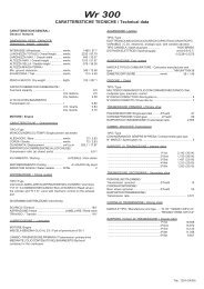
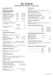
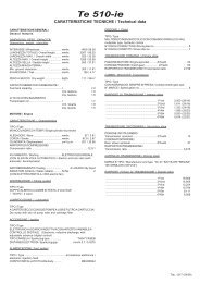
<strong>TE</strong>CHNICAL DATAENGINEType .....................................................single cylinder, 4 strokeCooling.......................liquid with electric fan on <strong>TE</strong>-SMR modelsBore (<strong>310</strong>)................................................................3,27 in.Bore (<strong>450</strong>-<strong>510</strong>)..............................................................3.81 in.Stroke (<strong>310</strong>) ..............................................................2.17 in.Stroke (<strong>450</strong>) .................................................................2.39 in.Stroke (<strong>510</strong>)..................................................................2.67 in.Displacement (<strong>310</strong>) .............................................18,16 cu. in.Displacement (<strong>450</strong>)................................................27.39 cu. in.Displacement (<strong>510</strong>) ................................................30.56 cu. inCompression ratio...........................................................12,9:1Starting (<strong>TC</strong>)............. kick start (with automatic decompressor)Starting (SMR)...............electric (with automatic decompressor)Starting (<strong>TE</strong>-<strong>TXC</strong>) ...............electric and kick start (with automaticdecompressor)TIMING SYS<strong>TE</strong>MType....................................double overhead camshaft; 4 valveValve clearance (with engine cold)Intake ..........................................................0.004 ÷ 0,006 in.Exhaust........................................................0.006 ÷ 0,008 in.LUBRICATIONType .......Dry sump with two oil pump rotor and cartridge filterIGNITIONType ...........Electronic, inductive (<strong>TE</strong>-SMR) or capacitive (<strong>TC</strong>-<strong>TXC</strong>)discharge, with adjustable advance (digital control)Spark plug type ......................................................NGK CR8EBSpark plug gap...........................................................0.027 in.FUEL SYS<strong>TE</strong>MType (<strong>TE</strong>-SMR) .................................................Electronic injection feedType (<strong>TC</strong> <strong>450</strong>, <strong>TXC</strong> <strong>450</strong>-<strong>510</strong>) .Keihin” FCR-MX 41 with acceleration pumpand throttle position sensorVenturi diameter ......................................................................1.61 in.High speed jet ...............................................................................180Low speed jet .................................................................................45Starting jet .....................................................................................85Starting air jet. .........................................................................0.16 in.Main air jet ...................................................................................200Low air jet .....................................................................................100Floater ......................................................................................g 11.2Throttle piston..............................................................................15 MMetering pin ............................................................................OBDVRMetering pin slot ............................................................................5thIdle mixture adjusting screw ................................................. rounds 2PRIMARY DRIVEDrive pinion gear- Clutch ring gear (<strong>TE</strong> <strong>310</strong>)...............................Z 24- Z 88Drive pinion gear- Clutch ring gear (<strong>450</strong>-<strong>510</strong>)............................Z 23- Z 63Transmission ratio (<strong>310</strong>)...................................................................3,666Transmission ratio (<strong>450</strong>-<strong>510</strong>)............................................................2,739CLU<strong>TC</strong>HType...............................oil bath multiple disc clutch, hydraulic controlTRANSMISSIONType ...............................................................constant mesh gear typeTransmission ratio (<strong>TE</strong>-SMR-<strong>TXC</strong>)1st gear......................................................................2,000 (z 28/14)2nd gear .....................................................................1,611 (z 29/18)3rd gear .....................................................................1,333 (z 24/18)4th gear .....................................................................1,086 (z 25/23)5 th gear....................................................................0,920 (z 23/25)6 th gear ....................................................................0,814 (z 22/27)Transmission ratio (<strong>TC</strong>)1st gear......................................................................1,866 (z 28/15)2nd gear ....................................................................1,444 (z 26/18)3rd gear ....................................................................1,263 (z 24/19)4th gear. ....................................................................1,086 (z 25/23)5 th gear. ...................................................................0,954 (z 21/22)SECONDARY DRIVETransmission sprocket- Rear wheel sprocket (<strong>TE</strong> <strong>310</strong>).............Z 13- Z 50Transmission sprocket- Rear wheel sprocket (<strong>TE</strong>-<strong>TXC</strong> <strong>450</strong>-<strong>510</strong>)...Z 13- Z 47Transmission sprocket- Rear wheel sprocket (<strong>TC</strong> <strong>450</strong>) ............Z 14- Z 50Transmission sprocket- Rear wheel sprocket (SMR <strong>450</strong>-<strong>510</strong>)...Z 15- Z 42Transmission ratio (<strong>TE</strong> <strong>310</strong>).........................................................3,846Transmission ratio (<strong>TE</strong>-<strong>TXC</strong> <strong>450</strong>-<strong>510</strong>). ...........................................3,615Transmission ratio (<strong>TC</strong> <strong>450</strong>). .......................................................3,571Transmission ratio (SMR <strong>450</strong>-<strong>510</strong>).............................................. 2,8008
FINAL RATIOS1st gear (<strong>TE</strong> <strong>310</strong>) . . . . . . . . . . . . . . . . . . . . . . . . . . . . . .28,2051st gear (<strong>TE</strong>-<strong>TXC</strong> <strong>450</strong>-<strong>510</strong>) . . . . . . . . . . . . . . . . . . . . . .19,8061st gear (<strong>TC</strong> <strong>450</strong>) . . . . . . . . . . . . . . . . . . . . . . . . . . . . . .18,2611st gear (SMR <strong>450</strong>-<strong>510</strong>) . . . . . . . . . . . . . . . . . . . . . . . .15,3392nd gear (<strong>TE</strong> <strong>310</strong>) . . . . . . . . . . . . . . . . . . . . . . . . . . . . .22,7212nd gear (<strong>TE</strong>-<strong>TXC</strong> <strong>450</strong>-<strong>510</strong>) . . . . . . . . . . . . . . . . . . . . .15,9552nd gear (<strong>TC</strong> <strong>450</strong>) . . . . . . . . . . . . . . . . . . . . . . . . . . . . .14,1302nd gear (SMR <strong>450</strong>-<strong>510</strong>) . . . . . . . . . . . . . . . . . . . . . . .12,3563rd gear (<strong>TE</strong> <strong>310</strong>) . . . . . . . . . . . . . . . . . . . . . . . . . . . . .18,8033rd gear (<strong>TE</strong>-<strong>TXC</strong> <strong>450</strong>-<strong>510</strong>) . . . . . . . . . . . . . . . . . . . . .13,2043rd gear (<strong>TC</strong> <strong>450</strong>) . . . . . . . . . . . . . . . . . . . . . . . . . . . .12,3573rd gear (SMR <strong>450</strong>-<strong>510</strong>) . . . . . . . . . . . . . . . . . . . . . . .10,2264th gear (<strong>TE</strong> <strong>310</strong>) . . . . . . . . . . . . . . . . . . . . . . . . . . . . . .15,3294th gear (<strong>TE</strong>-<strong>TXC</strong> <strong>450</strong>-<strong>510</strong>) . . . . . . . . . . . . . . . . . . . . .10,7644th gear (<strong>TC</strong> <strong>450</strong>) . . . . . . . . . . . . . . . . . . . . . . . . . . . . .10,6334th gear (SMR <strong>450</strong>-<strong>510</strong>) . . . . . . . . . . . . . . . . . . . . . . . .8,3365th gear (<strong>TE</strong> <strong>310</strong>) . . . . . . . . . . . . . . . . . . . . . . . . . . . . .12,9745th gear (<strong>TE</strong>-<strong>TXC</strong> <strong>450</strong>-<strong>510</strong>) . . . . . . . . . . . . . . . . . . . . . . .9,1115th gear (<strong>TC</strong> <strong>450</strong>) . . . . . . . . . . . . . . . . . . . . . . . . . . . . . .9,3385th gear (SMR <strong>450</strong>-<strong>510</strong>) . . . . . . . . . . . . . . . . . . . . . . . ..7,0566th gear (<strong>TE</strong> <strong>310</strong>) . . . . . . . . . . . . . . . . . . . . . . . . . . . . .11,4916th gear (<strong>TE</strong>-<strong>TXC</strong> <strong>450</strong>-<strong>510</strong>) . . . . . . . . . . . . . . . . . . . . . .8,0696th gear (SMR <strong>450</strong>-<strong>510</strong>) . . . . . . . . . . . . . . . . . . . . . . . .6,249FRAMEType.......Steel single tube cradle (roud, rectangular, ellipsoidaltubes); light alloy rear frameFRONT SUSPENSIONType . ”Upside-down” telescopic hydraulic front fork with advancedaxle (adjustable in compression and reboundstroke);a) USA-AUS model excluded: stanchions tubes Ø 1.89 in. (<strong>TE</strong><strong>450</strong>-<strong>510</strong>, <strong>TC</strong> <strong>450</strong>) or Ø 1.97 in. (<strong>TE</strong> <strong>310</strong>, SMR <strong>450</strong>-<strong>510</strong>);b) USA-AUS model: stanchions tubes Ø 1.89 in. (<strong>TE</strong> <strong>310</strong>-<strong>450</strong>-<strong>510</strong>, <strong>TC</strong> <strong>450</strong>) or Ø 1.97 in. (SMR <strong>450</strong>-<strong>510</strong>);Legs axis stroke..................(<strong>TE</strong>, <strong>TC</strong>, <strong>TXC</strong>) 11.8 in.; (SMR) 9.84 in.REAR SUSPENSIONType ...............progressive with hydraulic single shock absorberWheel stroke (<strong>TC</strong>-<strong>TXC</strong>-<strong>TE</strong>)................................................11.6 in.Wheel stroke (SMR).......................................................11.4 in.FRONT BRAKETypefixed disc Ø 10.23 mm “Wave” type with hydraulic controland floating caliper (<strong>TE</strong>, <strong>TC</strong>); floating disc Ø 12.59 mm “Wave”type with hydraulic control and fixed radial caliper (SMR)REAR BRAKEType.... floating disc, ø 9.45 in. “Wave type with hydraulic controland floating caliperRIMSFront (<strong>TE</strong>, <strong>TC</strong>, <strong>TXC</strong>).......TAKASAGO “Excel” in light alloy: 1,6x21”Front (SMR) ...........................SANREMO in light alloy: 3,50x17”Rear (<strong>TE</strong>, <strong>TXC</strong>) ............TAKASAGO “Excel”in light alloy: 2,15x18”Rear (<strong>TC</strong>).........TAKASAGO “Excel” in light alloy: 1,85x19”(250);2,15x19”(<strong>450</strong>-<strong>510</strong>)Rear (SMR) .............................SANREMO in light alloy 4,25x17”TIRESFront(<strong>TE</strong>, USA model excluded -<strong>TXC</strong>) . . . . Michelin ENDUROCOMP. 3 or Pirelli MT 83 Scorpion; 90/90x21"(<strong>TE</strong>, USA model). . . . . . . Metzeler MCE Karoo; 90/90x21”(<strong>TC</strong>) . . . Pirelli 51R-MT 32A or Dunlop D756; 80/100 x 21”(SMR) . . . . . . . . Pirelli MTR 21 DRAGON-EVO; 120/70-17”Rear(<strong>TE</strong>, USA model excluded -<strong>TXC</strong>) . . . Michelin ENDURO COMP.3 or Pirelli MT 83 Scorpion; 120/90x18” (<strong>310</strong>);140/80x18” (<strong>450</strong>-<strong>510</strong>);(<strong>TE</strong> USA model) . Metzeler MCE Karoo; 120/90x18” (<strong>310</strong>);140/80x18” (<strong>450</strong>-<strong>510</strong>)(<strong>TC</strong>). . . . . . . . . . . Pirelli NHS (57) MT 32 or Dunlop D756;110/90x19” (<strong>450</strong>)(SMR). . . . . . . . Pirelli MTR 22 DRAGON-EVO; 150/60x17”Cold tire pressure(front <strong>TC</strong>) . . . . . . . . . . . . . . . . . . . . . . . . 0,9÷1,0 Kg/cm2(front <strong>TE</strong>) (*) (<strong>TXC</strong>) . . . . . . . . . . . . . . . . . 0,9÷1,0 Kg/cm2(front <strong>TE</strong>) (%). . . . . . . . . . . . . . . . . . . . . . . . . 1,1 Kg/cm2(front SMR) (*) . . . . . . . . . . . . . . . . . . . . . . . 1,4 kg/cm2(front SMR) (%) rider only . . . . . . . . . . . . . . . 1,8 kg/cm2(front SMR) (%). . . . . . . . . . . . . . . . . . . . . . . 2,0 kg/cm2rider and passenger(rear <strong>TC</strong>). . . . . . . . . . . . . . . . . . . . . . . . . 0,8÷0,9 Kg/cm2(rear <strong>TE</strong>) (*) (<strong>TXC</strong>) . . . . . . . . . . . . . . . . . 0,8÷0,9 Kg/cm2(rear <strong>TE</strong>) (%) . . . . . . . . . . . . . . . . . . . . . . . . . 1,0 Kg/cm2(rear SMR) (*) . . . . . . . . . . . . . . . . . . . . . . . . 1,6 kg/cm2(rear SMR) (%) . . . . . . . . . . . . . . . 2,0 kg/cm2 rider only(rear SMR) (%). . . . . . . . 2,2 kg/cm2 rider and passenger(*) In case of racing use - (%) Road useEN9
DIMENSION, WEIGHT, CAPACITYWheelbase(<strong>TC</strong>-<strong>TE</strong>-<strong>TXC</strong>) . . . . . . . . . . . . . . . . . . . . . . . . . . . . . 58.38 in.(SMR). . . . . . . . . . . . . . . . . . . . . . . . . . . . . . . . . 56.89 in.Overall length(<strong>TC</strong>) . . . . . . . . . . . . . . . . . . . . . . . . . . . . . . . . . . 86.42 in.(<strong>TE</strong>) . . . . . . . . . . . . . . . . . . . . . . . . . . . . . . . . . . 89.25 in.(SMR) . . . . . . . . . . . . . . . . . . . . . . . . . . . . . . . . . 85.16 in.(<strong>TXC</strong>) . . . . . . . . . . . . . . . . . . . . . . . . . . . . . . . . . 85.94 in.Overall width . . . . . . . . . . . . . . . . . . . . . . . . . . . . 32.30 in.Overall height(<strong>TC</strong>-<strong>TE</strong>-<strong>TXC</strong>) . . . . . . . . . . . . . . . . . . . . . . . . . . . . . 50.59 in.(SMR). . . . . . . . . . . . . . . . . . . . . . . . . . . . . . . . . 49.21 in.Saddle height(<strong>TC</strong>). . . . . . . . . . . . . . . . . . . . . . . . . . . . . . . . . . . 38.11 in.(<strong>TE</strong>-<strong>TXC</strong>). . . . . . . . . . . . . . . . . . . . . . . . . . . . . . . . 37.91 in.(SMR ) . . . . . . . . . . . . . . . . . . . . . . . . . . . . . . . . 36.22 in.Minimum ground clearance(<strong>TC</strong>-<strong>TE</strong>-<strong>TXC</strong>). . . . . . . . . . . . . . . . . . . . . . . . . . . . . . 11.81 in.(SMR). . . . . . . . . . . . . . . . . . . . . . . . . . . . . . . . . . 9.64 in.Dry weight(<strong>TC</strong> <strong>450</strong>) . . . . . . . . . . . . . . . . . . . . . . . . . . . . . . lb. 228.2(<strong>TE</strong> <strong>310</strong>) . . . . . . . . . . . . . . . . . . . . . . . . . . . . . . . lb. 235.9(<strong>TE</strong> <strong>450</strong>-<strong>510</strong>) . . . . . . . . . . . . . . . . . . . . . . . . . . . lb. 244.7(SMR <strong>450</strong>-<strong>510</strong>). . . . . . . . . . . . . . . . . . . . . . . . . . lb. 265.7(<strong>TXC</strong> <strong>450</strong>-<strong>510</strong>) . . . . . . . . . . . . . . . . . . . . . . . . . . . lb 238,1Fuel tank capacity (<strong>TE</strong>-SMR, 1.58 Imp. Qt./ 1.9 U.S. Qt. reserveincluded) 1.58 Imp. Gall./ 1.9 U.S. GallCoolant capacity . . . . . . . . . . . . . . . . . 2.0÷2.4 Imp. Pints;. . . . . . . . . . . . . . . . . . . . . . . . . . . . . . . 2.3÷2.7 U.S. PintsTransmission oilOil and oil filter replacement .......Imp. Quarts 1.5, U.S. Quarts 1.8Oil replacement .......................Imp. Quarts 1.3, U.S. Quarts 1.6TABLE FOR LUBRICATION, SUPPLIESEngine, gearbox and primary drive lubricating oilCASTROL POWER 1 RACING 10W-50Engine coolantASTROL MOTORCYCLE COOLANTBrake system fluidCASTROL RESPONSE SUPER DOT 4Clutch fluidGrease lubricationFinal drive chain lubricationCASTROL FORK OIL 10WCASTROL LM GREASE 2CASTROL CHAIN LUBE RACINGFront fork oilMarzocchi: CASTROL SYNTHETIC FORK OIL 5W - Kayaba: KHL15-11Oil for rear shock absorberCASTROL SYNTHETIC FORK OIL 5WElectric contact protectionCASTROL METAL PARTS CLEANERFillers for radiatorAREXONS TURAFALLE LIQUIDO10
CONTROLSFUEL COCK (<strong>TC</strong>-<strong>TXC</strong>)The left-side tap (2) is a screw tap: screw the ring nut (A) toclose the tap, loosen the ring nut to open the tap.WARNING*: Be careful not to touch the hotengine while operating the fuel valve.A fuel filter is incorporated in the fuel valves. Accumulation ofdirt in the filter will restrict the flow of the fuel to the carburetor.Therefore, the fuel filter should be serviced periodically.1 Loosen the input plug (1) on the fuel tank and close the tap;2 Remove the fuel hose (3) from the carburetor and insert thehose in a vessel;3 Open the tap and drain the fuel out of the tank;4 Remove the fuel valve by removing the screws. Wash the fuelscreen filter in cleaning solvent;5 Reassemble the fuel valve in the reverse order of removal.Open the tap and check for leaks.FUEL INJECTION ENGINE (<strong>TE</strong>-SMR)On vehicles which are fitted with a fuel injection engine, thefuel pump is built into the fuel tank and there is no tap mountedon the fuel supply system. The quantity of remaining fuel isindicated on the digital dash-board by the special warninglight (see on page 14).EN1231. Fuel tank cap2. Fuel cock3. Fuel hoseA. Tap ring nutA11
SIDESTANDA sidestand (1) is supplied with every motorcycle.WARNING*: The stand is designed to supportthe weight of the MOTORCYCLE ONLY.Do not sit on the motorcycle using the standfor support as this could cause structuralfailure to the stand and could cause seriousbodily injury.<strong>TC</strong>-<strong>TXC</strong>1Periodically check the side stand (see “Periodical maintenancecard”); check that the springs are not damaged and that theside stand freely moves. If the side stand is noisy, lubricate thefastening pivot (A).FUELRecommended fuel: premium grade unleaded fuel. (R.O.N.98).Note*: Do not continue operation if the enginepings or knocks. The engine will bedamaged and could seize.WARNING*: If "knocking" or "pinging" occurs,try a different brand of gasoline orhigher octane grade.WARNING*: Gasoline is extremelyflammable and can be explosive under certainconditions. Always stop the engine anddo not smoke or allow flames or sparks inthe area where the motorcycle is refueledor gasoline is stored.WARNING*: Do not overfill the tank. Afterrefueling, make sure the tank cap (2) isclosed securely.2121<strong>TE</strong>-SMRA
CARBURETOR CHOKE (<strong>TC</strong>-<strong>TXC</strong>)The starter knob, located on the left side of the carburetor, isused to enrich the mixture during the engine start.Pull out the knob to open the starter, and pull the lever upwardsto close it.The carburetor is equipped with two knobs:COLD START (<strong>TE</strong>-SMR)For a cold start, the models with a fuel injection engine are fittedwith a black knob (3) located on the left of the throttlebody.Pull the knob outwards to open the starter and push inwards toclose.EN1) BLACK KNOB: COLD start (°)2) RED KNOB: WARM start (°)(°) See page 232113
DIGITAL INSTRUMENT, WARNING LIGHTS(<strong>TE</strong>-SMR)The motorcycle is equipped with a digital instrument; on the instrumentare located 3 warning lights too: high beam, blinkersand fuel reserve.1- BLUE warning light “HIGH BEAM”2- GREEN warning light “BLINKERS”3- ORANGE warning light “Fuel reserve”(1,8 l - 1.58 Imp. qt - 1.9 U.S. qt)Turning the ignition key to the position “IGNITION” the instrumentdisplay illuminates (amber colour).NO<strong>TE</strong>S- When linked to the battery, for the first 2 seconds, the instrumentshows the version of the checking SW; after the check,the instrument shows the last planned function.- When the motorcycle engine is OFF, the instrument doesn’talso show its functions.- To select the instrument functions and to set to zero the functions,use the SCROLL knob (A).- The instrument functions are the following, as shown below.1- SPEED / ODO (figure 1, page 14)2- SPEED / CLOCK (figure 2, page 15)3- SPEED / TRIP (figure 3, page 15)4- SPEED / CHRONO (figure 4, page 15)5- SPEED / RPM (engine r.p.m. numerical value) (figure 5, page 16)1- SPEED / ODO (figure 1, page 14).................IMPORTANT:: in case of FUEL INJECTION SYS<strong>TE</strong>M malfunctionon the right side of the instrument display will be displayedthe warning message “FAIL”: (see page 16): in thiscase contact your local HUSQVARNA Dealer.1- SPEED (Km/h or mph) / ODO (figure 1)- SPEED: motorcycle speed- maximum value: 299 Km/h or299 mph;- ODO: odometer- maximum value: 99999 km;To replace kilometers with miles or miles with kilometers proceedas follows:1) set to figure 1, stop the engine and push the knob SCROLL(A);2) turn the ignition key to the IGNITION position, holdingpushed the button SCROLL (A) until the symbol “Km/h”will be displayed;3) then the symbols “Km/h” and “Mph Miles” will be displayedalternatively. Push again the SCROLL (A) buttonwhen the unit you wish to use is displayed.14
2- SPEED / CLOCK (figure 2)- SPEED: motorcycle speedmaximum value: 299 Km/h o 299mph;- CLOCK: clock- Reading from 0:00 to 23:59:59;To reset the clock, push the knob SCROLL (A) for more than 3seconds in order to increase the hours; release the knob andthen, after 3 seconds, it is possible to increase the minutes;3- SPEED / TRIP 1 (figure 3)- SPEED: motorcycle speedmaximum value: 299 Km/h o 299mph- TRIP 1: distance- maximum value: 999.9 km (the data will belost after battery detachment).To setup the TRIP, push the SCROLL (A) button holding down more than 3seconds4- SPEED / CHRONO (STP) (figure 4)- SPEED: motorcycle speedmaximum value: 299 Km/h o 299mph;- STP 1: miles/kilometers covered time;- Reading from 0:00 to 99:59:59 (the data will be lost afterbattery detachment).To activate the function STP 1, push the knob SCROLL (A) formore than 3 seconds.- 1st step: function ON;- 2nd step: stop to the counters;- 3rd step: STP 1 zero-setting; TRIP 1 and AVS 1 data zero-setting;- 4th step: function ON;- 5th step: stop to the counters;.............................and so followingEN15
5- SPEED / DIGITAL RPM (figure 5)- SPEED: velocità- Indicazione max: 299 Km/h o 299 mph- DIGITAL RPM: MIN. 500, MAX. 14250The instrument display shows even then informations of the“Neutral” condition and of any possible “Malfunction” of the FUELINJECTION SYS<strong>TE</strong>M; this last condition is showedwith absolute priority with respect to anyother information.NEUTRAL: if the speed is under 20 Km/h (12,5 mph), the“Neutral” condition the instrument displays the N character beforethe value of the speed.MALFUNCTION: in case of FUEL INJECTION SYS<strong>TE</strong>M malfunctionon the right side of the instrument display will be displayedthe warning message “FAIL”.16
THROTTLE CONTROLThe throttle knob (1), is located on the right hand side of thehandlebar. The position of the throttle control can be adjustedby loosening the two fastenig screws .CAUTIONDo not forget to tighten the screws (A) afterthe adjustment.S<strong>TE</strong>ERING LOCK (<strong>TE</strong>-SMR)The motorcycle is equipped with a steering lock (1) on the R.H.side of the steering head tube.To lock it, procede as follows:turn the handlebar leftwards, place the key in lock and turncounterclockwise. Push the key inwards (if necessary, turn toand from). Turn the key clockwise and remove it from the lock.To unlock the steering lock, reverse the above procedure.ENFRONT BRAKE CONTROLThe brake control lever (2) is located on the right hand side ofthe handlebar. The position of the throttle control can be adjustedby loosening the two fastenig screws .CAUTIONDo not forget to tighten the screws (B) afterthe adjustment.117
R.H. HANDLEBAR COMMUTATOR (<strong>TE</strong>-<strong>TXC</strong>-SMR)The right commutator has the following controls:1) Engine start button3) Engine start - stop switch (<strong>TE</strong>-SMR)<strong>TE</strong>-SMRL.H. HANDLEBAR COMMUTATOR (<strong>TE</strong>-SMR)CONTROLS:1) High beam flash (self cancelling)2) Selection control High beamSelection control Low beam3) Left turn signals (automatic return)Right turn signals (automatic return)To deactivate the turn signals, press the control lever after itsreturning to center.4) Warning hornENGINE STOP BUTTON (<strong>TC</strong>-<strong>TXC</strong>)On the left side of the handlebar, near the clutch control, is locatedthe engine stop button.CLU<strong>TC</strong>H CONTROLThe hydraulic clutch control lever is located on the left-handside of the handlebar and is protected against dirt with a rubberguard.The clutch control position on the handlebar can be adjustedby loosening the lower fastening screw (A).CAUTIONDo not forget to tighten the screw after theadjustment.<strong>TC</strong>-<strong>TXC</strong>1<strong>TXC</strong>118
REAR BRAKE CONTROLThe rear brake control (1) is placed on the right-hand side ofthe motorcycle. On models <strong>TE</strong> and SMR as stop switch, duringthe braking action, causes the rear light to come on.GEAR SHIFT CONTROLThe lever (1) is placed on the left-hand side of the engine. Theoperator must release the lever after each gear change to allowit to return to its central position before another gearchange can be made.Neutral position (N) is between first (low) and second gears.First gear is engaged by pushing the lever downwards; all theother gears are engaged, by pushing the lever upwards.The position of the gear shift lever on the shaft can be variedby:- loosening screw;- pulling lever out;- placing lever in new position on the shaft when the operationis over tighten the screw and then tightening the screw.ENCAUTION*: Do not shift gears without disengagingthe clutch and closing the throttle.The engine could be damaged by overspeedand shock.WARNING*: Do not downshift when travelingat a speed that would force the engineto overrev in the next lower gear, or causethe rear wheel to lose traction.N: NeutralN: Neutral11<strong>TC</strong><strong>TE</strong>-SMR-<strong>TXC</strong>19
RIDINGBEFORE EVERY RIDE MAKE FOLLOWING CHECKSWARNING!Before each ride, to prevent accidents or failures during ride,make sure to go through following list.1. Check all fluidsA. Engine-transmission oil levelB. fuel levelC. coolant levelMake sure all caps are properly adjusted.WARNING*: Don’t remove radiator capwhen hot!2. Check all controlsA. Throttle handgripB. Clutch leverMake sure cables are not damaged and turn smoothly.3. Check brakesLook for brake fluid leaks and worn hoses. Check for properfunctioning.4. Check suspensionsCompress fork and rear suspensions. Look for oil leaks andensure proper functioning.5. Check wheelsCheck spokes and look for worn bearings.Check rims and tyres.Check tyre pressure.6. Check chain rollers and sprocketsCheck wear on chain rollers and sprocketsEnsure chain is correctly adjusted and lubricated.7. Check air filter and intake systemCheck that air filter is cleanCheck all rubber connections and clamps.8. Check exhaust systemCheck hook up, look for cracksCheck muffler.9. Check torqueA. Spark plug (see page 34).B. General check of torque10. Check steering actionCheck bearing play.11. Check the electric system (<strong>TE</strong>- SMR).Start the engine and check that the front and rear lamps,the stop light, the turn signals the cluster warning lightsand the horn are working correctly.WARNING*: Failure to perform these checksevery day before you ride may result inserous damage or a severe accident.RUNNING INBefore using the motorcycle for sporting activities run in theengine for two hours at least to increase the life and the performanceof the engine.During the first half-hour of driving we advise keeping a lowspeed and avoiding sudden accelerations. Never open thethrottle fully.Change the oil and carry out all the necessary maintenance operations.After the first half-hour of driving, lightly increase therev number, but never run the engine at full throttle. Neverkeep low speeds when the high gears are inserted.Slowly drive the motorcycle for two hours before using it forsporting activities.CHECKS WHILE RUNNING IN- SPOKE <strong>TE</strong>NSION OF WHEELS (see page 69);- TIGH<strong>TE</strong>NING OF WHEELS;- FORK PIN TIGH<strong>TE</strong>NING;- CHAIN ADJUSTMENT (see page 49);- S<strong>TE</strong>ERING BEARING PLAY (see page 36);- HANDLEBAR TIGH<strong>TE</strong>NING;- ENGINE GRIP TO FRAME;- SUCTION FITTING GRIP;- HEAD AND CYLINDER NUTS GRIP;OF<strong>TE</strong>N CHECK THE BAT<strong>TE</strong>RY CHARGE CONDITION (see page 78)20
ENGINE START (<strong>TE</strong>-SMR)With cold engine, as after a prolonged inactivity of the motorcycleor in presence of a low external temperature, proceed asfollows:1) set ignition key (1) in IGNITION position (the buzz that youhear when you turn the key to IGNITION is caused by thefuel pump which puts the feeding system under pressure);2) pull the starter knob (2);3) pull the clutch lever (3);4) shift gear pedal (4) in neutral position then release theclutch control lever;5) press the engine start-stop switch (5) then the start button(6). Put the starter knob (2) in its initial position as soon asthe engine is idling. When starting with an alreadywarmed up engine DO NOT USE the starter. When a coldengine has just been started, do not increase revs, to ensurean adequate oil warm-up and circulation.NO<strong>TE</strong>A safety switch is set on the clutch lever support. This switch allowsyou ONLY to start the engine with idle gearbox, or withthe gear engaged and the clutch lever pulled.IMPORTANTNEVER START WITH DISCONNEC<strong>TE</strong>D BAT<strong>TE</strong>RY.EN13<strong>TE</strong>-SMR5<strong>TE</strong>-SMR24<strong>TE</strong>-SMR621
ENGINE START (<strong>TXC</strong>)Make sure the fuel tap is in the OPEN position, then shift gearpedal in neutral position.Pull the starter knob (BLACK knob (2) for cold starting*, REDknob (3) for warm starting), pull the clutch control lever,then press the engine start button (1).Release the clutch control lever.*: after a prolonged inactivity of the motorcycle or in presenceof a low external temperature.STARTING DECOMPRESSORThough the engine is provided with an automatic decompressor,can be necessary, in some cases (carburetor flooding or startingdifficulties due to a battery inadequate charge), to use the manualstarting decompressor on the L.H. side of the handlebar. Inthese cases, pull the lever (5) whilst simultaneously pressingthe starter button, release the lever (5) keeping the buttonpressed and afterwards release the latter as well.In order to adjust the lever decompressor free play (approximately3 mm- 0.12 in.), the lever holder is provided with the adjuster (6);the adjustment can be also effected with the tightener (7) on theR.H. side of the engine (use this tightener if it is not possible to obtainthe correct free play with the adjuster on the handlebar).23<strong>TXC</strong>122
ENGINE START (<strong>TC</strong>-<strong>TXC</strong>)Proceed as follows:1) make sure the fuel tap (A) is in the Open position;2) shift gear pedal (1) in neutral position.3) pull the starter knob (BLACK knob 2 for cold starting*,RED knob 3 for warm starting)4) lower the starter pedal (4) until a certain resistance is noticed(piston at T.D.C.);EN*: after a prolonged inactivity of the motorcycle or in presenceof a low external temperature.A 2<strong>TC</strong><strong>TXC</strong>31<strong>TC</strong>-<strong>TXC</strong>423
5) pull the lever (5) and lower further, by a limited stroke, thepedal until the abovementioned resistance is overcome(surpassing of T.D.C.);6) at this point, release the lever (5) and the pedal (4); 7) in the case of COLD STARTING, completely rotate the throttle(6) twice (in the case of warm starting DO NOT carry outthis operation);<strong>TC</strong>-<strong>TXC</strong><strong>TC</strong>-<strong>TXC</strong>24<strong>TC</strong>-<strong>TXC</strong>4
8) COMPLE<strong>TE</strong>LY lower the pedal (4) until the engine starts.WARM STARTING: BEFORE MOTORCYCLESTARTING, PRESS RED CHOKE KNOB (3) ONCARBURETOR TOWARD THE INSIDE IN ORDERTO DEACTIVA<strong>TE</strong> THE STARTING DEVICE.In case the engine does not start, repeat this procedure.IMPORTANT NO<strong>TE</strong> IN CASE OF COLD STARTS ATLOW <strong>TE</strong>MPERATURESIt is recommended to briefly warm-up the engine at idle until,after having disengaged the starter, there is a normal responsefrom the engine when opening the throttle.In this way the oil can reach all the surfaces needing lubricationand the coolant will reach the necessary temperature forcorrect engine function.Avoid overheating the engine.IMPORTANTNever accelerate the engine after a cold start.WARNING*: Exhaust contains poisonous carbonmonoxide gas. Never run the engine ina closed garage or in a confined area.In the case of using a kick-starter, followcarefully the instructions on the page 23keep in mind the undermentioned note.Kick start pedalWARNING*: This high performance motorcyclecan some times «kick back» stronglywhen you are starting it.Do not attempt to start this motorcycle unlessyou are wearing high top heavy sidedriding boots. You could seriously hurt youleg if the kickstarter kicked back and yourfoot slipped.EN<strong>TC</strong>-<strong>TXC</strong>4 325
HOT START (<strong>TC</strong>-<strong>TXC</strong>)If it is a problem to start the engine when hot, or following afall, proceed as follows:1) the transmission (1) should be placed in neutral;2) pull the RED knob of the starter (2);3) pull the clutch lever (3);4) push the kick-starter pedal (4) to start the vehicle.5) Then release the clutch lever (3).BEFORE MOVING OFF, DEACTIVA<strong>TE</strong> THE REDKNOB (2) OF THE STAR<strong>TE</strong>R ON THE CARBURET-TOR.<strong>TC</strong><strong>TXC</strong>12<strong>TC</strong> 426
STOPPING THE MOTORCYCLE AND THE ENGINE- Close the throttle (1) completely so that the engine will helpslow down the motorcycle.- For normal braking, gradually apply both front and rearbrakes while down shifting (for maximum deceleration, applythe front and rear brakes firmly).- When stopped, pull the clutch lever and shift gear lever (2)in neutral position.- Press the engine stop RED button (3).- <strong>TC</strong>-<strong>TXC</strong>: close the fuel cock (4).- <strong>TE</strong>-SMR: turn towards left the ignition key.WARNING*: Independent use of the front orrear brake may be advantageous undercertain conditions. Use caution when usingthe front brake, especially on slippery surfaces.Improper use of the brakes can leadto a serious crash.WARNING*: In the event of stuck throttle orother malfunction which causes the engineto run uncontrollably, immediately depressthe engine stop button and hold it down.Control the motorcycle by normal use of thebrakes and steering while holding the enginestop button down.EN4<strong>TC</strong>-<strong>TXC</strong><strong>TE</strong>-SMR<strong>TE</strong>-SMR<strong>TC</strong>-<strong>TXC</strong>27
CHECKING THE OIL LEVELKeeping the motorbike level and in a vertical position, check theoil level through the inspection (1) window on the rightcrankcase. Make sure the level is in between the MIN and MAXnotches.To fill up, remove the filler cap (2).Note*: Have this operation made withwarmed-up engine.WARNING*: Be careful not to touch hot engineoil.ENGINE OIL REPLACEMENT AND BAG FIL<strong>TE</strong>RS-FIL-<strong>TE</strong>R CARTRIDGE CLEANING OR REPLACEMENTWARNING*: Be careful not to touch hot engineoil.Drain the oil with WARM ENGINE; proceed as follows:- remove oil filler cap (2);- remove the engine guard (A)- place an oil drain pan under the engine block- remove the oil drain cap (3)- drain the used oil completely then clean the magneto on thecap;- remove the three filters (5), (6) and (7) on the L.H. side ofthe engine, check O-Rings for wear then clean filters with fuel;reassemble using the reverse procedure;- in order to replace the filter cartridge (4), unscrew the threefastening screws then the filter cartridge cover;- after filters replacement, reassemble the drain cap (3), theengine guard (A) then pour the recommended oil quantity.1MAXMIN2A23 428
COOLANT LEVEL CHECKCheck level (1) in right-hand radiator when engine is cold(place the motorcycle so that it is perpendicular to theground). The coolant should be approximately 10 mm abovecells and besides, on <strong>TE</strong>-<strong>TXC</strong> and SMR models, it doesn't exceedthe middle of the expansion tank (2) located in front ofthe rear shock absorber.The radiator cap is provided of two unlocking positions, thefirst being for the previous pressure discharge in the coolingsystem.WARNINGAvoid removing radiator cap when engine ishot, as coolant may spout out and causescalding.WARNING<strong>TE</strong>-SMR: Because the cooling fan (A)can be activated even when the start switchis in OFF position, always keep at a safedistance from the fan vanes.NO<strong>TE</strong>Difficulties may arise in eliminating coolantfrom varnished surfaces. If this occurs,wash off with water.EN1229
REPLACEMENT OF COOLING FLUIDPlace a vessel on the R.H. side of the cylinder, under thecoolant drain screw (1).FIRST remove the screw (1) then SLOWLY open the R.H. radiatorcap; slope the motorcycle on the right side to drain thecoolant easily in the vessel. Reassemble the screw (1).Pour the necessary quantity of coolant in the radiator thenwarm up the engine in order to eliminate any possible air bubble.Periodically check the connecting hoses (see “Periodical maintenancecard”): this will avoid coolant leakages and consequentengine seizure: If hoses (A) show cracks, swelling orhardenings due to sheats desiccation, their replacement shallbe advisable.Check the correct tightening of the clamps (B).1ABBA30
THROTTLE CABLE ADJUSTMENTTo check the correct adjustment of the throttle operate as follows:- remove the upper rubber cap (1);- by moving cable (2) back and forth check for 2 mm. clearance;- should the clearance be incorrect, unblock the counter ringnut(3) and turn the adjusting screw (4) (by unscrewing it,the clearance is reduced, while by screwing screw (4) it isincreased);- tighten the counter ring-nut again (3).NO<strong>TE</strong>In case of throttle control cables (1) and (2) replacement it isnecessary to respect, during reassembly, the measure Á(10mm/0.4 in.), as shown in the picture. Then reassembleguard cover (B) using screw (3) and adjust throttle controlcables on handlebar as described at side.To replace throttle control cables, first remove tha fuel tank.ENWARNING*: Operation with damaged throttlecable could result in an unsafe ridingcondition.WARNING*: Exhaust gas contains poisonouscarbon monoxide gas. Never run the enginein a closed area or in a confined area.31
ADJUSTING THE CARBURETTOR (<strong>TC</strong>-<strong>TXC</strong>)Adjust the carburettor with warm engine and with the throttlein closed position.Work as follows:- Turn slow running adjusting screw (1) on the left side of thebike, , until the engine is turning over at fairly high rpm(turn the screw clockwise to increase the rpm, and anticlockwiseto descrease the rpm).- Turn adjusting screw (2) clockwise until the fully closed positionis reached then turn back 1,5 turns (<strong>TXC</strong> 250) 2,0 turns(<strong>450</strong>-<strong>510</strong>)- progressively loosen adjusting screw (1) to obtain the slowrunning required.ADJUSTING THE IDLE (<strong>TE</strong>-SMR)Adjust the carburetor with warm engine and with the throttlecontrol in closed position. Proceed as follows:- turn the idle speed adjustment screw (3) on the throttlebody, located on the right side of the vehicle, until the idlespeed of 1600 RPM is reached (turn clockwise to increasethe speed and anti-clockwise to reduce the speed).ADJUSTING THE IDLE (<strong>TC</strong>-<strong>TXC</strong>)Adjust the carburetor with warm engine and with the throttlecontrol in closed position. Proceed as follows:- Turn slow running adjusting screw (1) on the left side of thebike, near the fuel cock (turn the screw clockwise to increasethe rpm, and anticlockwise to descrease the rpm).332
SPARK PLUG CHECKUse NGK CR8EB spark plug (2); the gap is 0.027 in.A wider gap may cause difficulties in starting engine and inoverloading coil.A gap that is too narrow may cause difficulties when accelerating,when idling the engine or when performing at lowspeeds.Clean the dirt away from the base of the spark plug before removingit from the cylinder after removing the cap (1).It is very useful to examine the state of the spark plug just afterit has been removed from the engine since the deposits on theplug and the colour of the insulator provide useful indications.Correct heat rating:The tip of the insulator should be dry and the colour should belight brown or grey.High heat rating:In this case, the insulator tip is dry and covered with dark deposits.Low heat rating:In this case, the spark plug is overheated and insulator tip is vitreous,white or grey in colour.CAUTION*: Select a spark plug with a colder orhotter heat range carefully and cautiously. Aspark plug with too hot a heat range maylead to preignition and possible engine damage.A spark plug with too cold a heat rangemay foul as the result of too much carbonbuildup.Before refitting the plug, thoroughly clean theelectrodes and the insulator using a brass-metalbrush.Apply a little graphite grease to the sparkplug thread; fit and screw the spark plug byhand then tighten to the torque of 10÷12 Nm-7.4÷8.9 ft/lb. Loosen the spark plug thentighten it again to the torque of 10÷12 Nm-7.4÷8.9 ft/lb.Spark plugs which have cracked insulators orcorroded electrodes should be replaced.ENVOLTAGE REGULATOR (<strong>TXC</strong>-<strong>TE</strong>-SMR)The voltage regulator (3) is fitted to the right side of the chassis,on the front.12333
AIR FIL<strong>TE</strong>R CHECK (<strong>TC</strong>-<strong>TXC</strong>)Turn rear pin (1) counterclockwise, remove the saddle from thefront afstening screw.<strong>TXC</strong>: Take out the battery (A) and place it sideways on the vehicle.Remove screw (3) and the filter (4). Separate filter (5) fromframe (6).1AIR FIL<strong>TE</strong>R AND CLEANINGWash the filter with a specific detergent (AGIP” Filter cleanfoam air detergent fluid” or similar) then dry it fully (wash filterwith gasoline only in case of necessity).Plunge the filter in special oil for filters (AGIP "Foam air filterprotection oil" or similar), then wring it to drain superfluousoil.CAUTION*: Do not use gasoline or a lowflash-point solvent to clean the element. Afire or explosion could result.CAUTION*: Clean the element in a well ventilatedarea, and do not allow sparks orflames anywhere near the working area.ASSEMBLYTo ensure tight fit, slightly (C) grease filter edge on side facingfilter housing.While re-inserting the filter into its housing, make surs thatpiece (A) is turned upwards and edge (B) is on the left lowerside of the filter case. Reassemble the parts previously removed(battery: connect the positive cable first).CAUTION*: If the element assembly is notinstalled correctly, dirt and dust may enterand the engine resulting in rapid wear ofthe piston rings and cylinder.UPPER SIDE<strong>TC</strong>-<strong>TXC</strong>LEFT SIDEA463534
AIR FIL<strong>TE</strong>R CHECK (<strong>TE</strong>-SMR)Turn rear pin (1) counterclockwise, remove the saddle from thefront afstening screw.Take out the battery (A) and place it sideways on the vehicle.Remove screw (3) and the filter (4). Separate filter (5) fromframe (6).1AIR FIL<strong>TE</strong>R AND CLEANINGWash the filter with a specific detergent (CASTROL FOAM AIRFIL<strong>TE</strong>R CLEANER or similar) then dry it fully (wash filter withgasoline only in case of necessity).Plunge the filter in special oil for filters (CASTROL FOAM AIRFIL<strong>TE</strong>R OIL or similar) then wring it to drain superfluous oil.CAUTION*: Do not use gasoline or a lowflash-point solvent to clean the element. Afire or explosion could result.CAUTION*: Clean the element in a well ventilatedarea, and do not allow sparks orflames anywhere near the working area.ASSEMBLYTo ensure tight fit, slightly (C) grease filter edge on side facingfilter housing.While re-inserting the filter into its housing, make surs thatpiece (A) is turned upwards and edge (B) is on the left lowerside of the filter case. Reassemble the parts previously removed(battery: connect the positive cable first).CAUTION*: If the element assembly is notinstalled correctly, dirt and dust may enterand the engine resulting in rapid wear ofthe piston rings and cylinder.UPPER SIDE<strong>TE</strong>-SMRENLEFT SIDEA463535
S<strong>TE</strong>ERING WHEEL BALL PLAY ADJUSTMENTTo ensure maximum safety, the steering wheel should alwaysbe regulated so that the handlebars steering the motorcycle rotatefreely without play. To check steering wheel adjustment,place kick stand or other support under the engine so that thefront wheel is raised from ground.Place slight pressure on the tips of the handlebars to rotatesteering wheel; the handlebars should also rotate without effort.Stand in front of the motorcycle and grasp the lower end of thefork rods sliders moving them in the direction of their axis. Sesi avverte gioco occorrerà eseguire la regolazione operandocome segue:- loosen steering sleeve nut (1).- Loosen four screws that fix steering head to fork rods (3).Turn the steering ring nut (2) clockwise of the steeringsleeve proper tool, to adjust play properly.- Tighten steering sleeve nut (1) to a torque setting of57,9÷65,1 Lb/ft; (78,4÷88,3 Nm).- Tighten four screws on the steering head (3) to a torque of22,5÷26,5 Nm (16.6÷19.5 Lb/ft).LOCK ADJUSTMENTThe lock can be changed, using the adjusting units on the sidesof the steering tube, as follows: loosen the ring nut (1) andturn the adjusting screw (2) until you have the desired angle,then tighten the ring nut again (1). Change by the sameamount on both sides.CAUTION*: Do not ride a motorcycle withdamaged steering stem bearings. An unsafehandling condition can result.3 112236
ADJUSTMENT OF THE CONTROL LEVER ANDCHECK OF THE FRONT BRAKE FLUID LEVELOn the SMR model the lever position can be adjusted (4adjustments) for any driver hand size. To decrease the leverdistance from the handle grip, turn the adjuster (B)CLOCKWISE. To increase the lever distance from the handlegrip, turn the adjuster (B) COUN<strong>TE</strong>RCLOCKWISE.On the <strong>TE</strong>, <strong>TXC</strong> and <strong>TC</strong> models the adjuster (2), located on thecontrol lever, allows adjusting of the free play (a).Free play (a) must be at least 3 mm (0.1 in.).The level of the fluid in pump reservoir must never be belowthe minimum value (1), which can be checked from the windowon the rear side of the pump body (<strong>TE</strong>, <strong>TC</strong>). For SMR model,check the level on the fluid reservoir.A decrease of the fuel level will let air into the sustem, hencean extension of the level stroke.WARNING*: If the brake lever feels mushywhen it is applied, there may be air in thebrake lines or the brake may be defective.Since it is dangerous to operate the motorcycleunder such conditions, have the brakechecked immediately by an authorizedHUSQVARNA dealer.SMRCAUTION*: Do not spill brake fluid on toany painted surface or lenses.CAUTION*:Do not mix two brands of fluid.Change the brake fluid in the brake line ifyou wish to switch to another fluid brand.CAUTION*: Brake fluid may cause irritation.Avoid contact with skin or eyes. In case ofcontact, flush thoroughly with water andcall a doctor if your eyes were exposed.ENSMR<strong>TE</strong>-<strong>TC</strong>-<strong>TXC</strong>A: to encrease clearanceB: to decrease clearance<strong>TE</strong>-<strong>TC</strong>-<strong>TXC</strong>+A2<strong>TE</strong>-<strong>TC</strong>-<strong>TXC</strong>B-37
REAR BRAKE PEDAL POSITION ADJUSTMENTThe position of the rear foot brake pedal as to the footrest maybe adjusted according to the individual needs. For the adjustingproceed as follows:- loosen the screw (1);- turn the cam (2) in order to adjust the brake pedal idlestroke (A);- the operation done, tighten the screw (1).The adjusting operation carried out, adjust the idle stroke ofthe pedal as follows.REAR BRAKE IDLE STROKE ADJUSTMENTThe rear brake foot pedal should have a (B) 5 mm (0.2 in.)idle stroke before starting the true braking action.Should this not happen, operate as follows:- loosen nut (3);- operate the pump rod (4) to increase or decrease the idlestroke;- tighten nut (3) at the end of the operation.WARNINGWhen the idle stroke figures are not met,the brake pads will be subjected to a fastwear that may bring to the TOTAL BRAKE IN-EFFECTIVENESS.38
CHECKING THE FLUID LEVELThe level (A) must be set between the pump tank notches.ADJUSTMENT OF THE CONTROL LEVER ANDCHECK OF THE HYDRAULIC CLU<strong>TC</strong>H FLUID LEVELFree play (A) must be at least 3 mm (0.1 in.).The lever position can be adjusted for any driver hand size.To decrease the lever distance from the handle grip, rotate theadjuster (B) CLOCKWISE.To increase the lever distance from the handle grip, rotate theadjuster (B) COUN<strong>TE</strong>RCLOCKWISE.To check the fluid level, proceed as follows:- remove screws (1), cover (2) and rubber pump diaphragmon the handlebar clutch control;- by keeping the master cylinder (3) in horizontal position,check the fluid level is NOT BELOW 4 mm (0.16 in.) from theupper surface (D) of the pump body;- if necessary, add fluid until the correct level is reached seeTABLE FOR LUBRICATION-SUPPLIES for the fluid type page10.<strong>TC</strong>-<strong>TXC</strong>CAUTION*: NEVER use brake fluid.Reassembly the removed parts using the reverse procedure.Periodically check the connecting hose (see “Periodical maintenancecard”): if the hose (C) show is bent or cracked, its replacementis advised.EN39
HYDRAULIC CLU<strong>TC</strong>H BLEEDINGProceed as follows:- remove screws (1), cap (2) and rubber pump diaphragm;- remove the bleeding nipple (3);- mount a syringe in the bleeding nipple hole, then refill withfresh fluid see LUBRICATION TABLE on page 12.The fluid level MUST NEVER BE below 4 mm from the top (A)of the clutch pump body (see picture). Reassemble the removedparts.CAUTION *: NEVER use brake fluid.- refill until fluid is discharged from the lower hole (B) on thepump body WITHOUT BUBBLES.40
ADJUSTING THE SUSPENSIONS ACCORDING TOPARTICULAR TRACK CONDITIONSThe following information is a useful guide for setting up thesuspensions according to the road conditions.Always start from the standard calibration before making anychange on the suspensions. Afterwards, increase or decreasethe adjusting clicks one at a time.NO<strong>TE</strong>:When the fork results as either too soft or too hard for any adjustmentconditions, check the oil level inside the forkrod.The level can either be too low or too high. Remember that toomuch oil inside the fork will involve a more frequent airdrainage. When the suspensions do not react to the changes ofcalibration, check that the adjusting units are not blocked.ENHARD GROUNDFork: softer compression adjustment.Shock absorber: softer compression adjustment.The softer adjustment for the two suspensions is also usedboth in compression and in extension when driving at topspeed, in order to have better grip of the tires.SANDY GROUNDFork: have a harder compression adjustment, or replace thestandard spring with a harder one, and make a softer compressionadjustment and a harder extension adjustment at thesame time.Shock absorber: have a harder compression, and expecially aharder extension adjustment. Work on the spring preload tolower the motorcycle rear side.MUDDY GROUNDFork: have a harder compression adjustment, or replace thestandard spring with a harder one.Shock absorber: have a harder compression and extension adjustments,or replace the standard spring with a harder one.Work on the spring preload to lift the motorcycle rear side.We advise replacing the springs of both suspensions to compensatethe weight increase due to the piling of the mud.41
The standard calibrations and the adjustment procedures areshown below.ADJUSTING THE COMPRESSION FORK(<strong>TE</strong> <strong>310</strong>/EU - SMR <strong>450</strong>, <strong>510</strong>)a) Compression (Lower register)Standard calibration: -12 clicks .Remove plug (B) and turn register (A) clockwise until the positionof fully closed is reached then, turn back by the mentionedclicks.To obtain a smoother braking action, turn the registeranticlockwise. Reverse the operation in order to obtain aharder action.b) EX<strong>TE</strong>NSION (upper register)Standard calibration: - 12 clicks.To reset standard calibration turn register (C) clockwise toreach the position of fully closed; then, turn back by the mentionedclicks. To obtain a smoother braking action, turn theregister anticlockwise. Reverse the operation in order to obtaina harder action.c) AIR VENT (to carry out after each competition, or monthly).Set the motorcycle on a central stand and release the fork fullyand loosen the air vent valve (D). Once this operation is over,tighten the valve.WARNING: Never force the adjusting screwsbeyond the maximum opening and closurepositions.a)ABb) <strong>TE</strong>-SMR <strong>TE</strong>-SMRCCD42
OIL FORK LEVELFor the regular fork operation, both legs must be providedwith the necessary oil quantity. Remove the forkrods form thefork to check the oil level inside the forkrods. Work as follows:- remove the power rod caps;- remove springs from the stems letting the oil drop into thelatter;- bring forks to stroke end;- check that the level is at distance “A” below the upper limitof rods.NO<strong>TE</strong>Flexibility index for the serial springs:K=4,8 N/mm (<strong>TE</strong>)K=5 N/mm (SMR)NO<strong>TE</strong>Always replace both the spring and the spacers to keep thepreload value unchanged.ENOIL QUANTITY IN EACH FORK LEG- <strong>TE</strong>: 725 cm 3 (44.2 cu. in.)- SMR: 740 cm 3 (45.1 cu. in.)A=100mm (3.94 in.) - SMRA=120mm (4.72 in.) - <strong>TE</strong>A43
ADJUSTING THE COMPRESSION FORK(<strong>TC</strong> <strong>450</strong>; <strong>TXC</strong> <strong>450</strong>-<strong>510</strong>; <strong>TE</strong> <strong>310</strong>-<strong>450</strong>-<strong>510</strong>)a) Compression (<strong>TC</strong>,<strong>TXC</strong>: upper register; <strong>TE</strong>: Lower register)Standard calibration: -7 clicks (<strong>TC</strong>-<strong>TXC</strong>);Standard calibration: -10 clicks (<strong>TE</strong>);Remove plug (B) and turn register (A) clockwise until the positionof fully closed is reached then, turn back by the mentionedclicks.To obtain a smoother braking action, turn the registeranticlockwise. Reverse the operation in order to obtain aharder action.b) EX<strong>TE</strong>NSION (<strong>TC</strong>-<strong>TXC</strong>: lower register; <strong>TE</strong>: upper register)Standard calibration: - 10 clicks (<strong>TE</strong>).Standard calibration: - 13 clicks (<strong>TC</strong>-<strong>TXC</strong>).To reset standard calibration turn register (C) clockwise toreach the position of fully closed; then, turn back by the mentionedclicks. To obtain a smoother braking action, turn theregister anticlockwise. Reverse the operation in order to obtaina harder action.c) AIR VENT (to carry out after each competition, or monthly).Set the motorcycle on a central stand and release the fork fullyand loosen the air vent valve (D). Once this operation is over,tighten the valve.WARNING: Never force the adjusting screwsbeyond the maximum opening and closurepositions.a)Ab)CD<strong>TC</strong>-<strong>TXC</strong><strong>TC</strong>-<strong>TXC</strong>44
OIL FORK LEVELFor the regular fork operation, both legs must be providedwith the necessary oil quantity. <strong>TE</strong>: remove the forkrods formthe fork to check the oil level inside the forkrods. Work as follows:- remove the power rod caps;- remove springs from the stems letting the oil drop into thelatter;- bring forks to stroke end;- check that the level is at distance of 5.51in below the upperlimit of rods.NO<strong>TE</strong>Flexibility index for the serial springs:K=8.8 N/mm (<strong>TE</strong>)K=9.6 N/mm (<strong>TC</strong>-<strong>TXC</strong>)NO<strong>TE</strong>Always replace both the spring and the spacers to keep thepreload value unchanged.ENOIL QUANTITY IN EACH FORK LEG- <strong>TC</strong>-<strong>TXC</strong>: 352 cm 3 (21.5 cu. in.)- <strong>TE</strong>: 643 cm 3 (39.2 cu. in.)a) b)ACD<strong>TE</strong><strong>TE</strong>45
HANDLEBAR POSITION AND HEIGHT CHANGEThe handlebar position (a) and height (b) can be changed forbetter suiting Your driving requirements. To effect these operations,remove the upper clamp (1) and the lower one (2), afterremoving the fixing srews (3) and (4).a) Handlebar position changeTurn the lower clamp (2) 180° to move forward or backward(10mm- 0.04in.) the handlebar position with respect to theoriginal setup.b) Handlebar height changeRemove the lower spacer (A) then replace the screw (4) with anew one of L=65 mm (2.56 in.) height.Once these operations are completed, tighten the screws (3) to2,75-3,05 kgm (27-30 Nm; 19.9-22 Lb/fts) and the screws (4)to 2,0-2,2 kgm (19,6-21,6 Nm; 14.5-15.9 Lb/fts).A246
ADJUSTING THE SHOCK ABSORBERThe rear shock absorber must be adjusted according to the riderweight and track conditions.Proceed as follows:1. With motorcycle on the stand, measure distance (A).2. Take the normal riding position on the motorcycle with allyour riding apparel.3. With somebody’s help, take the new distance (A).B: axis of the panel screwC: axis of rear wheel pin4. The difference between these two measurements constitutesthe “SAG” of the motorcycle’s rear end.Suggested SAG: 4 in. with cold shock absorber. 3.7 in. withwarmed up shock absorber.5. To get the right SAG according to your weight, adjust theshock absorber spring preload as described at side.WARNING*: Never disassemble shock absorber,which contains highly compressednitrogen. Contact your Dealer for such majorservice. Do not incinerate.ADJUSTING THE SHOCK ABSORBER SPRINGPRELOADProceed as follows:1. First turn counterclockwise fastening rear pin (1) then removesaddle, screws (2) and R.H. side panel (3).EN2347
2. Clean ringnut (1) and adjusting nut (2) of the spring (3).3. Either with a hook wrench or an aluminium punch, loosenthe ringnut .4. Turn the adjusting nut as required.5. When the adjusting operation is over (according to yourweight and riding style), tighten the ringnut. (Torque forboth ringnuts: 5 Kgm; 49 Nm; 36.2 ft/lb).6. Reassemble R.H. side panel and saddle.WARNING*:Be careful not to touch hot exhaustpipe while adjusting the shock abosrber.SHOCK ABSORBER DAMPING ADJUSTMENTAdjustment of the compression stroke is independent from therebound stroke.A) COMPRESSION - Standard calibration:1) Low damping speed:- 15 clicks (± 2 clicks)(register 4)2) High damping speed:- 15 clicks (± 2 clicks)(register 6)To reset the standard calibration, turn upper registers (4) and(6) clockwise until reaching fully closed position.Return then back for the mentioned clicks. In order to obtain asmooth braking action, turn the registers anticlockwise.Reverse the operation in order to obtain a harder braking action.B) EX<strong>TE</strong>NSION - Standard calibration:- 18 clicks (± 2 clicks)To reset the standard calibration, turn lower register (5) clockwiseuntil reaching fully closed position. Return then back forthe mentioned clicks. In order to obtain a smooth brakingaction, turn the register anticlockwise. Reverse the operationin order to obtain a harder braking action.213 46548
CHAIN ADJUSTMENT (Fig. A)Chain should be checked, adjusted and lubricated as per theMaintenance Chart to ensure security and prevent excessivewear. If the chains becomes badly worn or is poorly adjusted(i.e., if it is too loose or too taught), it could escape fromsprocket or break.To adjust the rear chain it is necessary to lower the rear part ofmotorcycle so to line up the drive sprocket axle, the rear swingarm axle and the rear wheel axle as shown on drawing. Thanlet turn three times the rear wheel. Now the chain should notbe tight.Fast adjustment (Fig. B).In the point shown in the figure, fit a bush (a), 35 mm diameter(or alternatively a shim in the same size) and make surethe lower branch (C) of the chain is slightly taut.If it is not, proceed as follows:- on the right side, with a 27 mm Allen screwdriver, loosen thelocking nut (1) of the wheel pin;- with a 12 mm screwdriver, loosen the check nuts (2) on bothchain stretchers and work on the screws (3) to achieve theright tension;- when the adjustment is over, tighten the check nuts (2) andthe wheel pin nut (1).When the adjustment is over check the wheel for alignment.aFig. BCEN1Fig. A23Drive sprocket axleRear swing arm axleRear wheel axle49
CHECKING THE WEAR OF CHAIN, PINION ANDSPROCKETProceed as follows:- fully stretch the chain with the adjusting screws.- mark 20 chain links.- measure the distance “A” between 1st pin center and 21 stpin center.STANDARDWEARLIMIT317,5 mm 323 mm12,5 in 12,72 inCheck the pinion damages or wear and replace it should thewear degree be as the one shown in figure.Remove the wheel and check the wear of the rear sproketteeth. The below figure shows the outline of teeth in normaland excessive wear. Should the sprocket be badly worn out, replaceit by loosening the six fastening screws to the hub.WARNING*: Misalignment of the wheel willresult in abnormal wear and may result inan unsafe riding condition.Note*: In muddy and wet conditions, mudsticks to the chain and sprockets resulting inan overtight chain. The pinion, the chain,and the rear sprocket wheel wear increaseswhen running on muddy ground.LUBRICATING THE CHAINLubricate the chain following these instructions.WARNING * : Never use grease to lubricatethe chain. Grease helps to accumulate dustand mud, which act as abrasive and hepl torapidly wear out the chain, the sprocket,and the crown.Disassembling and cleaningWhen particularly dirty, remove and clean the chain before lubrication.Work as follows:1 - Set a stand or a block under the engine and see that therear wheel is lifted from the ground.Remove: screws (1), transmission sprocket guard (2), clip(3), master link (4) and transmission chain (5);To reassemble, reverse the above procedure.Normal consumptionExcessive consumption50
2 - Check that the chain is neither worn out nor damaged. If therollers or the links are damaged, replace the chain by followingthe instructions given in the Periodical MaintenanceTable.3 - Check that neither the sprocket nor the crown are damaged.4 - Wash and clean the chain as described hereunder.Washing the chain without OR ( * )Wash using either oil or diesel oil. When using gasoline or tricloroetilene,clean and lubricate the chain to prevent oxidation.Washing the chain with OR ( . )Wash using oil, diesel oil, or paraffin oil. Never use gasoline,tricloroetilene, or solvents, as the OR may suffer damages.Use instead special sprays for chains with OR.Lubricating the chain without OR ( * )First dry, then plunge the chain in a bisulphide molybdenumlubricant, or in high viscosity engine oil. Warm up the oil beforeuse.Lubricating the chain with OR ( . )Lubricate all metallic and rubber (OR) elements using a brush,and use engine oil with SAE 80-90 viscosity for the internaland external parts.5 - If the chain has been cut, reassemble using a joint.6 - Assemble the joint spring (a) by turning the closed side tothe chain direction of rotation as shown in figure below.NO<strong>TE</strong>*: Even if all the joints are reusable when in good conditions,for safety purposes we advise using new joints whenreassembling the chain.7 - Accurately adjust the chain as described on page 47.WARNING: The chain oil has NEVER to get incontact with the tires or the rear brakedisk.Chain tension rollers, chain driving roller,chain guide, chain runnerCheck the wear of the above mentioned elements and replacethem when necessary.WARNING*: Check the chain guide alignement,and remember that a bent elementcan cause a rapid wear of the chain. In thiscase, a chain fleeting from the sprocketmay ensue.EN( * ): <strong>TC</strong>( . ): <strong>TE</strong>-<strong>TXC</strong>-SMR1- Chain tension roller2- Chain driving roller3- Chain guide4- Chain slidera- Joint spring51
REMOVING THE FRONT WHEELSet a stand or a block under the engine and see that the frontwheel is lifted from the ground. Loosen the bolts (1) holdingthe wheel axle (2) to the frontfork stanchions.SMR: remove the two screws (A) and the brake caliper.Hold the head of the wheel axle (2) in place, unscrew the bolt(3) on the opposite side; draw the wheel axle out.NO<strong>TE</strong>SDo not operate the front brake lever when the wheel has beenremoved; this causes the caliper piston to move outwards. Afterremoval, lay down the wheel with brake disc on top.<strong>TE</strong>-<strong>TC</strong>-<strong>TXC</strong>1212A<strong>TE</strong>-<strong>TC</strong>-<strong>TXC</strong>13SMR1 3SMR52SMR
REASSEMBLING THE FRONT WHEELFit the L.H. spacer on the wheel hub.<strong>TE</strong>-<strong>TC</strong>-<strong>TXC</strong>: Fit the wheel between the front fork legs so that thebrake disc is fitted into the caliper.SMR: Fit the wheel between the front fork legs.Fit the wheel axle (2) from the R.H. side, after greasing it andpush it to the stop on the L.H. leg; during this operation, thewheel should be turned. Tighten the screw (3) on the fork L.H.side but DO NOT lock it. Now, pump for a while, pushing thehandlebar downwards until you are sure that the fork legs areperfectly aligned.SMRLock: the screws (1) on the R.H. leg (10,4 Nm/ 1,05 Kgm/ 7.7ft-lb), the screw (3) on the L.H. side (51,45 Nm/ 5,25 Kgm/38 ft-lb), the screws (1) on the L.H. leg (10,4 Nm/ 1,05 Kgm/7.7 ft-lb).SMR: fit the brake caliper on the disc; assemble the caliper onits holding plate and tighten the screws (A) at 25,5 Nm/ 2,6Kgm/ 18.8 ft-lb.Check that the brake disc slides between the caliper pads withoutany friction.NO<strong>TE</strong>After reassembly, pump the brake control lever until the padsare against the brake disc.<strong>TE</strong>-<strong>TC</strong>-<strong>TXC</strong>EN121<strong>TE</strong>-<strong>TC</strong>-<strong>TXC</strong>2<strong>TE</strong>-<strong>TC</strong>-<strong>TXC</strong>SMRSMR131 353
REMOVING THE REAR WHEELUnscrew the nut (1) of the wheel pin (3) and extract it. It is notnecessary to unloose the chain adjusters (2); in this way, thechain tension will remain unchanged after the reassembly.Extract the complete rear wheel, by taking care of the spacerslocated at the hub sides.To reassemble, reverse the above procedure remembering toinsert the disc into the caliper.NO<strong>TE</strong>SDo not operate the rear brake pedal when the wheel has beenremoved; this causes the caliper piston to move outwards.After removal, lay down the wheel with brake disc on top.After reassembly, pump the brake control pedal until the padsare against the brake disc.1254
TIRESCare should be taken to keep the tires properly inflated. Seetire data for correct tire inflation pressure (page 11). Replacethe tire if its wear exceeds what is shown on the table below.FRONTMINIMUM HEIGHT OFTHE TREAD3 mm (<strong>TC</strong>,<strong>TE</strong>,<strong>TXC</strong>); 2 mm (SMR)BRAKESThe mayor components are brake master cylinder with its lever(front) or pedal (rear), brakeline, caliper assembly and disc.LEGEND1. Front brake control lever2. Front brake pump with oil reservoir (<strong>TE</strong>, <strong>TC</strong>,<strong>TXC</strong>)2. Front brake pump (SMR)2A. Oil reservoir (SMR)3. Front brake hose4. Front brake caliper5. Front brake disc6. Rear brake oil tank7. Rear brake hose8. Rear brake caliper9. Rear brake disc10. Rear brake pump11. Rear brake control pedalENREAR3 mm (<strong>TC</strong>,<strong>TE</strong>,<strong>TXC</strong>); 2 mm (SMR)6112A1055
BRAKE PADS REMOVAL- Remove springs (1).- Remove pins (2).- Remove pads.CAUTION!Don't operate the brake lever or pedalwhile removing the pads.PADS WEAR (<strong>TE</strong>-<strong>TC</strong>-<strong>TXC</strong>)Inspect pads for wear.Service limit " A" is: 3,8 mm (0.15 in.).If service limit is exceeded, always replace the pads in pairs.PADS WEAR (SMR)a) In front: thickness “A” must never be lower than the onepointed out by the wear control notches.b) At the back: thickness “A” must never be lower than 3,8mm.If service limit is exceeded, always replace the pads in pairs.SMRFRONT2<strong>TE</strong>-<strong>TC</strong>-<strong>TXC</strong>1<strong>TE</strong>-<strong>TC</strong>-<strong>TXC</strong>FRONT211 2REAR56
PADS CLEANINGBe careful that no disc brake fluid or any oil gets on brakepads or discs. Clean off any fluid or oil that inadverently getson the pads or disc with alcohol.Replace the pads with new ones if they cannot be cleaned satisfactorily.PADS INSTALLATION- Install new brake pads.- Reassemble the two pins (2) and the springs (1).WARNING!Do not attempt to ride the motorcycle untilthe brake lever or pedal arefully effective. Pump the brake lever orpedal until the pads are against the discs.The brake will not function on the first applicationof the lever or pedal.EN<strong>TE</strong>-<strong>TC</strong>-<strong>TXC</strong>FRONTSMRFRONT22111 2 REAR57
BRAKE DISC WEARMeasure the thickness of each disc at the point where it hasworn the most. Replace the disc if it has worn past the servicelimit.DISC WARPAGEMeasure disc warpage. Service limit for both discs is 0,15 mm(0.006 in.)Replace the disc if warpage is more than service limit.Disc ThicknessDISCSTANDARD SERVICELIMITFront 3 mm 2,5 mm(<strong>TE</strong>-<strong>TC</strong>-<strong>TXC</strong>) 0.118 in 0.098 inFront 5 mm 4,5 mm(SMR) 0.197 in 0.177 in<strong>TE</strong>-<strong>TC</strong>-<strong>TXC</strong>Rear 4 mm 3,5 mm0.157 in 0.138 in<strong>TE</strong>-<strong>TC</strong>SMR58
DISC CLEANINGPoor braking can also be caused by oil on the disc. Oil orgrease on the disc must be cleaned off with a high flash-pointoil free solvent, such as acetone or lacquer thinner.FLUID CHANGEThe brake fluid should be checked and changed in accordancewith the Periodic Maintenance Chart or whenever it is contaminatedwith dirt or water. Don't change the fluid in the rain orwhen a strong wind is blowing.ENCAUTION!* Use only brake fluid from a sealed container(DOT 4). Never use old brake fluid.* Never allow contaminants (dirt, water,etc.) to enter the brake fluid reservoir.* Don't leave the reservoir cap off anylength of time to avoid moisture contaminationof the fluid.* Handle brake fluid with care because itcan damage paint.* Don't mix two types of fluid for use in thebrake. This lowers the brake fluid boilingpoint and could cause the brake to be ineffective.It may also cause the rubberbrake part to deteriorate.59
To replace the fluid, proceed as follows:- Remove the rubber cap on the bleeding valve (1) or (1A).- Attach a clear plastic hose to the bleeding valve on the brakecaliper and turn the other end of the hose into a container.- Remove fluid reservoir cap (2)or (2A: 21 mm wrench) andthe rubber.- Loosen bleeding valve on the brake caliper.<strong>TE</strong>-<strong>TC</strong>-<strong>TXC</strong>SMR11A60
- Pump with brake lever (3) or brake pedal (3A) in order topush brake fluid out of line.- Close the bleeding valve and fill the reservoir with freshbrake fluid.- Open the bleeding valve, apply the brake using the brakelever or pedal, close the bleeding valve with the brake leveror pedal applied and then quickly release the lever or pedal.- Repeat this operation until the brake line is filled and clearfluid starts coming out of the plastic hose: now close thebleeding valve.- Restore the brake fluid level (A) or (B) then reassemble therubber and the fluid reservoir cap (page 58).After the brake fluid replacement, it is necessary to operatethe braking system bleeding (see pages 60 and 63).EN<strong>TE</strong>-<strong>TC</strong>-<strong>TXC</strong>SMR61
WARNING!Brake fluid quickly ruins painted surfaces;any spilled fluid should be completelywiped up immediately.* Brake fluid may cause irritation. Avoidcontact with skin or eyes. In case of contact,flush thoroughly and call a doctor if youreyes were exposed.Periodically check the connecting hoses (see“Periodical maintenance card”): if thehoses (A) and (B) are worned or cracked,their replacement is advised.FRONT BRAKING SYS<strong>TE</strong>M BLEEDING(<strong>TE</strong>, <strong>TC</strong>, <strong>TXC</strong>)The braking system must be bled after the fluid replacement orwhen, due to air in the circuit, the lever stroke is long andspongy.Proceed as follows:- Remove the rubber cap on the bleeding valve (1).- Attach a clear plastic hose to the bleeding valve on the brakecaliper and turn the other end of the hose into a container(make sure that the end of the hose is submerged in brakefluid during the entire bleeding operation).A1B<strong>TE</strong>-<strong>TC</strong>-<strong>TXC</strong>62
- Remove fluid reservoir cap (2), the rubber and fill the reservoirwith fresh brake fluid.- Open the bleeding valve and pump with brake lever (3) severaltimes until the fluid, clear and without bubbles, comesout of the hose: now close the bleeding valve.-- Restore the brake fluid level (A) then reassemble the rubberand the fluid reservoir cap (2).WARNING!During the bleed operation the fluid levelinside the reservoir must never be lowerthan the minimum level.Tightening torque for bleed valve is 1,2 ÷1,6 kgm (12 ÷ 16 Nm; 8.8 ÷ 11.8 ft-lb).As the braking fluid is a very corrosivesubstance, in the case it comesin contact with your eyes wash themabundantly with water.During the bleeding of the brakingcircuit keep the handlebar turnedleftwards. This is the way to lift thepump tank and to make easier the bleedingof the braking system.If the lever stroke gets stretchy andthe braking action results as poor inthe case of falls during competitions,or after repair work in shops, repeat thebleeding operation described above.As the bleeding operation does notfully eliminate the air inside the circuit,the small quantity of air remaininginside will be eliminated after ashort time of use of the brake. In this casehowever, the action of the lever will beharder and the stroke shorter.EN63
FRONT BRAKING SYS<strong>TE</strong>M BLEEDING (SMR)The braking system must be bled after the fluid replacementor when, due to air in the circuit, the lever stroke is longand spongy.Regarding the front braking system, first proceed to bleed theupper braking system control (bleeding valve 1), thenthe brake caliper (bleeding valve 1A).In both cases, proceed as follows:- Remove the rubber cap on the bleeding valve (1) or (1A).- Attach a clear plastic hose to the bleeding valve on the brakecaliper and turn the other end of the hose into a container(make sure that the end of the hose is submerged in brakefluid during the entire bleeding operation).- Remove fluid reservoir cap (2), the rubber and fill the reservoirwith fresh brake fluid.- Open the bleeding valve and pump with brake lever severaltimes until the fluid, clear and without bubbles, comes out ofthe hose: now close the bleeding valve.1ASMRSMR64
- Restore the brake fluid level (A) then reassemble the rubberand the fluid reservoir cap.WARNING!During the bleed operation the fluid levelinside the reservoir must never be lowerthan the minimum level.Tightening torque for bleed valve is 1,2 ÷1,6 kgm (12 ÷ 16 Nm; 8.8 ÷ 11.8 ft-lb).As the braking fluid is a very corrosivesubstance, in the case it comesin contact with your eyes wash themabundantly with water.During the bleeding of the brakingcircuit keep the handlebar turnedleftwards. This is the way to lift thepump tank and to make easier the bleedingof the braking system.If the lever stroke gets stretchy andthe braking action results as poor inthe case of falls during competitions,or after repair work in shops, repeat thebleeding operation described above.As the bleeding operation does notfully eliminate the air inside the circuit,the small quantity of air remaininginside will be eliminated after ashort time of use of the brake. In this casehowever, the action of the lever will beharder and the stroke shorter.REAR BRAKING SYS<strong>TE</strong>M BLEEDINGThe braking system must be bled after the fluid replacementor when, due to air in the circuit, the pedal stroke is long andspongy.To bleed the system:- Remove the reservoir cover (A) (21 mm wrench) rubber bootand top up with (DOT 4) brake fluid.EN65
- Attach a clear plastic hose to the bleed valve (1) on thecaliper and turn the other end of the hose into a container.- Depress the pedal (2) and keep it full down.- Loosen the bleed union letting out fluid (at first, only air willcome out), then, closing the union slightly.- Release the pedal and wait for a few seconds before repeatingthe operation until only fluid come out of the tube.- Close the bleed union to the prescribed torque and check thefluid level (B) inside the reservoir before reassemblle the cap(1).If the bleeding operation has be done correctly, the pedal willhave no mushy feel. If not, repeat the operation.NO<strong>TE</strong>Should the motorcycle, due to a fall during a competition orshop repairs, show some elasticity of the brake lever stroke,with a subsequent braking efficiency decrease, you'll to repeatthe circuit bleeding as above described.1WARNING!During the bleed operation the fluid levelinside the reservoir must never be lowerthan the minimum level.Tightening torque for bleed valve is 1,2 ÷1,6 kgm (12 ÷ 16 Nm; 8.8 ÷ 11.8 ft-lb).66<strong>TC</strong>
EXHAUST MUFFLER (<strong>TC</strong>-<strong>TE</strong>-<strong>TXC</strong>)The muffler reduces the noise of the exhaust gases, but it is anintegral part of the exhaust as well. As such, its conditions affectthe motorcycle performance.When the noise on the exhaust is too high, it means that thedeadening material set on the holed tube inside the muffler isdeteriorated.WARNING: Check the deadening material afterevery competition and replace it if necessary.REPLACING THE MUFFLER DEADENING MA<strong>TE</strong>RIALFirst turn counterclockwise fastening rear pin (1) then removesaddle, screws (2) and L.H. side panel (3). Using an 8 mm T-shaped spanner on the outside and a 10 mm T-shaped spanneron the inside, remove the locking screw (4) of the muffler.Remove the spring (5) and with an 8 mm T-shaped spanner removethe screw (8); then pull out the muffler.Remove the six rear rivets (6), clamp and the exhaust terminal(7).Remove innner pipe and replace the deadening material.Reassemble L.H. side panel and saddle.NO<strong>TE</strong>: When diffuculties are found in removingthe muffler, lightly beat with a rubberor plastic hammer.EN235684767
EXHAUST MUFFLER (SMR)The muffler reduces the noise of the exhaust gases, but it is anintegral part of the exhaust as well. As such, its conditions affectthe motorcycle performance.When the noise on the exhaust is too high, it means that thedeadening material set on the holed tube inside the muffler isdeteriorated.WARNING*: Check the deadening materialafter every competition and replace it if necessary.REPLACING THE MUFFLER DEADENING MA<strong>TE</strong>RIALRemove the saddle after turning the locking back pin (1) anticlockwise,loosen the screws (2) with an 8-mm T-shaped spannerand remove the side panel (3) (do the same on the rightside). Using an 8 mm T-shaped spanner on the outside and a10 mm T-shaped spanner on the inside, remove the lockingscrew (4) of the muffler. Remove the spring (5) and pull outthe muffler (A) o (B). Remove the four rear rivets (6), clampand the exhaust terminal (7).Remove innner pipe and replace the deadening material.Reassemble L.H. side panel and saddle.NO<strong>TE</strong>*: When diffuculties are found in removingthe muffler, lightly beat with a rubberor plastic hammer.627243B1467ABA568
OVERHAULING THE WHEELSDEFORMATION RIMWHEEL SPOKESThe tables hereunder show the type of control the rim andwheel axle are to be submitted to.Note*: if the rim is badly, it should be replaced.Side skidEccentricitySTANDARDless than 0,5 mm(0.02 in)less than 0,8 mm(0.03 in)MAX.LIMIT2 mm(0,078 in)Check to make sure that all the nipples are tight; tighten themif necessary.Remember that an insufficient stretch jeopardizes the motorcyclestability.For an instant check, use a metal point (for instance, a screwdriver)to beat the spokes with. A live sound accounts for an accuratetightening, while a dull sound means that a new tighteningis necessary.ENWHEEL RIM AXLE BENDINGIf the bending figure is over the allowable max. limit, straightenor replace the axle.If the wheel axle cannot be straightened within the max. limits(0,2 mm - 0,008 in.) stated, replace it.69
ELECTRICAL COMPONENTS LOCATION (<strong>TE</strong>-SMR)The ignition system includes the following elements:- Generator (1), in oil bath, on the inner side of L.H.crankcase cover;- Electronic ignition coil (2) under the fuel tank;- Electronic power unit C.D.I. (3) under the fuel tank;- Voltage regulator (4) under the fuel tank;- Spark plug (5) on the R.H. side of cylinder head;- Starting motor 12V-<strong>450</strong>W (6) behind the cylinder;- Electric start remote control switch (8) on the left side of therear frame.- M.A.Q.S. sensor (pressure, throttle control position, air temperature)(10) on the throttle body.The electric system includes the following elements:- Battery 12V-6Ah (7) under the saddle;- Flashing indicator device (17) on the left side of the rearframe;78- Relay (14) for light and injection system, on the L.H. side ofthe frame;- Relay (14) for the electric fan, on the R.H. side of the frame;- Electric fan (16);14141741452 161 6370
- Two fuses (9) 15A and one (13) 20A, on the right side of therear mudguard;- Fall sensor (11) on the right side of the rear frame;- Coolant temperature sensor (15);- Lambda probe (18);- Headlamp (20) with two filaments bulb of 12V-35/35W andparking light bulb of 12V-5W;- LED back light (21) (except <strong>TE</strong> <strong>310</strong>/Europe);- Back light (21) with 12V-21W stop light, 12V-5W parkinglight (<strong>TE</strong> <strong>310</strong>/Europe);- Turn signals bulb (22) of 12V-10W;- Fuel pump (19) inside the fuel tank.EN112113222122<strong>TE</strong> <strong>310</strong>-EU910 192015221871
ELECTRICAL COMPONENTS LOCATION (<strong>TC</strong>-<strong>TXC</strong>)The ignition system includes the following elements:- Generator (1) on the inner side of L.H. crankcase cover;- Electronic coil (2) and condenser (11; <strong>TXC</strong>) under the fueltank;- Electronic power unit C.D.I. (3) under the fuel tank;- Voltage regulator (4) under the fuel tank;23114172
- Spark plug (5) on the R.H. side of cylinder head;- Starting motor 12V-<strong>450</strong>W (6) behind the cylinder (<strong>TXC</strong>);- Electric start remote control switch (7) on the left side of therear frame (<strong>TXC</strong>);- Potentiometer (10) on the carburettor.The electric system includes the following elements (<strong>TXC</strong>):- Battery 12V-6Ah (8) under the saddle;- Two fuses (9) 20A, on the electric starter contactor (7).EN108659773
BB/BkBkBrBr/BkBr/RBr/WGG/BkG/GrG/RGrGr/BGr/BkOO/BkO/GPkCable colour codingBlueBlue/BlackBlackBrownBrown/BlackBrown/RedBrown/WhiteGreenGreen/BlackGreen/GreyGreen/RedGreyGrey/BlueGrey/BlackOrangeOrange/BlackOrange/GreenPinkRR/BkSbVWW/BW/BkW/GW/RW/VW/YYY/BkY/BrY/GY/OY/SbY/RRedRed/BlackSky blueVioletWhiteWhite/BlueWhite/BlackWhite/GreenWhite/RedWhite/VioletWhite/YellowYellowYellow/BlackYellow/BrownYellow/GreenYellow/OrangeYellow/Sky blueYellow/RedKEY TO ELECTRIC DIAGRAM (<strong>TE</strong> -SMR)1.Electronic power unit 36. Fall sensor2. Alternator37. Fuses3. Voltage regulator38. Power relay4. Rear stop switch39. Power unit interface5. Front stop switch40. M.A.Q.S. (34+24+32)6. Injector7. Instrument8. R.H. front turn indicator9. Front headlamp10. Cooling fan11. L.H. front turn indicator12. Horn13. L.H. commutator14. Turn indicators flasher15. Tail light16. Battery17. Electric start remote control switch18. Starting motor19. Spark plug20. R.H. rear turn indicator21. L.H. rear turn indicator22. Gear shift position sensor23. H.T. coil24. Sensor position throttle control (40)25. R.H. switch26. Ignition switch27. Clutch microswitch28. Speed sensor29. Relay for electric fan30. Direct current relay31. LAMBDA probe32. Air temperature sensor (40)33. Coolant temperature sensor34. Pressure sensor (40)(*): it stops the enginein case of a 35. Fuel pumpfall74
<strong>TE</strong>-SMR713SMR <strong>TE</strong>30 28 28 10 31 26 29 27 35 23 33 391EN982015211134 24 324 5 14 12 6 25 36 37 38 40 22 2 31817164175
BBrBkGGrGr/ROPRSbVWYCable colour codingBlueBrownBlackGreenGreyGrey/RedOrangePinkRedSky blueVioletWhiteYellowKEY TO ELECTRIC DIAGRAM (<strong>TC</strong>-<strong>TXC</strong>)1. Electronic power unit2. Alternator3. Voltage regulator4. Condenser5. Battery6. Electric start remote control switch7. Starting motor8. Spark plug9. Gear shift position sensor10. Electronic coil11. Carburetor throttle position sensor12. Engine stop13. Engine start14. Clutch microswitch76
43219<strong>TC</strong>-<strong>TXC</strong>EN561413121073*: KIT AVVIAMENTO ELETTRICO (<strong>TXC</strong>)*81177
WARNING*: Batteries produce explosivegas, ventilate when charging or using in enclosedspace. When using a battery chargerbefore turning on the charger. This procedureprevents sparks at the battery terminalswhich could ignite any battery gases.ENINDICATIVE VALUES RELATIVE TO THE CHARGING TIME DEPENDING ON BAT<strong>TE</strong>RY STATUSVOLTAGE * (V) % CHARGE CHARGE TIME (THE “AMPERE” RA<strong>TE</strong>D CURRENT TO APPLY IS: 0,1x BAT<strong>TE</strong>RY RA<strong>TE</strong>DCAPACITY)> 12,7 100 _~12,5 75 4h~12,2 50 7h~12,0 25 11h~11,8 0 14h79
HEADLAMP BULBS REPLACEMENT(<strong>TE</strong>-SMR)To gain access to the healamp bulbs, proceede as follows:- remove the upper fastening screw of the the headlamp carrierto the instrument panuel support (A);- push forward the headlamp carrier (B) and pull it towards thehigh (C) in order to uncouple from the two lower supports.- remove the headlamp carrier;- remove the two filaments bulb (7) connector (2) and theboot (3);- remove the screw (6);- release the bulb holding spring (4) and then the bulb itself.To replace the parking light bulb (5) extract it from the insidecover.After replacement, reverse operations for reassembly.TAIL LIGHT (excluded <strong>TE</strong> <strong>310</strong>/Europe)The back light is a LED light.C543AB675 42380
REAR TAIL LIGHT BULB REPLACEMENT(<strong>TE</strong>- SMR)Remove the two fastening screws (1) in the inner side of therear fender and the lens (2).Pull the lamp (3) inside, turn it counterclockwise then removeit from the lamp holder.After replacement, reverse operations for reassembly.NO<strong>TE</strong>S: make sure not to tighten the screwsexcessively.REPLACING THE NUMBER PLA<strong>TE</strong> LAMP(<strong>TE</strong>- SMR)Pull out the number plate lampholder (4) from the back of thevehicle. Pull out the lampholder and the bulb. Rotate the bulb(5) to remove from the lampholder.Once the bulb has been replaced, reverse the above procedure.EN4581
ADJUSTMENT OF HEADLIGHT (<strong>TE</strong>- SMR)When checking the proper orienting of headlight, inflate tiresat right pressure, sat a person on the saddle and place the motorcycleperpendicular with its longitudinal axis 10 meter (33ft) from a wall or screen. Then trace an horizontal line equal tothe height of headlight center and a vertical one in line with itslongitudinal axis.Adjust the preadlamp aiming by turning screw (1) to lower orlift the high beam.If possibile, execute this operation in a shadowy place.When the low beam is on, the upper boundary limit betweendark and lit zone should be 9/10 th of headlight center fromgroud.182
83EN
84EQUIPMENTPos. Code Nr. NAME MODELS1 8000B1747 HEAT GUARD (1) (<strong>TE</strong>-SMR-<strong>TC</strong>-<strong>TXC</strong>)2 800074016 SIDE STAND (1) (<strong>TC</strong>-<strong>TXC</strong>)3 8000H1343 MULTILANGUAGE QUICK MANUAL (1) (<strong>TE</strong>-SMR-<strong>TC</strong>-<strong>TXC</strong>)4 8000A4296 CARBURETOR KIT KEIHIN 41 (1) (<strong>TC</strong>-<strong>TXC</strong> <strong>450</strong>/<strong>510</strong>)5 8000B0157 ENGINE GUARD (1) (<strong>TE</strong>-SMR-<strong>TC</strong>-<strong>TXC</strong>)6 8000H0188 R.H. ENGINE PRO<strong>TE</strong>CTION (1) (<strong>TE</strong>-<strong>TC</strong>-<strong>TXC</strong>)7 8000H0187 L.H. ENGINE PRO<strong>TE</strong>CTION (1) (<strong>TE</strong>-<strong>TC</strong>-<strong>TXC</strong>)8 8000B1530 HOOK KIT FOR RACE STARTING (1) (<strong>TC</strong>-<strong>TXC</strong>)9 8000B1390 PLUG PRO<strong>TE</strong>CTION (1) (<strong>TE</strong>-SMR-<strong>TC</strong>-<strong>TXC</strong>)10 8000H0159 BAT<strong>TE</strong>RY HOLDER (1) (<strong>TE</strong>-SMR-<strong>TXC</strong>)11 8A0065437 R.H. REARVIEW MIRROR (1) (<strong>TE</strong>)8B0065437 L.H. REARVIEW MIRROR (1) (<strong>TE</strong>)8A00H1673 R.H. REARVIEW MIRROR (1) (SMR)8000H1673 L.H. REARVIEW MIRROR (1) (SMR)12 800097615 HUSQVARNA KEY HOLDER (1) (<strong>TE</strong>-SMR)13 8000H1393 BLINKERS KIT (1) (<strong>TE</strong>)8000H1701 BLINKERS KIT (1) (SMR)14 8000H1702 PASSENGER FOOTREST KIT (1) (SMR)15 8000H1394 HAND GUARDS KIT (<strong>TE</strong>)16 8000A1891 BAT<strong>TE</strong>RY 6AH (<strong>TE</strong>-SMR-<strong>TXC</strong>)*8000H0864 BAT<strong>TE</strong>RY 7AH (<strong>TE</strong>-SMR)*17 8000H1700 “USB” MEMORY (<strong>TE</strong>-SMR-<strong>TXC</strong>)*: In alternative
EQUIPMEN<strong>TE</strong>N85
OPTIONAL PARTS LIST (<strong>TE</strong>)Pos. Code Nr. NAME MODELS1* 8A0096837 REAR SPROCKET Z=47 (1) <strong>310</strong>8B0096837 REAR SPROCKET Z=48 (1) <strong>310</strong>-<strong>450</strong>-<strong>510</strong>8C0096837 REAR SPROCKET Z=49 (1) <strong>310</strong>-<strong>450</strong>-<strong>510</strong>8D0096837 REAR SPROCKET Z=50 (1) <strong>450</strong>-<strong>510</strong>2* 800063829 DRIVE SPROCKET Z=14 (1) <strong>310</strong>-<strong>450</strong>-<strong>510</strong>800063827 DRIVE SPROCKET Z=12 (1) <strong>310</strong>-<strong>450</strong>-<strong>510</strong>800063830 DRIVE SPROCKET Z=15 (1) <strong>310</strong>-<strong>450</strong>-<strong>510</strong>3* 8000H0772 LICENCE PLA<strong>TE</strong> HOLDER KIT RACING (1) <strong>310</strong>-<strong>450</strong>-<strong>510</strong>4 8000H0503 ENGINE GASKET KIT (1) <strong>310</strong>8000H0942 ENGINE GASKET KIT (1) <strong>450</strong>-<strong>510</strong>5 8000B0373 ENGINE SEALS KIT (1) <strong>310</strong>8000B0364 ENGINE SEALS KIT (1) <strong>450</strong>-<strong>510</strong>6 800098504 REAR SHOCK ABS. SPRING (K=5,4 Kg/mm) (1) <strong>450</strong>-<strong>510</strong>8000H0076 REAR SHOCK ABS. SPRING (K=5,6 Kg/mm) (1) <strong>310</strong>7 8000H0590 DOUBLE MODE BUTTON (1) <strong>310</strong>-<strong>450</strong>-<strong>510</strong>OPTIONAL PARTS LIST (SMR)Pos. Code Nr. NAME MODELS1* 8A00A4859 REAR SPROCKET Z=43 <strong>450</strong>-<strong>510</strong>8B00A4859 REAR SPROCKETZ=44 <strong>450</strong>-<strong>510</strong>8G00A4859 REAR SPROCKET Z=45 <strong>450</strong>-<strong>510</strong>2* 800063829 DRIVE SPROCKET Z=14 <strong>450</strong>-<strong>510</strong>3* 8000H0772 LICENCE PLA<strong>TE</strong> HOLDER KIT RACING (1) <strong>450</strong>-<strong>510</strong>4 8000A5982 ENGINE GASKET KIT <strong>450</strong>-<strong>510</strong>5 8000B0364 ENGINE SEALS KIT <strong>450</strong>-<strong>510</strong>8* 8000B0591 KICKSTAR<strong>TE</strong>R KIT <strong>450</strong>-<strong>510</strong>OPTIONAL PARTS LIST (<strong>TC</strong>)Pos. Code Nr. NAME MODELS1 8A0096837 REAR SPROCKET Z=47 (1) <strong>450</strong>8B0096837 REAR SPROCKET Z=48 (1) <strong>450</strong>8C0096837 REAR SPROCKET Z=49 (1) <strong>450</strong>2 800063827 DRIVE SPROCKET Z=12 (1) <strong>450</strong>800063828 DRIVE SPROCKET Z=13 (1) <strong>450</strong>800063830 DRIVE SPROCKET Z=15 (1) <strong>450</strong>4 8000H0943 ENGINE GASKET KIT (1) <strong>450</strong>5 8000A5736 ENGINE SEALS KIT (1) <strong>450</strong>6 800098504 REAR SHOCK ABS. SPRING (K=5,4 Kg/mm) (1) <strong>450</strong>OPTIONAL PARTS LIST (<strong>TXC</strong>)Pos. Code Nr. NAME MODELS1 8B0096837 REAR SPROCKET Z=48 (1) <strong>450</strong>-<strong>510</strong>8C0096837 REAR SPROCKET Z=49 (1) <strong>450</strong>-<strong>510</strong>8D0096837 REAR SPROCKET Z=50 (1) <strong>450</strong>-<strong>510</strong>2 800063827 DRIVE SPROCKET Z=12 (1) <strong>450</strong>-<strong>510</strong>800063829 DRIVE SPROCKET Z=14 (1) <strong>450</strong>-<strong>510</strong>800063830 DRIVE SPROCKET Z=15 (1) <strong>450</strong>-<strong>510</strong>3 8000H0219 LICENCE PLA<strong>TE</strong> HOLDER KIT RACING (1) <strong>450</strong>-<strong>510</strong>4 8000H0942 ENGINE GASKET KIT (1) <strong>450</strong>-<strong>510</strong>5 8000B0364 ENGINE SEALS KIT (1) <strong>450</strong>-<strong>510</strong>6 800098504 REAR SHOCK ABS. SPRING (K=5,4 Kg/mm) (1) <strong>450</strong>-<strong>510</strong>7 8000B1546 NOISE REDUCTION DEVICE (1) <strong>450</strong>-<strong>510</strong>11 8000B0452 SILENCER (TITANIUM) (1) <strong>450</strong>-<strong>510</strong>*: For racing only86
OPTIONAL PARTSEN87
APPENDIXAF<strong>TE</strong>R-RACE CHECK POINTSAfter racing, first clean the motorcycle and then inspect the entiremotorcycle, with special attention to the items listed in«MAIN<strong>TE</strong>NANCE» table (Appendix A), such as the air cleaner,carburetor, brakes, etc.Carry out general lubrication, and make adjustment as necessary.STORAGE (<strong>TC</strong>-<strong>TC</strong>XC)When the motorcycle is to be stored for any length of time, isshould be prepared for storage as follows:- Clean the entire motorcycle thoroughly.- first carry out the operation mentioned hereunder, then fillthe tank with fuel mixed with a stabilizer:place the hose (1) in a basin, loosen the drain screw (2) set onthe lower side of the basin, then drain the fuel and tighten thescrew again.WARNINGNever litter the environment with fuel, andlet the engine running in open air, never inclosed rooms.- Lubricate the drive chain and all the cables.- Spray oil on all unpainted metal surfaces to prevent rusting.Avoid getting oil on rubber parts or in the brakes.- Set the motorcycle on a box or stand so that both wheels areraised off the ground. (If this cannot be done, put boards underthe front and rear wheels to keep dampness away fromthe tire rubber).- Tie a plastic bag over the exhaust pipe to prevent moisturefrom entering.- Put a cover over the motorcycle to keep dust and dirt fromcollecting on it.To put the motorcycle back into the use after storage.- Make sure the spark plug is tight.- Fill the fuel tank.- Run the engine to warm the oil then drain the oil.- Put in fresh transmission oil (page 28).- Check all the points listed under the inspection andAdjustment Section (Appendix A).- Lubricate the points (listed in the Lubrication Section(Appendix A).CLEANINGIMPORTANT RECOMMENDATIONPremised that, before the motorcycle washing, it is necessary toprotect opportunely from the water the following parts:a) Rear opening of the muffler;b) Clutch and brake levers, hand grips, handlebar commutators;c) Air cleaner intake;d) Fork head, wheel bearings;e) Rear suspension links,it is necessary ABSOLU<strong>TE</strong>LY TO AVOID THATHIGH PRESSURE JETS OF WA<strong>TE</strong>R OR AIR cometo contact with THE ELECTRICAL PARTS ANDFUEL INJECTION PARTS, especially the electroniccontrol unit (1) and the sensors groupM.A.Q.S. (2) (page 87).188
IMPORTANT RECOMMENDATIONPremised that, before the motorcycle washing, it is necessaryto protect opportunely from the water the following parts:a) Rear opening of the muffler;b) Clutch and brake levers, hand grips, handlebar commutators;c) Air cleaner intake;d) Fork head, wheel bearings;e) Rear suspension links,EN89
it is necessary ABSOLU<strong>TE</strong>LY TO AVOID THATHIGH PRESSURE JETS OF WA<strong>TE</strong>R OR AIR cometo contact with THE ELECTRICAL PARTS andany parts of the INJECTION SYS<strong>TE</strong>M, especiallythe electronic central unit (1) and theM.A.Q.S. unit (2).After washing- Remove the plastic bags, and clean the air cleaner intake.- Lubricate the points listed in the Maintenance Table (Appendix A).- Briefly warm-up the engine- Test the brakes before riding the motorcycle.WARNING*: Never wax or lubricate thebrake disc. Loss of braking and an accidentcould result. Clean the disc with an oillesssolvent such ans acetone. Observe the solventwarnings.1290
PRE -DELIVERY INSPECTIONDescription Operation Pre-delivery Description Operation Pre-deliveryEngine oilCheck levelTwo-stroke mix oil level Check levelCoolantCheck / Restore levelCooling systemCheck for leakageElectric fansCheck operationSpark plugsCheck / ReplaceThrottle body / Carburettor Check and adjustBrakes / Clutch fluid Check levelBrakes / ClutchCheck operationBrakes / ClutchCheck lines for leakageThrottle controlCheck operationThrottle controlCheck / Adjust playChoke controlCheck operationFlexible controls and transm. Check / AdjustDrive chainCheck / Adjust❆ : presenti solo sui motocicli con motore a 2 tempi❆❆ : presente solo su alcuni modelli❏❏❆❏❏❏ ❆ ❆❏❏❏❏❏❏❏❏❏❏TyresSide standSide stand switchElectrical equipmentInstrument panelLights / Visual signalsHornHeadlightIgnition switchLocksScrews and nutsHose clampsGeneral lubricationGeneral testCheck pressureCheck operationCheck operationCheck operationCheck operationCheck operationCheck operationCheck operationCheck operationCheck operationCheck / TightenCheck / Tighten❆ : only for motorcycles with 2 stroke engine❆❆ : only for some models❏❏❏❏❏❏❏❏❏❏❏❏❏❏EN91
NO<strong>TE</strong>S FOR USA/CDN MODELDISCLAIMER OF WARRANTYIN ACCEPTING DELIVERY OF THIS MOTORCYCLE THE BUYER OR TRANSFEREE ACKNOWLEDGES THAT HE HAS THOROUGHLY INSPEC<strong>TE</strong>D THE MOTORCYCLE, AND FURTHER AGREES TO ACCEPTTHE MOTORCYCLE AS IS WITH ALL DEFECTS OR FAULTS, CONCEALED OR OBVIOUS. HE FURTHER AGREES THAT NO WARRANTIES ATTACH, EXPRESS OR IMPLIED, INCLUDING ANY WARRAN-TY OF MERCHANTABILITY OR FITNESS FOR ANY PARTICULAR PURPOSE. THE BUYER OR TRANSFEREE INDEMNIFIES AND HOLDS HARMLESS HUSQVARNA MOTORCYCLES S.R.L.,ITS AGENTS AND EMPLOYEES. FOR ANY FAILURE OF PERFORMANCE, COST OF SERVICE, OR REPAIR. <strong>TC</strong>-<strong>TXC</strong>: THE BUYER FURTHER ACKNOWLEDGES THAT THIS MOTORCYCLE IS NOT IN<strong>TE</strong>ND-ED FOR USE ON PUBLIC STREETS, ROADS, HIGHWAYS, OR TRAILS UNDER PUBLIC JURISDICTION AND THAT USE ON SUCH MAY VIOLA<strong>TE</strong> STA<strong>TE</strong> AND FEDERAL LAW.Noise emission warrantyHUSQVARNA MOTORCYCLES S.R.L.. warrants that this exhaust system, at the time of sale, meets all applicable U.S. EPA Federal noise standards. This warranty extends to the first person who buys this exhaustsystem for purposes other than resale, and to all subsequent buyers.<strong>TE</strong><strong>TC</strong>-<strong>TXC</strong>SMR92
Tampering warningTampering with Noise Control System Prohibited.Federal law prohibits the following acts or causing thereof:(1) The removal or rendering inoperative by any person otherthan for purposes of maintenance, repair, or replacement,of any device or element of design incorporated into anynew vehicle for the purpose of noise control prior to itssale or delivery to the ultimate purchaser or while it is inuse, and(2) the use of the vehicle after such device or element of designhas been removed or rendered inoperative by anyperson.Among those acts presumed to constitute tampering are theacts listed below.1) Removal of, or puncturing the muffler, baffles, header pipesor any other component which conducts exhaust gases.2) Removal or puncturing of any part of the intake system.3) Lack of proper maintenance.4) Replacing any moving part of the vehicle, or parts of theexhaust or intake system, with parts other than those specifiedby the manufacturer.Warning statementThis product should be checked for repair or replacement if themotorcycle noise has increased significantly through use.Otherwise, the owner may become subject to penalties understate and local ordinances.EN93
SPARK ARRES<strong>TE</strong>RThe <strong>TE</strong> (USA), <strong>TXC</strong> <strong>TC</strong> models are equipped with a U.S. ForestService approved spark arrester for maximum efficienty andperformance.“ SPARK ARRES<strong>TE</strong>R” MAIN<strong>TE</strong>NANCE ANDCLEANOUT INSTRUCTIONSProceed as follows:A: First turn counterclockwise fastening rear pin (1) then removesaddle, screws (2) and L.H. side panel (3).Using an 8 mm T-shaped spanner on the outside and a 10mm T-shaped spanner on the inside, remove the lockingscrew (4) of the muffler.B: Remove the spring (5) and with an 8 mm T-shaped spannerremove the screw (8); then pull out the muffler.Note*: If silencer or exhaust are difficult toremove, help to slide them apart by tappinggently with a rubber or plastic hammer.C: remove the six rivets (6) and the endcap (7) from silencer’sbody;D: examinate SPARK ARRES<strong>TE</strong>R conditions and remove, if necessary,carbon particles from the SPARK ARRES<strong>TE</strong>R screen;E: if necessary, inflate air on the SPARK ARRES<strong>TE</strong>R screen, inthe opposite direction in respect of the exhausted gas flow;F: assemble the front endcap on the silencer’s body, mountingthe screws in the correct position, providing a tight connectionbetween endcap and silencer’s body, using, if necessary,a silicone paste;G: re-assemble the silencer on motorbike, then L. H. side paneland saddle.Due to the SPARK ARRES<strong>TE</strong>R position on the silencer, if youneed only to check the SPARK ARRES<strong>TE</strong>R conditions you can:A: disassemble the silencer from motorbike;B: check SPARK ARRES<strong>TE</strong>R conditions simply looking into the silencerfrom front endcap opening;C: if the check is positive, you can proceed in re-assemblingthe silencer on the motorbike;D: if the check is negative, proceed with the maintenance andcleanout procedure.526894347
Tampering Warning:NO<strong>TE</strong>S FOR “AUS” MODELTampering with Noise Control System Prohibited. Federal law prohibits the following acts or causing therefor:1) The removal or rendering inoperative by any person other than for purposes of maintenance, repair, or replacement, of any device or element of design incorporated intoany new vehicle for the purpose of noise control prior to its sale or delivery to the ultimate purchaser or while it is in use, and2) The use of the vehicle after such device or element of design has been removed or rendered inoperative by any person.ENAmong those acts presumed to constitute tampering are the acts listed below.1) Removal of, or puncturing the muffler, baffles, header pipes or any other component which conducts exhaust gases.2) Removal or puncturing of any part of the intake system.3) Lack of proper maintenace.4) Replacing any moving part of the vehicle, or parts of the exhaust or intake system, with parts other than those specified by the manufacturer.This product should be checked for repair or replacement if the motorcycle noise has increased significantly through use. Otherwise, the owner may become subject to penalitiesunder state and local ordinances.<strong>TE</strong><strong>TC</strong>SMR95
ALPHABETIC INDEXPageAAdjusting the carburetor ..............................................................32Adjusting the clutch ......................................................................39Adjusting the driven transmission ................................................49Adjusting the fork ..................................................................42, 44Adjusting the front brake control lever ..................................................37Adjusting the headlamp................................................................82Adjusting the idle ........................................................................32Adjusting the rear brake idle stroke..............................................38Adjusting shock absorber hydraulicbrake ..........................................................................................48Adjusting shock absorber preload spring..................................................47Adjusting the rear brake pedal position ............................................38Adjusting the steering bearing play ..............................................34Adjusting the suspensions accordingto the track special conditions ......................................................41Adjusting the throttle cable ..........................................................31BBattery ........................................................................................78Brakes..........................................................................................55Brake disc cleaning ......................................................................59Brake disc warpage ......................................................................58Brake disc wear............................................................................58Brake pad assembly ....................................................................57Brake pad wear ..........................................................................56Brake pad disassembly ................................................................56CCarburettor ....................................................................................8Carburettor starter........................................................................13Chain lubrication..........................................................................50Checks after every competition ....................................................88Checks during running in..............................................................20Check of air filter ........................................................................34Check of chain, pinion, crown wear ..............................................50Check of clutch fluid level ............................................................39Check of cooling fluid ..................................................................29Check of front brake fluid level ....................................................37Check of engine oil ......................................................................28Check of rear brake fluid level......................................................39Cleaning the air filter ..................................................................34Clutch ..........................................................................................8Clutch control ..............................................................................18Coolant replacement ....................................................................3096Cooling fluid ................................................................................10Control position..............................................................................7DDigital instrument ........................................................................14Driven transmission chain ..............................................................8EEngine assembling fits..................................................................72Electric diagram ....................................................................75, 77Electric elements ..........................................................................70Engine lubrication ........................................................................10Engine oil replacement ................................................................28Engine start (<strong>TC</strong>) ..........................................................................23Engine start (<strong>TE</strong>-SMR) ..................................................................21Engine stop ..................................................................................27FFilling the braking system ............................................................60Fluid change ................................................................................59Fork oil level ..........................................................................43, 45Fuel..............................................................................................14Fuel cock ......................................................................................11Front brake control ......................................................................19Front braking system bleeding ................................................62-64Front fork ......................................................................................9GGearbox control............................................................................19Gearbox outlet pinion ....................................................................8General cleaning ..........................................................................88HHandlebar commutators ..............................................................18Handlebar position change ..........................................................46Headlamp bulbs replacement ......................................................80Hydraulic clutch bleeding ............................................................40IIgnition ......................................................................................11Important notice ............................................................................3Injection ......................................................................................11LLamp light plate replacement ......................................................81Long inactivity ............................................................................88MMotorcycle stop ............................................................................27Muffler on the exhaust ................................................................67OOil filters replacement ..................................................................28Overhauling the wheels ................................................................69PPad cleaning ................................................................................57Parts replacement ..........................................................................3Pilot lights....................................................................................14Preliminary checks ......................................................................20RRear brake control ........................................................................19Rear braking system bleeding ......................................................65Rear pinion ....................................................................................8Rear damper ..................................................................................9Rear taillight bulb replacement ....................................................80Removing the front wheel ............................................................52Removing the rear wheel..............................................................54Running in ..................................................................................21SSteering lock ................................................................................17Side stand ....................................................................................12Spark arrester ..............................................................................94Spark plug ....................................................................................8Spark plug check..........................................................................33Starting decompressor..................................................................22TThrottle control ............................................................................17Tires ........................................................................................9, 55VVehicle identification number ........................................................5Voltage regulator..........................................................................33WWheel pin bending ......................................................................69Wheel spokes ..............................................................................69Wheels ....................................................................................9, 52
APPENDICE AAPPENDIX AAPPENDICE AANHANG AAPÉNDICE AA1
<strong>TE</strong>-<strong>TC</strong>-<strong>TXC</strong> <strong>310</strong>, <strong>450</strong>, <strong>510</strong> - <strong>2010</strong>MOTOCICLO DA COMPETIZIONE, PER USO AGONISTICO: A PIENA PO<strong>TE</strong>NZACOMPETITION MOTORCYCLE, RACING USE: with FULL POWER ENGINEMOTOCYCLE DE COMPÉTITION, POUR USAGE SPORTIF: AVEC LA PLEINE PUISSANCEPARTICOLARE- I<strong>TE</strong>M- PARTICULAIRESCHEMA DI MANU<strong>TE</strong>NZIONE PERIODICA (DA EFFETTUARE PRESSO IL CONCESSIONARIO HUSQVARNA-PERIODIC MAIN<strong>TE</strong>NANCE SCHEDULE (SEE YOUR HUSQVARNA DEALER FOR THESE SERVICES)-ESQUEME ENTRETIEN PERIODIQUE (EFFECTUER PAR LE VOTRE CONCESSIONAIRE HUSQVARNA)TAGLIANDOCOUPONCOUPONDOPO LE PRIME 3ORE-AF<strong>TE</strong>R FIRST3 hours-APRÈS LESPREMIER 3 heuresOGNEVERYTOUS LESTAGLIANDOCOUPONCOUPONOGNIEVERYTOUS LESTAGLIANDOCOUPONCOUPONOGNIEVERYTOUS LESTAGLIANDOCOUPONCOUPONOGNIEVERYTOUS LESTAGLIANDOCOUPONCOUPONOGNIEVERYTOUS LESSOSTITUIRE SENECESSARIOREPLACE IFNECESSARYREMPLACER SINÉCESSAIRE4h MX/8h EN 8h Mx/16h EN 16h MX/32h EN 32h MX/64h EN 40h MX/80h ENC (GIOCOCLEARANCE-C (GIOCO-CLEARANCE-S (#) #VALVOLE- VALVE- SOUPAPESJEAU) (•)JEAU) (•)MOLLE VALVOLE- VALVE SPRING- RESSORTS SOUPAPES C x #SCODELLINI, SEMICONI VALVOLE- VALVE CUP, VALVE HALF CONE- CUVET<strong>TE</strong>S, DEMI-CÔNE SOUPAPES C x #BILANCIERI DI ASPIRAZIONE/SCARICO- ROCKER ARM (INTAKE-EXHAUST)- CULBU<strong>TE</strong>URS D’ASPIRATION ETD’ÉCHAPPEMEN<strong>TC</strong> x #ALBERO A CAMME- CAMSHAFT- ARBRE DISTRIBUTION C #CA<strong>TE</strong>NA DISTRIBUZIONE- VALVE TIMING CHAIN- CHAINE DISTRIBUTION C S #PATTINO CA<strong>TE</strong>NA DISTRIBUZIONE- VALVE TIMING CHAIN SLIDER- GLISSIÈRE CHAINE DISTRIBUTION S #INGRANAGGIO CONDOTTO DISTRIBUZIONE- VALVE TIMING DRIVEN GEAR- ENGRENAGE CONDIUT DISTRIBUTION C x #INGRANAGGIO CONDUTTORE DISTRIBUZIONE- VALVE TIMING DRIVING GEAR- ENGRENAGE CONDUC<strong>TE</strong>URDISTRIBUTIONC x #<strong>TE</strong>NDITORE CA<strong>TE</strong>NA DISTRIBUZIONE- VALVE TIMING CHAIN <strong>TE</strong>NSIONER- <strong>TE</strong>NDEUR CHAINE DISTRIBUTION C #SIS<strong>TE</strong>MA DECOMPRESSORE- STAR<strong>TE</strong>R DECOMPRESSOR SYS<strong>TE</strong>M- SYSTÈME DECOMPRESSEUR DÉMARRAGE C x 22RACCORDO DI ASPIRAZIONE- INTAKE MANIFOLD- RACCORD ADMISSION C S #CILINDRO COMPLETO- CYLINDER ASSY.- CYLINDRE COMPL. C x #PISTONE COMPLETO- PISTON ASSY.- PISTON COMPL. C S #BIELLA MOTORE COMPLETA- CONNECTING ROD ASSY.- BIELLE COMPL. S #CUSCINETTI BASAMENTO- CRANKCASE BEARINGS- ROULEMENTS CAR<strong>TE</strong>RS S #OLIO MOTORE- ENGINE OIL - HUILE MO<strong>TE</strong>UR S S 28POMPA OLIO - OIL PUMP - POMPE HUILE C #FILTRO OLIO/FILTRO A RE<strong>TE</strong>- OIL FIL<strong>TE</strong>R CARTRIDGE/ NET OIL FIL<strong>TE</strong>R- FILTRE HUILE/ FILTRE A RESEAU S, P S, P 28TUBAZIONE LUBRIFICAZIONE POMPA OLIO/BASAMENTO- OIL PUMP/CRANKCASE HOSE- TUYAU POMPE HUILE/CAR<strong>TE</strong>RSC #COPPIA INGRANAGGI TRASM. PRIMARIA- SET OF MA<strong>TC</strong>HED PRIMARY ENGRENAGES TRANSM. PRIMARIE- C #MOZZO FRIZIONE- CLU<strong>TC</strong>H HUB- MOYEAU POR<strong>TE</strong>-DISQUE EMBRAYAGE C x #DISCHI FRIZIONE- CLU<strong>TC</strong>H DISCS- DISQUES EMBRAYAGE C S x #PIATTO SPINGIDISCHI FRIZIONE- CLU<strong>TC</strong>H DISCS PRESSURE PLA<strong>TE</strong>- POUSSE DISQUES EMBRAYAGE C #MOLLE FRIZIONE- CLU<strong>TC</strong>H SPRING- RESSORT EMBRAYAGE C x #CAMPANA FRIZIONE- CLU<strong>TC</strong>H DISCS HOUSING- CAGE EMBRAYAGE C #ASTINA DISINNESTO FRIZIONE- CLU<strong>TC</strong>H DISENGAGEMENT ROD- BILLE COILESSAU DÉBRAYAGE EMBRAYAGE C #PIGNONE USCITA CAMBIO- DRIVE SPROCKET- PIGNON CHAÎNE TRANSMISSION C S x 50INGRANAGGI AVVIAMENTO- STARTING GEARS - ENGRENAGE DÉMARRAGE C x #VEDERE PAGINASEE PAGEVOIR PAGEA2
<strong>TE</strong>-<strong>TC</strong> <strong>310</strong>, <strong>450</strong>, <strong>510</strong> - <strong>2010</strong>KONKURRENZ-MOTORRAD, das Machen EINEN WETTKAMPF MITvon der VERWENDUNG: mit VOLLEM MACHT-MOTORMOTOCICLO DE COMPETICIÓN, PARA USO AGONÍSTICO: A LLENA PO<strong>TE</strong>NCIAWARTUNGSTABELLE (FÜR DIESE KONTROLLEN WENDEN SIE SICH AN IHRENVERTRAGSHÄNDLER HUSQVARNA)- ESQUEMA DE MAN<strong>TE</strong>NIMIENTO PERIODICO (PARAEFECTUAR ESTAS OPERACIONES DIRÍJASE A SU CONCESIONARIO HUSQVARNA)COUPON-CUPÓNCOUPON-CUPÓNCOUPON-CUPÓNCOUPON-CUPÓNCOUPON-CUPÓN<strong>TE</strong>ILE- PARTICULARNACH DER ERS<strong>TE</strong>N 3STUNDEN-DESPUÉS DELAS PRIMERAS 3 horasALLE-CADA ALLE-CADA ALLE-CADA ALLE-CADA ALLE-CADAWECHSELNWENN NÖTIG-SUBSTITUÍR SINECESARIOSIEHE SEI<strong>TE</strong>-VER PAGINA4h MX/8h EN 8h Mx/16h EN 16h MX/32h EN 32h MX/64h EN 40h MX/80h ENVENTIL- VÁLVULASC (BETRIEBSSPIEL-C (BETRIEBSSPIEL -JUEGO) (•)JUEGO) (•)S (#) #VENTILFEDER- RESOR<strong>TE</strong>S VÁLVULAS C x #<strong>TE</strong>LLER, HALB KEGEL- CUBETAS, SEMI-CONOS VÁLVULASC x #KIPPHEBEL (ANSAUGEN-AUSPUFFROHR)- BALANCIN DE ASPIRACIÓN –ESCAPE C x #NOCKENWELLE- EJE DISTRIBUCIÓN C #VENTILS<strong>TE</strong>UERUNGKET<strong>TE</strong>- CADENA DISTRIBUCIÓN C S #VENTILS<strong>TE</strong>UERUNGKET<strong>TE</strong>GLEITBAHN- PLATO CADENA DISTRIBUCIÓN S #VENTILS<strong>TE</strong>UERUNGZAHNRAD- ENGRENAJE CONDUCTO DISTRIBUCIÓN C x #VENTILS<strong>TE</strong>UERUNGANTRIEBSRAD- ENGRENAJE CONDUCTOR DISTRIBUCIÓN C x #VENTILS<strong>TE</strong>UERUNGKET<strong>TE</strong>SPANNER- <strong>TE</strong>NSOR CADENA DISTRIBUCIÓN C #DEKOMPRESSOR- GRUPO DECOMPRESSOR C x 22ANSCHLUSS- EMPALME DE ASPIRACIÓN C S #ZYLINDER KPL.- CILINDRO COMPLETO C x #KOLBEN KPL.- PISTÓN COMPLETO C S #PLEUELSTANGE KPL.- BIELA MOTOR COMPLETA S #GEHAUSELAGER- COJÍNE<strong>TE</strong> DE CAR<strong>TE</strong>R S #MOTORÖL- ACEI<strong>TE</strong> MOTOR S S 28ÖLPUMPE- BOMBA ACEI<strong>TE</strong> C #WECHSELFIL<strong>TE</strong>R/ SIEBFIL<strong>TE</strong>R- FILTRO ACEI<strong>TE</strong> MOTOR/ FILTRO DE RED S, P S, P 28SCHMIERUNGROHR FÜR ÖLPUMPE/GEHAUSE- TUBO LUBRICACIÓN BOMBA ACEI<strong>TE</strong>/BANCADA C #STIRNRADERPAAR- GRUPO ENGREN. TRANSM. PRIMARIA C #KUPPLUNGSCHEIBENHAL<strong>TE</strong>RNABE- CUBO PORTA DISCOS EMBRAGUE C x #KUPPLUNGSCHEIBE- DISCOS EMBRAGUE C S x #KUPPLUNGDRUCKPLAT<strong>TE</strong>- PLATO EMPUJA DISCOS EMBRAGUE C #KUPPLUNGFEDER- RESOR<strong>TE</strong> EMBRAGUE C x #KUPPLUNGKORB- CAMPANA EMBRAGUE C #KUPPLUNGS<strong>TE</strong>UERSTANGE- VARILLA DESEMBRAGUE C #RITZEL- PIÑÓN CADENA C S x 50ANLASSERANTRIEBSRAD- ENGRENAJE DE ARRANQUE C x #ANLASSERHEBEL- PALANCA ARRANQUE L #GANGSCHALTUNGHEBEL- PEDAL MANDO CAMBIO C x 19AA3
<strong>TE</strong>-<strong>TC</strong>-<strong>TXC</strong> <strong>310</strong>, <strong>450</strong>, <strong>510</strong> - <strong>2010</strong>MOTOCICLO DA COMPETIZIONE, PER USO AGONISTICO: A PIENA PO<strong>TE</strong>NZACOMPETITION MOTORCYCLE, RACING USE: with FULL POWER ENGINEMOTOCYCLE DE COMPÉTITION, POUR USAGE SPORTIF: AVEC LA PLEINE PUISSANCEPARTICOLARE- I<strong>TE</strong>M- PARTICULAIRESCHEMA DI MANU<strong>TE</strong>NZIONE PERIODICA (DA EFFETTUARE PRESSO IL CONCESSIONARIO HUSQVARNA-PERIODIC MAIN<strong>TE</strong>NANCE SCHEDULE (SEE YOUR HUSQVARNA DEALER FOR THESE SERVICES)-ESQUEME ENTRETIEN PERIODIQUE (EFFECTUER PAR LE VOTRE CONCESSIONAIRE HUSQVARNA)TAGLIANDOCOUPONCOUPONDOPO LE PRIME 3ORE-AF<strong>TE</strong>R FIRST3 hours-APRÈS LESPREMIER 3 heuresOGNEVERYTOUS LESTAGLIANDOCOUPONCOUPONOGNIEVERYTOUS LESTAGLIANDOCOUPONCOUPONOGNIEVERYTOUS LESTAGLIANDOCOUPONCOUPONOGNIEVERYTOUS LESTAGLIANDOCOUPONCOUPONOGNIEVERYTOUS LESSOSTITUIRE SENECESSARIOREPLACE IFNECESSARYREMPLACER SINÉCESSAIRE4h MX/8h EN 8h Mx/16h EN 16h MX/32h EN 32h MX/64h EN 40h MX/80h ENPEDALE AVVIAMENTO- STARTING PEDAL- LEVIER DÉMARRAGE L #PEDALE COMANDO CAMBIO - CLEAR CONTROL PEDAL - LEVIER COM. DE VI<strong>TE</strong>SSE C 19CANDELA ACCENSIONE - SPARK PLUG - BOUGIE D’ALLUMAGE P S 33PIPETTA CANDELA - SPARK PLUG GAP - PIPET<strong>TE</strong> BOUGIE D’ALLUMAGE C #CARBURATORE- CARBURETOR- CARBURA<strong>TE</strong>UR P R #VALVOLA GAS CARBURATORE- CARBURETOR THROTTLE VALVE - SOUPAPE DE GAZ DU CARBURA<strong>TE</strong>UR C #FILTRO ARIA- AIR FIL<strong>TE</strong>R- FILTRE À AIR P, L 34-35RADIATORI- RADIATORS- RADIA<strong>TE</strong>URS C #TUBAZIONI ACQUA E FASCET<strong>TE</strong>- COOLANT HOSES AND CLAMPS- TUYAU EAU ET COLLIER C 30TUBAZIONE RADIATORI/POMPA ACQUA- RADIATORS HOSE/WA<strong>TE</strong>R PUMP- TUYAU RADIA<strong>TE</strong>URS/POMPE EAU C 30FLUIDO REFRIGERAN<strong>TE</strong>- COOLANT- RÉFRIGÉRANT C x 29PEDANE APPOGGIAPIEDI, PERNI, MOLLE- FOOTRESTS, FOOTREST PINS AND SPRINGS- REPOSE PIEDS, PIVOTS,RESSORTSC x #PERNI FISS. <strong>TE</strong>LAIETTO, PERNI FISS. MOTORE- SADDLE FRAME FAS<strong>TE</strong>NING BOLTS, ENGINE FAS<strong>TE</strong>NING BOLTS-PIVOTS DE FIXATION CADRE SIEGE, PIVOTS DE FIXATION MO<strong>TE</strong>URC C #CAVALLETTO LA<strong>TE</strong>RALE -SIDE STAND - BEGUILLE LA<strong>TE</strong>RALE C 12RULLO GUIDACA<strong>TE</strong>NA, CUSCINETTO- CHAIN GUIDE ROLLER, BEARINGS- AIGUILLE GUIDE-CHAINE, ROULEMENT C 51<strong>TE</strong>STA DI S<strong>TE</strong>RZO, BASE DI S<strong>TE</strong>RZO CON PERNO- S<strong>TE</strong>ERING HEAD, S<strong>TE</strong>ERING CROWN WITH PIN- TÊ<strong>TE</strong>DIRECTION, SOCLE DE DIRECTION AVEC PIVOTL #FORCELLA AN<strong>TE</strong>RIORE- FRONT FORK- FOURCHE AVANT R #ATTACCHI MANUBRIO E FISSAGGI- HANDLEBAR HOLDERS AND FAS<strong>TE</strong>NING SET- DEMI-PALIERS GUIDON AVECFIXAGEC C 46BUSSOLA FORCELLONE POS<strong>TE</strong>RIORE- REAR SWING ARM BUSHINGS- DOUILLE FOURCHE ARRIÉRE C #PATTINO CA<strong>TE</strong>NA POS<strong>TE</strong>RIORE- REAR CHAIN SLIDER- GLISSIÉRE CHAINE ARRIÉRE C x 51BUSSOLE LEVERAGGI SOSPENSIONE POST.- REAR SUSPENSION LINKS BUSHINGS- DOUILLES LEVIERSUSPENSION ARRIÉREC #GUIDACA<strong>TE</strong>NA/COPRICA<strong>TE</strong>NA- REAR CHAIN GUIDE/ REAR CHAIN GUARD- GUIDE CHAINE/ CAR<strong>TE</strong>R DE CHAINE C x 51GABBIE A RULLI PERNO FORCELLONE- REAR SWING ARM PIVOT NEEDLE BEARINGS- CAGE À AIGUILLES PIVOTFOURCHE ARRIÉREL #AMMORTIZZATORE POS<strong>TE</strong>RIORE- REAR SHOCK ABSORBER- AMMORTISSEUR ARRIÉRE R #GABBIE A RULLI, SPINOTTI LEVERAGGI SOSPENSIONE POS<strong>TE</strong>RIORE- REAR SUSPENSION LINKS NEEDLEBEARINGS AND GUDGEON PIN- CAGE À AIGUILLES, AXES LEVIER SUSPENSION ARRIÉREL #COMANDO GAS COMPLETO- THROTTLE CONTROL ASSY.- COMMANDE GAZ COMPL. C, L 31COMANDO FRIZIONE COMPLETO- CLU<strong>TC</strong>H CONTROL ASSY.- COMMANDE EMBRAYAGE COMPL. C (•) R (#) (•): 39VEDERE PAGINASEE PAGEVOIR PAGEA4
<strong>TE</strong>-<strong>TC</strong> <strong>310</strong>, <strong>450</strong>, <strong>510</strong> - <strong>2010</strong>KONKURRENZ-MOTORRAD, das Machen EINEN WETTKAMPF MITvon der VERWENDUNG: mit VOLLEM MACHT-MOTORMOTOCICLO DE COMPETICIÓN, PARA USO AGONÍSTICO: A LLENA PO<strong>TE</strong>NCIAWARTUNGSTABELLE (FÜR DIESE KONTROLLEN WENDEN SIE SICH AN IHREN VERTRAG-SHÄNDLER HUSQVARNA)- ESQUEMA DE MAN<strong>TE</strong>NIMIENTO PERIODICO (PARA EFECTUARESTAS OPERACIONES DIRÍJASE A SU CONCESIONARIO HUSQVARNA)COUPON-CUPÓNCOUPON-CUPÓNCOUPON-CUPÓNCOUPON-CUPÓNCOUPON-CUPÓN<strong>TE</strong>ILE- PARTICULARNACH DER ERS<strong>TE</strong>N 3STUNDEN-DESPUÉS DELAS PRIMERAS 3 horasALLE-CADA ALLE-CADA ALLE-CADA ALLE-CADA ALLE-CADAWECHSELNWENN NÖTIG-SUBSTITUÍR SINECESARIOSIEHE SEI<strong>TE</strong>-VER PAGINA4h MX/8h EN 8h Mx/16h EN 16h MX/32h EN 32h MX/64h EN 40h MX/80h ENZÜNDKERZE- BUJIA ENCENDIDO P S x 33ZÜNDKERZES<strong>TE</strong>CKER- PIPA BUJIA ENCENDIDO C #VERGASER- CARBURADOR P R #VERGASERDROSSELKLAPPE- VALVULA GAS CARBURADOR C #LUFTFIL<strong>TE</strong>R- FILTRO AIRE P, L 34-35KÜHLER- RADIADORES C #WASSERROHR UND SCHELLEN- TUBOS AGUA Y BANDAS C 30ROHR FÜR KÜHLER/WASSERPUMPE- TUBO RADIADORES/BOMBA AGUA C 30KÜHLFLÜSSIGKEIT- LIQUIDO DE ENFRIAMIENTO C x 29FUSSRAS<strong>TE</strong>R, BOLZEN, FEDER- POSAPIES, PERNOS, RESOR<strong>TE</strong>S C x #HIN<strong>TE</strong>RRAHMENBOLZEN, MOTORBOLZEN- TORNILLOS FIJACIÓN BASTIDOR TRASERO, TORNILLOS FIJACIÓNMOTORC C #SEI<strong>TE</strong>NSTÄNDER- HORQUILLA LA<strong>TE</strong>RAL C 12KET<strong>TE</strong>NFÜHRUNGROLLE, LAGER- RODILLO GUÍA-CADENA, COJÍNE<strong>TE</strong> C 53VORDERGABELLENKKOPF, GABELBRÜCKE MIT BOLZEN- CABEZA DE DIRECCIÓN, BASE DE DIRECCIÓN CONPERNOL #VORDERGABEL- HORQUILLA DELAN<strong>TE</strong>RA R #LENKERBÜGELBOLZEN- CABALLE<strong>TE</strong>S DEL MANILLAR CON PERNOS FIJACIÓN C C 46HIN<strong>TE</strong>RGABELBUCHSE- MANGUITOS HORQUILLA TRASERA C #KET<strong>TE</strong>NGLEITBAHN- PLATO CADENA TRASERA C x 53BUCHSE FÜR HEBELWERKHIN<strong>TE</strong>RHAUFHANGUNG- MANGUITOS PALANCAS SUSPENSION TRASERA C #KET<strong>TE</strong>NFÜHRUNG/ KET<strong>TE</strong>NKAS<strong>TE</strong>N- GUÍA-CADENA/ CUBRE-CADENA C x 53NADELKAFIG FÜR HIN<strong>TE</strong>RGABELBOLZEN- COJÍNE<strong>TE</strong> DE RODILLOS PERNO HORQUILLA TRASERA L #HIN<strong>TE</strong>RSTOSSDAMPFER- AMORTIGUADOR TRASERO R #NADELKAFIG UND BOLZEN FÜR HEBELWERKHIN<strong>TE</strong>RHAUFHANGUNG- COJÍNE<strong>TE</strong> DE RODILLOS, PERNOSPALANCAS HORQUILLA TRASERAL #GASGRIFF KPL.- MANDO GAS COMPLETO C, L 31KUPPLUNGS<strong>TE</strong>UERUNG KPL.- MANDO EMBRAGUE COMPLETO C (•) R (•): 39DECOMPRESSORKABEL UND GASGKABEL- CABLES DECOMPRESSOR Y GAS C L x,21-31VORDERE BREMSSCHEIBE- DISCO FRENO DELAN<strong>TE</strong>RO C x 60VORDERBREMSFLÜSSIGKEIT- FLUIDO INSTALACIÓN FRENAN<strong>TE</strong> DELAN<strong>TE</strong>RA C S 37-61AA5
<strong>TE</strong>-<strong>TC</strong>-<strong>TXC</strong> <strong>310</strong>, <strong>450</strong>, <strong>510</strong> - <strong>2010</strong>MOTOCICLO DA COMPETIZIONE, PER USO AGONISTICO: A PIENA PO<strong>TE</strong>NZACOMPETITION MOTORCYCLE, RACING USE: with FULL POWER ENGINEMOTOCYCLE DE COMPÉTITION, POUR USAGE SPORTIF: AVEC LA PLEINE PUISSANCEPARTICOLARE- I<strong>TE</strong>M- PARTICULAIRESCHEMA DI MANU<strong>TE</strong>NZIONE PERIODICA (DA EFFETTUARE PRESSO IL CONCESSIONARIO HUSQVARNA-PERIODIC MAIN<strong>TE</strong>NANCE SCHEDULE (SEE YOUR HUSQVARNA DEALER FOR THESE SERVICES)-ESQUEME ENTRETIEN PERIODIQUE (EFFECTUER PAR LE VOTRE CONCESSIONAIRE HUSQVARNA)TAGLIANDOCOUPONCOUPONDOPO LE PRIME 3ORE-AF<strong>TE</strong>R FIRST3 hours-APRÈS LESPREMIER 3 heuresOGNEVERYTOUS LESTAGLIANDOCOUPONCOUPONOGNIEVERYTOUS LESTAGLIANDOCOUPONCOUPONOGNIEVERYTOUS LESTAGLIANDOCOUPONCOUPONOGNIEVERYTOUS LESTAGLIANDOCOUPONCOUPONOGNIEVERYTOUS LESSOSTITUIRE SENECESSARIOREPLACE IFNECESSARYREMPLACER SINÉCESSAIREVEDERE PAGINASEE PAGEVOIR PAGE4h MX/8h EN 8h Mx/16h EN 16h MX/32h EN 32h MX/64h EN 40h MX/80h ENCAVI DECOMPRESSORE E GAS- THROTTLE AND STARTING DECOMPRESSOR CABLES- CÂBLES DECOMPRESSEURET GAZC L x 22-31DISCO FRENO AN<strong>TE</strong>RIORE- FRONT BRAKE DISC- DISQUE FREIN AVANT C x 58FLUIDO IMPIANTO FRENAN<strong>TE</strong> AN<strong>TE</strong>RIORE- FRONT BRAKE SYS<strong>TE</strong>M FLUID- FLUIDE SYSTÈME DE FREINAGE AVANT C S 37-59DISCO FRENO POS<strong>TE</strong>RIORE- REAR BRAKE DISC- DISQUE FREIN ARRIÉRE C x 58FLUIDO IMPIANTO FRENAN<strong>TE</strong> POS<strong>TE</strong>RIORE- REAR BRAKE SYS<strong>TE</strong>M FLUID- FLUIDE SYSTÈME DE FREINAGEARRIÉREC S 39-59PASTIGLIE FRENI- BRAKE PADS- PASTILLES DU FREINS C x 54TUBAZIONI POMPA/PINZA IMPIANTI FRENANTI- BRAKE SYS<strong>TE</strong>M PUMP/CALIPER HOSES- TUYAU POMPE/ETRIERSYSTÈME DE FREINAGEC 59TUBAZIONI CARBURAN<strong>TE</strong>- FUEL HOSES- TUYAU CARBURANT C S x #MA<strong>TE</strong>RIALE FONOASSORBEN<strong>TE</strong> SILENZIATORE- EXHAUST SILENCER PACKING- MA<strong>TE</strong>RIAL INSONORISANTSILENCIEUX D’ECHAPPEMENTS x 67TUBO DI SCARICO E SILENZIATORE- EXHAUST PIPE AND SILENCER- TUYAU ET SILENCIEUX D’ECHAPPEMENT C x #<strong>TE</strong>NSIONE RAGGI RUO<strong>TE</strong>- WHEEL SPOKES <strong>TE</strong>NSION- <strong>TE</strong>NSION BRAS RUOES C C 69CUSCINETTI MOZZI RUO<strong>TE</strong>- WHEEL HUB BEARINGS- ROULEMENTS MOYEAUS RUOES S x #CORONA POS<strong>TE</strong>RIORE - REAR DRIVE SPROKET - COURONNE ARRIERE S x #SERRAGGIO VITI CORONA- REAR DRIVEN SPROCKET SCREWS TIGH<strong>TE</strong>NING- SERRAGE VIS COURONNE ARRIÉRE C C 50CA<strong>TE</strong>NA TRASMISSIONE SECONDARIA- REAR TRANSMISSION CHAIN- CHAINE ARRIÉRE C, L S x 50SERRAGGIO BULLONERIA- BOLTS AND NUTS TIGHTNESS GENERAL CHECK- SERRAGE DES BOULONS C C #LEGENDA- KEY FOR MAIN<strong>TE</strong>NANCE SCHEDULE- LEGENDEh: ORE- HOURS- HEURESS: SOSTITUZIONE- REPLACEMENT- REMPLACEMEN<strong>TC</strong>: CONTROLLO- CHECK- CONTRÔLEP: PULIZIA- CLEANING- NETTOYAGER: REVISIONE- OVERHAUL- REVISIONL: INGRASSAGGIO/LUBRIFICAZIONE- GREASING/LUBRICATION- LUBRIFICATION/GRAISSAGEMX: MOTOCROSSEN: ENDURO#: VEDERE IL MANUALE DI OFFICINA- SEE WORKSHOP MANUAL- VOIR MANUAL D’A<strong>TE</strong>LIERNO<strong>TE</strong>- NO<strong>TE</strong>- NO<strong>TE</strong>SOSTITUIRE LE GUARNIZIONI IN OCCASIONE DI OGNI SMONTAGGIO- VERY REMOVAL REPLACE ALL GASKETS- TOU<strong>TE</strong>S LES DÉMONTAGES, REMPLACER LES GARNITURESSOSTITUIRE LA VI<strong>TE</strong>RIA IN CASO DI DE<strong>TE</strong>RIORAMENTO- REPLACE SCREWS AND NUTS IF WORN- AU CAS DE DÉTÉRIORATION, REMPLACER LES BOULONSDOPO PERCORRENZE SU FANGO O SABBIA EFFETTUARE UNA VERIFICA GENERALE- GENERAL CHECK AF<strong>TE</strong>R RACING USE ON MUDDY OR SANDY GROUNDS- APRÈS USAGE SUR DES <strong>TE</strong>RREINS BOUEUX OU SABLEUX, EFFECTUER UN CONTRÔLE GENERALA6
<strong>TE</strong>-<strong>TC</strong> <strong>310</strong>, <strong>450</strong>, <strong>510</strong> - <strong>2010</strong>KONKURRENZ-MOTORRAD, das Machen EINEN WETTKAMPF MITvon der VERWENDUNG: mit VOLLEM MACHT-MOTORMOTOCICLO DE COMPETICIÓN, PARA USO AGONÍSTICO: A LLENA PO<strong>TE</strong>NCIAWARTUNGSTABELLE (FÜR DIESE KONTROLLEN WENDEN SIE SICH AN IHRENVERTRAGSHÄNDLER HUSQVARNA)- ESQUEMA DE MAN<strong>TE</strong>NIMIENTO PERIODICO (PARAEFECTUAR ESTAS OPERACIONES DIRÍJASE A SU CONCESIONARIO HUSQVARNA)COUPON-CUPÓNCOUPON-CUPÓNCOUPON-CUPÓNCOUPON-CUPÓNCOUPON-CUPÓN<strong>TE</strong>ILE- PARTICULARNACH DER ERS<strong>TE</strong>N 3STUNDEN-DESPUÉS DELAS PRIMERAS 3 horasALLE-CADA ALLE-CADA ALLE-CADA ALLE-CADA ALLE-CADAWECHSELNWENN NÖTIG-SUBSTITUÍR SINECESARIOSIEHE SEI<strong>TE</strong>-VER PAGINA4h MX/8h EN 8h Mx/16h EN 16h MX/32h EN 32h MX/64h EN 40h MX/80h ENHIN<strong>TE</strong>RE BREMSSCHEIBE- DISCO FRENO TRASERO C x 58HIN<strong>TE</strong>RBREMSFLÜSSIGKEIT- FLUIDO INSTALACIÓN FRENAN<strong>TE</strong> TRASERA C S 39-59BREMSBELAEGE- PASTILLAS FRENOS C x 56BREMSPUMPE/BREMSSÄT<strong>TE</strong>L SCHLAUCH- TUBERÍAS BOMBA/PINZA INSTALACIÓNES FRENAN<strong>TE</strong>S C 59TREIBSTOFFROHR- TUBERÍAS CARBURAN<strong>TE</strong> C S x #GERÄUSCHDÄMPFENDES MA<strong>TE</strong>RIAL FÜR AUSPUFF- MA<strong>TE</strong>RIAL FONOABSORBEN<strong>TE</strong> SILENCIADOR S x 67AUSPUFFROHR UND SCHALLDÄMPFER- TUBO DE ESCAPE Y SILENCIADOR C x #RADSPEICHENSSPANNUNG- <strong>TE</strong>NSION RADIOS RUEDAS C C 69RADNABENLAGER- COJÍNE<strong>TE</strong>S CUBOS RUEDAS S x #KRANZ- CORONA TRASERA S x #SCHRAUBENANZIEHUNG FÜR HIN<strong>TE</strong>RKRANZ- TORSION TORNILLOS CORONA TRASERA C C 50SEKUNDÄRE ÜBERTRAGUNGSKET<strong>TE</strong>- CADENA TRANSMISIÓN SECUNDARIA C, L S x 50KONTROLLE VERSCHRAUBUNG KALTGESENKBOLZEN- CONTROL GENERAL AJUS<strong>TE</strong> TUERCAS C C #ALEGENDE- LEYENDAh: STUNDEN- HORASS: WECHSELN- SUBSTITUCIÓNC: KONTROLLIEREN- CONTROLP: REINIGEN- LIMPIEZAR: REVISION- REVISIONL: SCHMIERUNG/BESCHMEIREN- ENGRESAJE/LUBRICACIÓNMX: MOTOCROSSEN: ENDURO#: SIEHE WERKSTATTHANDBUCH- VER MANUAL DE OFICINAANMERKUNG- NOTASDICHTUNGWECHSE: BEI JEDEM DEMONTAGE- SUBSTITUIR LAS EMPACURAS EN EL CASO DE DESMONTAJESCHRAUBEN VERSCHLEISS: WECHSELN- SUBSTITUIR TORNILLOS Y TUERCAS EN EL CASO DE DESGAS<strong>TE</strong>SCHLAMMIGES UND SANDIGES GELÄNDEN: EIN ALLGEMEINE KONTROLLE DURCHFÜHREN- DESPUÉS DE LA CARRERA SOBRE UN <strong>TE</strong>RRENO FANGOSO O ARENOSO, EFECTUAR UN CONTROL GENERALA7
SMR <strong>450</strong>, <strong>510</strong>- <strong>2010</strong> - <strong>TE</strong> <strong>310</strong>, <strong>450</strong>, <strong>510</strong> - <strong>2010</strong>PARTICOLARE- I<strong>TE</strong>M- PARTICULAIRESMR <strong>450</strong>, <strong>510</strong> - <strong>2010</strong> - <strong>TE</strong> <strong>310</strong>, <strong>450</strong>, <strong>510</strong> - <strong>2010</strong>- MOTOCICLO DI SERIE, PER USO STRADALE (A PO<strong>TE</strong>NZA LIMITATA):SMR <strong>450</strong>, <strong>510</strong>- <strong>2010</strong>; <strong>TE</strong> <strong>310</strong>, <strong>450</strong>, <strong>510</strong> - <strong>2010</strong>- STANDARD MOTORCYCLE, STREET LEGAL (with LIMI<strong>TE</strong>D POWER ENGINE):SMR <strong>450</strong>, <strong>510</strong>- <strong>2010</strong>; <strong>TE</strong> <strong>310</strong>, <strong>450</strong>, <strong>510</strong> - <strong>2010</strong>- MOTOCYCLE DE SÉRIE, POUR USAGE ROUTIER (AVEC LA PUISSANCE LIMITÉ):SMR <strong>450</strong>, <strong>510</strong>- <strong>2010</strong>; <strong>TE</strong> <strong>310</strong>, <strong>450</strong>, <strong>510</strong> - <strong>2010</strong>SMR <strong>450</strong>, <strong>510</strong> - <strong>2010</strong>-MOTOCICLO DA COMPETIZIONE, PER USO AGONISTICO (A PIENA PO<strong>TE</strong>NZA)- COMPETITION MOTORCYCLE, RACING USE (with FULL POWER ENGINE)- MOTOCYCLE DE COMPÉTITION, POUR USAGE SPORTIF (AVEC LA PLEINE PUISSANCE)A8SCHEMA DI MANU<strong>TE</strong>NZIONE PERIODICA (DA EFFETTUARE PRESSO IL CONCESSIONARIO HUSQVARNAPERIODIC MAIN<strong>TE</strong>NANCE SCHEDULE (SEE YOUR HUSQVARNA DEALER FOR THESE SERVICES)ESQUEME ENTRETIEN PERIODIQUE (EFFECTUER PAR LE VOTRE CONCESSIONAIRE HUSQVARNA)TAGLIANDOCOUPONCOUPONDOPO I PRIMI 1000KmAF<strong>TE</strong>R FIRST 1000 KmAPRÈS LES PREMIERS 1000 KmDOPO LE PRIME 3 OREAF<strong>TE</strong>R FIRST 3 hoursAPRÈS LES PREMIERS 3 heuresC (GIOCOCLEARANCE- JEAU) (•)TAGLIANDOCOUPON- COUPONOGNI 5000 KMEVERY 5000 KmTOUS LES 5000 KmOGNI 5 OREEVERY 5 hoursTOUS LES 5heuresC (GIOCO- CLEARANCE-JEAU) (•)TAGLIANDOCOUPONCOUPONOGNI 10000KmEVERY 10000 KmTOUS LES 10000 KmOGNI 15 OREEVERY 15 hoursTOUS LES 15 heuresSOSTITUIRE SENECESSARIOREPLACE IFNECESSARYREMPLACER SINÉCESSAIREVALVOLE- VALVE- SOUPAPESS (#)#MOLLE VALVOLE- VALVE SPRING- RESSORTS SOUPAPES C X #SCODELLINI, SEMICONI VALVOLE- VALVE CUP, VALVE HALF CONE- CUVET<strong>TE</strong>S, DEMI-CÔNE SOUPAPES C X #BILANCIERI DI ASPIRAZIONE/SCARICO-ROCKER ARM (INTAKE-EXHAUST)- CULBU<strong>TE</strong>URS D’ASPIRATION ETD’ÉCHAPPEMENT C X #ALBERO A CAMME- CAMSHAFT- ARBRE DISTRIBUTION C#CA<strong>TE</strong>NA DISTRIBUZIONE- VALVE TIMING CHAIN- CHAINE DISTRIBUTION S#PATTINO CA<strong>TE</strong>NA DISTRIBUZIONE- VALVE TIMING CHAIN SLIDER- GLISSIÈRE CHAINE DISTRIBUTIONINGRANAGGIO CONDOTTO DISTRIBUZIONE- VALVE TIMING DRIVEN GEAR- ENGRENAGE CONDIU<strong>TC</strong>S#DISTRIBUTION C X #INGRANAGGIO CONDUTTORE DISTRIBUZIONE- VALVE TIMING DRIVING GEAR- ENGRENAGE CONDUC<strong>TE</strong>URDISTRIBUTION C#<strong>TE</strong>NDITORE CA<strong>TE</strong>NA DISTRIBUZIONE- VALVE TIMING CHAIN <strong>TE</strong>NSIONER- <strong>TE</strong>NDEUR CHAINE DISTRIBUTION C#SIS<strong>TE</strong>MA DECOMPRESSORE- STAR<strong>TE</strong>R DECOMPRESSOR SYS<strong>TE</strong>M- SYSTÈME DECOMPRESSEUR DÉMARRAGE C X 23RACCORDO DI ASPIRAZIONE- INTAKE MANIFOLD- RACCORD ADMISSION CSX#CILINDRO COMPLETO- CYLINDER ASSY.- CYLINDRE COMPL. C X #PISTONE COMPLETO- PISTON ASSY.- PISTON COMPL. S (*)#BIELLA MOTORE COMPLETA- CONNECTING ROD ASSY.- BIELLE COMPL. S#CUSCINETTI BASAMENTO- CRANKCASE BEARINGS- ROULEMENTS CAR<strong>TE</strong>RS S#OLIO MOTORE E FILTRO OLIO- ENGINE OIL/OIL FIL<strong>TE</strong>R CARTRIDGE- HUILE MO<strong>TE</strong>UR/FILTRE HUILESSS29POMPA OLIO- OIL PUMP- POMPE HUILE C#TUBAZIONE LUBRIFICAZIONE POMPA OLIO/BASAMENTO- OIL PUMP/CRANKCASE HOSE- TUYAU POMPEHUILE- CAR<strong>TE</strong>RS C#COPPIA INGRANAGGI TRASM. PRIMARIA- SET OF MA<strong>TC</strong>HED PRIMARY- ENGRENAGES TRANSM. PRIMARIECX#MOZZO FRIZIONE- CLU<strong>TC</strong>H HUB- MOYEAU POR<strong>TE</strong>-DISQUE EMBRAYAGE CX#DISCHI FRIZIONE- CLU<strong>TC</strong>H DISCS- DISQUES EMBRAYAGE CSX#PIATTO SPINGIDISCHI FRIZIONE- CLU<strong>TC</strong>H DISCS PRESSURE PLA<strong>TE</strong>- POUSSE DISQUES EMBRAYAGE C#MOLLE FRIZIONE- CLU<strong>TC</strong>H SPRING- RESSORT EMBRAYAGE C X #(*):SOSTITUIRE OGNI 10000 Km O 40 ORE - REPLACE EVERY 10000Km OR 40 HOURS - REMPLACEMENT TOUS LES 10000 Km OU 40 HEURESVEDERE PAGINASEE PAGEVOIR PAGE
SMR <strong>450</strong>, <strong>510</strong>- <strong>2010</strong> - <strong>TE</strong> <strong>310</strong>, <strong>450</strong>, <strong>510</strong> - <strong>2010</strong>WA R TUNGST ABELLE (FÜR DIESE KONTROLLEN WENDEN SIE SICH AN IHREN VER TRAGSHÄNDLERHUSQV ARNA) ESQUEMA DE MAN<strong>TE</strong>NIMIENTO PERIODICO(P ARA EFECTUAR EST AS OPERACIONES DIRÍJASE A SU CONCESIONARIO HUSQV ARNA)<strong>TE</strong>ILE- PA R TICULAR COUPON- CUPÓN COUPON- CUPÓN COUPON- CUPÓNSMR <strong>450</strong>, <strong>510</strong> - <strong>2010</strong> - <strong>TE</strong> <strong>310</strong>, <strong>450</strong>, <strong>510</strong> - <strong>2010</strong>- ÜBLICHES MO TORRAD , STRAßE GESETZLICH (mit beschränktem MACHT -MO TOR):SMR <strong>450</strong>, <strong>510</strong>- <strong>2010</strong>; <strong>TE</strong> <strong>310</strong>, <strong>450</strong>, <strong>510</strong> - <strong>2010</strong>- MO TOCICLO DE SERIE, P ARA USO VIAL (A PO <strong>TE</strong>NCIA LIMIT AD A):SMR <strong>450</strong>, <strong>510</strong>- <strong>2010</strong>; <strong>TE</strong> <strong>310</strong>, <strong>450</strong>, <strong>510</strong> - <strong>2010</strong>SMR <strong>450</strong>, <strong>510</strong> - <strong>2010</strong>NACH DEN ERS<strong>TE</strong>N 1000Km-DESPUES LOS PRIMEROS 1000KmALLE 5000 KMCADA 5000 KMALLE 10000KmCADA 10000KmWECHSELN WENNNÖTIG- SUBSTITUÍRSI NECESARIO-MO T OCICLO DA COMPETIZIONE,PER USO AGONISTICO (A PIENA PO <strong>TE</strong>NZA)- COMPETITION MO TORCYCLE, RACING USE (with FULL POWER ENGINE)NACH DEN ERS<strong>TE</strong>N 3 STUNDEN-DESPUES LAS PRIMERAS 3 HORASALLE 5 STUNDENCADA 5 HORASALLE 15 STUNDENCADA 15 HORAS- MO TOCYCLE DE COMPÉTITION, POUR USAGE SPOR TIF (AVEC LA PLEINE PUISSANCE)VENTIL- VÁL VULAS C (BETRIEBSSPIEL- JUEGO) (•) C (BETRIEBSSPIEL- JUEGO) (•)S (#)#VENTILFEDER- RESOR <strong>TE</strong>S VÁL VULAS C X#<strong>TE</strong>LLER, HALB KEGEL- CUBET AS, SEMI-CONOS VÁL VULAS C X#KIPPHEBEL (ANSAUGEN-AUSPUFFROHR)- BALANCIN DE ASPIRACIÓN –ESCAPE C X#NOCKENWELLE- EJE DISTRIBUCIÓN C#VENTILS<strong>TE</strong>UER UNGKET<strong>TE</strong>- CADENA DISTRIBUCIÓN S#VENTILS<strong>TE</strong>UER UNGKET<strong>TE</strong>GLEITBAHN- PLA TO CADENA DISTRIBUCIÓN CS#VENTILS<strong>TE</strong>UER UNGZAHNRAD- ENGRENAJE CONDUCTO DISTRIBUCIÓN C X#VENTILS<strong>TE</strong>UER UNGANTRIEBSRAD- ENGRENAJE CONDUCTOR DISTRIBUCIÓN C#VENTILS<strong>TE</strong>UER UNGKET<strong>TE</strong>SP ANNER- <strong>TE</strong>NSOR CADENA DISTRIBUCIÓN C#DEKOMPRESSOR- GR UPO DECOMPRESSOR C X23ANSCHLUSS- EMP ALME DE ASPIRACIÓNC SX #ZYLINDER KPL.- CILINDRO COMPLETO C X#KOLBEN KPL.- PISTÓN COMPLETO S (*)#PLEUELST ANGE KPL.- BIELA MOTOR COMPLET A S#GEHAUSELAGER- COJÍNE<strong>TE</strong> DE CAR <strong>TE</strong>R S#MOTORÖL/WECHSELFIL <strong>TE</strong>R- ACEI<strong>TE</strong> MOTOR/FIL TRO A CEI<strong>TE</strong> MOTORSSS29ÖLPUMPE- BOMBA ACEI<strong>TE</strong> C#SCHMIER UNGROHR FÜR ÖLPUMPE/GEHAUSE- TUBO LUBRICACIÓN BOMBA ACEI<strong>TE</strong>/BANCADA C#STIRNRADERP AAR- GR UPO ENGREN. TRANSM. PRIMARIA CX#KUPPLUNGSCHEIBENHAL <strong>TE</strong>RNABE- CUBO POR TA DISCOS EMBRAGUE CX#KUPPLUNGSCHEIBE- DISCOS EMBRAGUEC SX #KUPPLUNGDR UCKPLA T<strong>TE</strong>- PLA TO EMPUJA DISCOS EMBRAGUE C#KUPPLUNGFEDER- RESOR <strong>TE</strong> EMBRAGUE C X#KUPPLUNGKORB- CAMP ANA EMBRAGUE C X#KUPPLUNGS<strong>TE</strong>UERST ANGE- V ARILLA DESEMBRAGUE C#RITZEL- PIÑÓN CADENAC S50ANLASSERANTRIEBSRAD- ENGRENAJE DE ARRANQUE C X#ANLASSERHEBEL- P ALANCA ARRANQUE L#GANGSCHAL TUNGHEBEL- PEDAL MANDO CAMBIO X 20ZÜNDKERZE- BUJIA ENCENDIDO PS34ZÜNDKERZES<strong>TE</strong>CKER- PIP A BUJIA ENCENDIDOC CX #VERGASER- CARBURADOR P#(*)WECHSELN ALLE 10000 KM ODER 40 STUNDEN - SUBSTITUCION CADA 10000 Km O BIEN 40 HORASSIEHE SEI<strong>TE</strong>VER P AGINAAA9A
SMR <strong>450</strong>, <strong>510</strong>- <strong>2010</strong> - <strong>TE</strong> <strong>310</strong>, <strong>450</strong>, <strong>510</strong> - <strong>2010</strong>- MO TOCICLO DI SERIE, PER USO STRAD ALE (A PO <strong>TE</strong>NZA LIMI TAT A):SMR <strong>450</strong>, <strong>510</strong>- <strong>2010</strong>; <strong>TE</strong> <strong>310</strong>, <strong>450</strong>, <strong>510</strong> - <strong>2010</strong>- ST AND ARD MO TORCYCLE, STREET LEGAL (with LIMI<strong>TE</strong>D POWER ENGINE):SMR <strong>450</strong>, <strong>510</strong>- <strong>2010</strong>; <strong>TE</strong> <strong>310</strong>, <strong>450</strong>, <strong>510</strong> - <strong>2010</strong>- MO TOCYCLE DE SÉRIE, POUR USAGE ROUTIER (AVEC LA PUISSANCE LIMITÉ):SMR <strong>450</strong>, <strong>510</strong>- <strong>2010</strong>; <strong>TE</strong> <strong>310</strong>, <strong>450</strong>, <strong>510</strong> - <strong>2010</strong>SMR <strong>450</strong>, <strong>510</strong>- <strong>2010</strong> - <strong>TE</strong> <strong>310</strong>, <strong>450</strong>, <strong>510</strong> - <strong>2010</strong>SCHEMA DI MANU<strong>TE</strong>NZIONE PERIODIC A (D A EFFETTUARE PRESSO IL CONCESSIONARIO HUSQV ARNAPERIODIC MAIN<strong>TE</strong>NANCE SCHEDULE (SEE Y OUR HUSQV ARNA DEALER FOR THESE SERVICES)ESQUEME ENTRETIEN PERIODIQUE (EFFECTUER P AR LE VO TRE CONCESSIONAIRE HUSQV ARNA)T AGLIANDOCOUPONCOUPONDOPO I PRIMI 1000KmAF<strong>TE</strong>R FIRST 1000 KmAPRÈS LES PREMIERS 1000 KmT AGLIANDOCOUPON- COUPONOGNI 5000 KMEVER Y 5000 KmTOUS LES 5000 KmT AGLIANDOCOUPONCOUPONOGNI 10000KmEVER Y 10000 KmTOUS LES 10000 KmSOSTITUIRE SENECESSARIOREPLACE IFNECESSAR YREMPLACER SINÉCESSAIREPA R TICOLARE-I<strong>TE</strong>M- PARTICULAIRESMR <strong>450</strong>, <strong>510</strong>- <strong>2010</strong> - <strong>TE</strong> <strong>310</strong>, <strong>450</strong>, <strong>510</strong> - <strong>2010</strong>DOPO LE PRIME 3 OREOGNI 5 OREOGNI 15 ORE-MO T OCICLO DA COMPETIZIONE,PER USO AGONISTICO (A PIENA PO <strong>TE</strong>NZA)AF<strong>TE</strong>R FIRST 3 hoursEVER Y 5 hoursEVER Y 15 hours- COMPETITION MO TORCYCLE, RACING USE (with FULL POWER ENGINE)APRÈS LES PREMIERS 3 heuresTOUS LES 5heuresTOUS LES 15 heures- MO TOCYCLE DE COMPÉTITION, POUR USAGE SPOR TIF (AVEC LA PLEINE PUISSANCE)A STINA DISINNESTO FRIZIONE- CLU<strong>TC</strong>H DISENGAGEMENT ROD- BILLE COILESSAU DÉBRAYAGE EMBRAYAGEC#PIGNONE USCIT A CAMBIO- DRIVE SPROCKET - PIGNON CHAÎNE T RANSMISSIONCS50INGRANAGGI A VVIAMENTO- ST AR TING GEARS- ENGRENAGE DÉMARRAGE C X#PEDALE A VVIAMENTO- ST AR TING PEDAL- LEVIER DÉMARRAGE L#PEDALE COMANDO CAMBIO- GEAR CONTROL PEDAL- LEVIER COMM. DE VI<strong>TE</strong>SSE X 20CANDELA ACCENSIONE- SP ARK PLUG- BOUGIE D’ALLUMAGE PS34PIPETT A CANDELA- SP ARK PLUG CAP- PIPET<strong>TE</strong> BOUGIE D’ALLUMAGEC CX #CARBURA TORE- CARBURETOR- CARBURA <strong>TE</strong>UR P#VA L VOLA GAS CARBURA TORE- CARBURETOR THROTTLE VA L VE- SOUP APE DE GAZ DU CARBURA <strong>TE</strong>UR C X#FIL TRO ARIA- AIR FIL <strong>TE</strong>R- FIL TRE À AIR PLPLX35RADIA TORI- RADIA TORS- RADIA <strong>TE</strong>URSTUBAZIONI ACQUA E F ASCET<strong>TE</strong>- COOLANT HOSES AND CLAMPS- TUY AU EAU ET COLLIERCC31TUBAZIONE RADIA TORI/POMP A ACQUA- RADIA TORS HOSE/W A <strong>TE</strong>R PUMP- TUY AU RADIA <strong>TE</strong>URS/POMPE EAUCC31PEDANE APPOGGIAPIEDI, PERNI, MOLLE- FOOTRESTS, FOOTREST PINS AND SPRINGS- REPOSE PIEDS,PIVOTS, RESSOR TS X #PERNI FISS. <strong>TE</strong>LAIETTO, PERNI FISS. MOTORE- SADDLE FRAME F AS<strong>TE</strong>NING BOL TS, ENGINE F AS<strong>TE</strong>NINGBOL TS- PIVOTS DE FIXA TION CADRE SIEGE, PIVOTS DE FIXA T ION MO<strong>TE</strong>URCC#CA V ALLETTO LA <strong>TE</strong>RALE- SIDE ST AND- BEQUILLE LA TÉRALE C 12R ULLO GUIDACA <strong>TE</strong>NA, CUSCINETTO- CHAIN GUIDE ROLLER, BEARINGS- AIGUILLE GUIDE-CHAINE, ROULEMEN<strong>TC</strong>CX 51<strong>TE</strong>ST A DI S<strong>TE</strong>RZO, BASE DI S<strong>TE</strong>RZO CON PERNO- S<strong>TE</strong>ERING HEAD, S<strong>TE</strong>ERING CROWN WITH PIN- TÊ<strong>TE</strong>DIRECTION, SOCLE DE DIRECTION A VEC PIVOT L#FORCELLA AN<strong>TE</strong>RIORE- FRONT FORK- FOURCHE AV ANT R#AT T ACCHI MANUBRIO CON FISSAGGI- HANDLEBAR HOLDERS AND F AS<strong>TE</strong>NING SET - DEMI-P ALIERS GUIDONA VEC FIXAGEC C46BUSSOLA FORCELLONE POS<strong>TE</strong>RIORE- REAR SWING ARM BUSHINGS- DOUILLE FOURCHE ARRIÉRE C#PA TTINO CA <strong>TE</strong>NA POS<strong>TE</strong>RIORE- REAR CHAIN SLIDER- GLISSIÉRE CHAINE ARRIÉRE C X51BUSSOLE LEVERAGGI SOSPENSIONE POST .- REAR SUSPENSION LINKS BUSHINGS- DOUILLES LEVIERSUSPENSION ARRIÉRE C X#GUIDACA <strong>TE</strong>NA/COPRICA <strong>TE</strong>NA- REAR CHAIN GUIDE/ REAR CHAIN GUARD- GUIDE CHAINE/ CAR <strong>TE</strong>R DE CHAINECCX51VEDERE P AGINASEE P AGEVOIR P AGEA10
- MO TOCICLO DE SERIE, P ARA USO VIAL (A PO <strong>TE</strong>NCIA LIMIT AD A):SMR <strong>450</strong>, <strong>510</strong>- <strong>2010</strong>; <strong>TE</strong> <strong>310</strong>, <strong>450</strong>, <strong>510</strong> - <strong>2010</strong>SMR <strong>450</strong>, <strong>510</strong>- <strong>2010</strong>- MOTOCICLO DA COMPETIZIONE, PER USO AGONISTICO (A PIENA PO<strong>TE</strong>NZA)- COMPETITION MO TORCYCLE, RACING USE (with FULL POWER ENGINE)- MO TOCYCLE DE COMPÉTITION, POUR USAGE SPOR TIF (AVEC LA PLEINE PUISSANCE)NACH DEN ERS<strong>TE</strong>N 1000Km-DESPUES LOS PRIMEROS 1000KmNACH DEN ERS<strong>TE</strong>N 3 STUNDEN-DESPUES LAS PRIMERAS 3 HORASALLE 5000 KMCADA 5000 KMALLE 5 STUNDENCADA 5 HORASALLE 10000KmCADA 10000KmALLE 15 STUNDENCADA 15 HORASWECHSELN WENNNÖTIG- SUBSTITUÍRSI NECESARIOWA R TUNGST ABELLE (FÜR DIESE KONTROLLEN WENDEN SIE SICH AN IHREN VER TRAGSHÄNDLERSMR <strong>450</strong>, <strong>510</strong>- <strong>2010</strong> - <strong>TE</strong> <strong>310</strong>, <strong>450</strong>, <strong>510</strong> - <strong>2010</strong>HUSQV ARNA) ESQUEMA DE MAN<strong>TE</strong>NIMIENTO PERIODICO(P ARA EFECTUAR EST AS OPERACIONES DIRÍJASE A SU CONCESIONARIO HUSQV ARNA)<strong>TE</strong>ILE-PARTICULAR COUPON- CUPÓN COUPON- CUPÓN COUPON- CUPÓNSMR <strong>450</strong>, <strong>510</strong>- <strong>2010</strong> - <strong>TE</strong> <strong>310</strong>, <strong>450</strong>, <strong>510</strong> - <strong>2010</strong>- ÜBLICHES MO TORRAD , STRAßE GESETZLICH (mit beschränktem MACHT -MO TOR):SMR <strong>450</strong>, <strong>510</strong>- <strong>2010</strong>; <strong>TE</strong> <strong>310</strong>, <strong>450</strong>, <strong>510</strong> - <strong>2010</strong>VERGASERDROSSELKLAPPE- VA L VUÁLA GAS CARBURADOR C X#LUFTFIL <strong>TE</strong>R- FIL TRO AIRE PLPLX35KÜHLER- RADIADORES C#W ASSERROHR UND SCHELLEN- TUBOS AGUA Y BANDAS CC31ROHR FÜR KÜHLER/W ASSERPUMPE- TUBO RADIADORES/BOMBA AGUA CC31FUSSRAS<strong>TE</strong>R, BOLZEN, FEDER- POSAPIES, PERNOS, RESOR <strong>TE</strong>S X #HIN<strong>TE</strong>RRAHMENBOLZEN, MOTORBOLZEN- TORNILLOS FIJACIÓN BASTIDOR TRASERO, TORNILLOS FIJACIÓNMOTOR CC#SEI<strong>TE</strong>NSTÄNDER- HORQUILLA LA <strong>TE</strong>RAL C12KET<strong>TE</strong>NFÜHR UNGROLLE, LAGER- RODILLO GUÍA-CADENA, COJÍNE<strong>TE</strong>C CX 51VORDERGABELLENKKOPF , GABELBRÜCKE MIT BOLZEN- CABEZA DE DIRECCIÓN, BASE DE DIRECCIÓN CONPERNO L#VORDERGABEL- HORQUILLA DELAN<strong>TE</strong>RA R#LENKERBÜGELBOLZEN- CABALLE<strong>TE</strong>S DEL MANILLAR CON PERNOS FIJACIÓNCC46HIN<strong>TE</strong>RGABELBUCHSE- MANGUITOS HORQUILLA TRASERA C#KET<strong>TE</strong>NGLEITBAHN- PLA TO CADENA TRASERA C X51BUCHSE FÜR HEBEL WERKHIN<strong>TE</strong>RHAUFHANGUNG- MANGUITOS P ALANCAS SUSPENSION TRASERA C X#KET<strong>TE</strong>NFÜHRUNG/ KET<strong>TE</strong>NKAS<strong>TE</strong>N- GUÍA-CADENA/ CUBRE-CADENACCX51NADELKAFIG FÜR HIN<strong>TE</strong>RGABELBOLZEN- COJÍNE<strong>TE</strong> DE RODILLOS PERNO HORQUILLA TRASERALL#HIN<strong>TE</strong>RSTOSSDAMPFER- AMOR TIGUADOR TRASERO C#NADELKAFIG UND BOLZEN FÜR HEBEL WERKHIN<strong>TE</strong>RHAUFHANGUNG- COJÍNE<strong>TE</strong> DE RODILLOS, PERNOSP ALANCAS HORQUILLA TRASERA L#GASGRIFF KPL.- MANDO GAS COMPLETO CL32KUPPLUNGS<strong>TE</strong>UER UNG KPL.- MANDO EMBRAGUE COMPLETO C (…)R (#)(•):39DECOMPRESSORKABEL UND GASGKABEL- CABLES DECOMPRESSOR Y GASC LX 23, 32VORDERE BREMSSCHEIBE- DISCO FRENO DELAN<strong>TE</strong>RO C X58VORDERBREMSFLÜSSIGKEIT - FLUIDO INST ALACIÓN FRENAN<strong>TE</strong> DELAN<strong>TE</strong>RACS37, 57HIN<strong>TE</strong>RE BREMSSCHEIBE- DISCO FRENO TRASERO C X58HIN<strong>TE</strong>RBREMSFLÜSSIGKEIT - FLUIDO INST ALACIÓN FRENAN<strong>TE</strong> TRASERACS39, 59BREMSBELAEGE- P ASTILLAS FRENOSC CC X56BREMSPUMPE –BREMSSÄT<strong>TE</strong>L SCHLAUCH- TUBERÍAS BOMBA -PINZA INST ALACIÓNES FRENAN<strong>TE</strong>S C X59SIEHE SEI<strong>TE</strong>VER P AGINAAA11
SMR <strong>450</strong>, <strong>510</strong>- <strong>2010</strong> - <strong>TE</strong> <strong>310</strong>, <strong>450</strong>, <strong>510</strong> - <strong>2010</strong>PA R TICOLARE-I<strong>TE</strong>M- PARTICULAIRESMR <strong>450</strong>, <strong>510</strong>- <strong>2010</strong> - <strong>TE</strong> <strong>310</strong>, <strong>450</strong>, <strong>510</strong> - <strong>2010</strong>- MO TOCICLO DI SERIE, PER USO STRAD ALE (A PO <strong>TE</strong>NZA LIMI TAT A):SMR <strong>450</strong>, <strong>510</strong>- <strong>2010</strong>; <strong>TE</strong> <strong>310</strong>, <strong>450</strong>, <strong>510</strong> - <strong>2010</strong>- ST AND ARD MO TORCYCLE, STREET LEGAL (with LIMI<strong>TE</strong>D POWER ENGINE):SMR <strong>450</strong>, <strong>510</strong>- <strong>2010</strong>; <strong>TE</strong> <strong>310</strong>, <strong>450</strong>, <strong>510</strong> - <strong>2010</strong>- MO TOCYCLE DE SÉRIE, POUR USAGE ROUTIER (AVEC LA PUISSANCE LIMITÉ):SMR <strong>450</strong>, <strong>510</strong>- <strong>2010</strong>; <strong>TE</strong> <strong>310</strong>, <strong>450</strong>, <strong>510</strong> - <strong>2010</strong>SMR <strong>450</strong>, <strong>510</strong>-<strong>2010</strong>A12SCHEMA DI MANU<strong>TE</strong>NZIONE PERIODIC A (D A EFFETTUARE PRESSO IL CONCESSIONARIO HUSQV ARNAPERIODIC MAIN<strong>TE</strong>NANCE SCHEDULE (SEE Y OUR HUSQV ARNA DEALER FOR THESE SERVICES)ESQUEME ENTRETIEN PERIODIQUE (EFFECTUER P AR LE VO TRE CONCESSIONAIRE HUSQV ARNA)T AGLIANDOCOUPONCOUPONDOPO I PRIMI 1000KmAF<strong>TE</strong>R FIRST 1000 KmAPRÈS LES PREMIERS 1000 KmT AGLIANDOCOUPON- COUPONOGNI 5000 KMEVER Y 5000 KmTOUS LES 5000 KmT AGLIANDOCOUPONCOUPONOGNI 10000KmEVER Y 10000 KmTOUS LES 10000 KmSOSTITUIRE SENECESSARIOREPLACE IFNECESSAR YREMPLACER SINÉCESSAIREVEDERE P AGINASEE P AGE*VOIR P AGEDOPO LE PRIME 3 OREOGNI 5 OREOGNI 15 ORE-MO T OCICLO DA COMPETIZIONE,PER USO AGONISTICO (A PIENA PO <strong>TE</strong>NZA)AF<strong>TE</strong>R FIRST 3 hoursEVER Y 5 hoursEVER Y 15 hours- COMPETITION MO TORCYCLE, RACING USE (with FULL POWER ENGINE)APRÈS LES PREMIERS 3 heuresTOUS LES 5heuresTOUS LES 15 heures- MO TOCYCLE DE COMPÉTITION, POUR USAGE SPOR TIF (AVEC LA PLEINE PUISSANCE)GABBIE A R ULLI, SPINOTTI LEVERAGGI SOSPENSIONE POST .- REAR SUSPENSION LINKS NEEDLE BEARINGSAND GUDGEON PIN - CAGE À AIGUILLES, AXES LEVIER SUSPENSION ARRIÉRE L#AMMOR TIZZA TORE POS<strong>TE</strong>RIORE-REAR SHOCK ABSORBER-AMMOR TISSEUR ARRIÈRE C#COMANDO GAS COMPLETO- THROTTLE CONTROL ASSY .- COMMANDE GAZ COMPL.CL32COMANDO FRIZIONE COMPLETO- CLU<strong>TC</strong>H CONTROL ASSY .- COMMANDE EMBRAYAGE COMPL.C (•)R (#)(•):39CA VI DECOMPRESSORE E GAS- THROTTLE AND ST AR TING DECOMPRESSOR CABLES- CÂBLESDECOMPRESSEUR ET GAZC LX 23 - 32DISCO FRENO AN<strong>TE</strong>RIORE- FRONT BRAKE DISC- DISQUE FREIN AV ANT C X58FLUIDO IMPIANTO FRENAN<strong>TE</strong> AN<strong>TE</strong>RIORE- FRONT BRAKE SYS<strong>TE</strong>M FLUID- FLUIDE SYSTÈME DE FREINAGEAV ANT CS37 - 59DISCO FRENO POS<strong>TE</strong>RIORE- REAR BRAKE DISC- DISQUE FREIN ARRIÉRE C X58FLUIDO IMPIANTO FRENAN<strong>TE</strong> POS<strong>TE</strong>RIORE- REAR BRAKE SYS<strong>TE</strong>M FLUID- FLUIDE SYSTÈME DE FREINAGEARRIÉRE CS39 - 59P ASTIGLIE FRENI- BRAKE P ADS- P ASTILLES DU FREINSCCC X56TUBAZIONI POMP A/PINZA IMPIANTI FRENANTI- BRAKE SYS<strong>TE</strong>M PUMP-CALIPER HOSES- TUY AU POMPE/ETRIER SYSTÈME DE FREINAGE C X59TUBAZIONI CARBURAN<strong>TE</strong>- FUEL HOSES- TUY AU CARBURANT C X#MA <strong>TE</strong>RIALE FONOASSORBEN<strong>TE</strong> SILENZIA TORE- EXHAUST SILENCER P ACKING- MA <strong>TE</strong>RIAL INSONORISANTSILENCIEUX D’ECHAPPEMENT X 67TUBO DI SCARICO E SILENZIA TORE- EXHAUST PIPE AND SILENCER- TUY AU ET SILENCIEUX D’ECHAPPEMEN<strong>TC</strong>X#<strong>TE</strong>NSIONE RAGGI R UO<strong>TE</strong>- WHEEL SPOKES <strong>TE</strong>NSION- <strong>TE</strong>NSION BRAS RUOESCC69CUSCINETTI MOZZI R UO<strong>TE</strong>- WHEEL HUB BEARINGS- ROULEMENTS MO YEAUS R UOES C X#CORONA POS<strong>TE</strong>RIORE- REAR DRIVEN SPROCKET - COURONNE ARRIÉRE S#SERRAGGIO VITI CORONA- REAR DRIVEN SPROCKET SCREWS TIGH<strong>TE</strong>NING- SERRAGE VIS COURONNE ARRIÉRECCC50CA <strong>TE</strong>NA TRASMISSIONE SECONDARIA- REAR TRANSMISSION CHAIN- CHAINE ARRIÉRECLCLS50SERRAGGIO BULLONERIA- BOL TS AND NUTS TIGHTNESS GENERAL CHECK - CONTRÔLE SERRAGE DESBOULONS CC#LEGENDA- KEY FOR MAIN<strong>TE</strong>NANCE SCHEDULE- LEGENDES: SOSTITUZIONE- REPLACEMENT - REMPLACEMEN<strong>TC</strong>: CONTROLLO- CHECK- CONTRÔLEP: PULIZIA- CLEANING- NETTO Y AGER: REVISIONE- OVERHAUL- REVISIONL: INGRASSAGGIO/LUBRIFICAZIONE- GREASING/LUBRICA TION- LUBRIFICA TION/GRAISSAGENO<strong>TE</strong>- NO<strong>TE</strong>- NO<strong>TE</strong>SOSTITUIRE LE GUARNIZIONI IN OCCASIONE DI OGNI SMONT AGGIO- EVER Y REMOV AL REPLACE ALL GASKETS- TOU<strong>TE</strong>S LES DÉMONT AGES, REMPLACER LES GARNITURESSOSTITUIRE LA VI<strong>TE</strong>RIA IN CASO DI DE<strong>TE</strong>RIORAMENTO- REPLACE SCREWS AND NUTS IF WORN- AU CAS DE DÉTÉRIORA TION, REMPLACER LES BOULON SDOPO PERCORRENZE SU F ANGO O SABBIA EFFETTUARE UNA VERIFICA GENERALE- GENERAL CHECK AF<strong>TE</strong>R RACING USE ON MUDD Y OR SAND Y GROUNDS-APRÈS USAGE SUR DES <strong>TE</strong>RREINS BOUEUX OU SABLEUX, EFFECTUER UN CONTRÔLE GENERAL
WA R TUNGST ABELLE (FÜR DIESE KONTROLLEN WENDEN SIE SICH AN IHREN VER TRAGSHÄNDLERSMR <strong>450</strong>, <strong>510</strong>- <strong>2010</strong> - <strong>TE</strong> 250, <strong>310</strong>, <strong>450</strong>, <strong>510</strong> - <strong>2010</strong>HUSQV ARNA) ESQUEMA DE MAN<strong>TE</strong>NIMIENTO PERIODICO(P ARA EFECTUAR EST AS OPERACIONES DIRÍJASE A SU CONCESIONARIO HUSQV ARNA)<strong>TE</strong>ILE-PARTICULAR COUPON- CUPÓN COUPON- CUPÓN COUPON- CUPÓNSMR <strong>450</strong>, <strong>510</strong>- <strong>2010</strong> - <strong>TE</strong> <strong>310</strong>, <strong>450</strong>, <strong>510</strong> - <strong>2010</strong>- ÜBLICHES MO TORRAD , STRAßE GESETZLICH (mit beschränktem MACHT -MO TOR):SMR <strong>450</strong>, <strong>510</strong>- <strong>2010</strong>; <strong>TE</strong> <strong>310</strong>, <strong>450</strong>, <strong>510</strong> - <strong>2010</strong>- MO TOCICLO DE SERIE, P ARA USO VIAL (A PO <strong>TE</strong>NCIA LIMIT AD A):SMR <strong>450</strong>, <strong>510</strong>- <strong>2010</strong>; <strong>TE</strong> <strong>310</strong>, <strong>450</strong>, <strong>510</strong> - <strong>2010</strong>SMR <strong>450</strong>, <strong>510</strong>- <strong>2010</strong>-MO T OCICLO DA COMPETIZIONE,PER USO AGONISTICO (A PIENA PO <strong>TE</strong>NZA)- COMPETITION MO TORCYCLE, RACING USE (with FULL POWER ENGINE)- MO TOCYCLE DE COMPÉTITION, POUR USAGE SPOR TIF (AVEC LA PLEINE PUISSANCE)NACH DEN ERS<strong>TE</strong>N 1000Km-DESPUES LOS PRIMEROS 1000KmNACH DEN ERS<strong>TE</strong>N 3 STUNDEN-DESPUES LAS PRIMERAS 3 HORASALLE 5000 KMCADA 5000 KMALLE 5 STUNDENCADA 5 HORASALLE 10000KmCADA 10000KmALLE 15 STUNDENCADA 15 HORASWECHSELN WENNNÖTIG- SUBSTITUÍRSI NECESARIOTREIBSTOFFROHR- TUBERÍAS CARBURAN<strong>TE</strong> C X#GERÄUSCHDÄMPFENDES MA <strong>TE</strong>RIAL FÜR AUSPUFF- MA <strong>TE</strong>RIAL FONOABSORBEN<strong>TE</strong> SILENCIADOR X 67AUSPUFFROHR UND SCHALLDÄMPFER- TUBO DE ESCAPE Y SILENCIADOR CX#RADSPEICHENSSP ANNUNG- <strong>TE</strong>NSION RADIOS RUEDASCC69RADNABENLAGER- COJÍNE<strong>TE</strong>S CUBOS R UEDAS C X#KRANZ- CORONA TRASERA S#SCHRAUBENANZIEHUNG FÜR HIN<strong>TE</strong>RKRANZ- TORSION TORNILLOS CORONA TRASERACCC50SEKUNDÄRE ÜBER TRAGUNGSKET<strong>TE</strong>- CADENA TRANSMISIÓN SECUNDARIACLCLS50KONTROLLE VERSCHRAUBUNG KAL TGESENKBOLZEN- CONTROL GENERAL AJUS<strong>TE</strong> TUERCASCC#SIEHE SEI<strong>TE</strong>VER P AGINAALEGENDE- LEYENDAS: WECHSELN- SUBSTITUCIÓNC: KONTROLLIEREN- CONTROLP: REINIGEN- LIMPIEZAR: REVISION- REVISIONL: SCHMIER UNG-BESCHMEIREN- ENGRESAJE-LUBRICACIÓN#: SIEHE WERKS TA TTHANDBUCH- VER MANUAL DE OFICINAANMERKUNG- NOT ASDICHTUNGWECHSE: BEI JEDEM DEMONT AGE- SUBSTITUIR LAS EMP ACURAS EN EL CASO DE DESMONT AJESCHRAUBEN VERSCHLEISS: WECHSELN- SUBSTITUIR TORNILLOS Y TUERCAS EN EL CASO DE DESGAS<strong>TE</strong>SCHLAMMIGES UND SANDIGES GELÄNDEN: EIN ALLGEMEINE KONTROLLE DURCHFÜHREN- DESPUÉS DE LA CARRERA SOBRE UN <strong>TE</strong>RRENO F ANGOSO O ARENO SO, EFECTUAR UN CONTROL GENERALA13