Owner's Manual 2011 CR/WR/XC 125/150 - Husqvarna
Owner's Manual 2011 CR/WR/XC 125/150 - Husqvarna
Owner's Manual 2011 CR/WR/XC 125/150 - Husqvarna
- No tags were found...

Create successful ePaper yourself
Turn your PDF publications into a flip-book with our unique Google optimized e-Paper software.
ENGLISH1
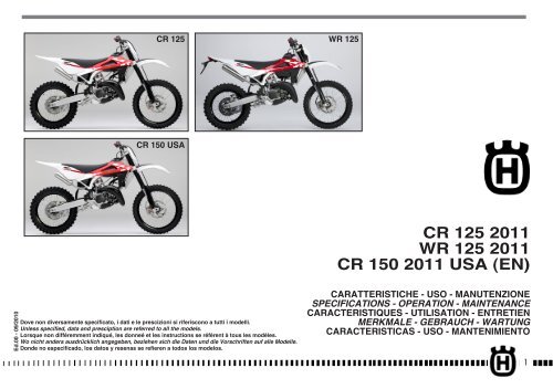
PRESENTATIONWelcome to the <strong>Husqvarna</strong> motorcycling Family!Your new <strong>Husqvarna</strong> motorcycle is designed and manufacturedto be the finest in its field.The instructions in this book have been prepared to providea simple and understandable guide for your motorcycle’soperation and care.Follow the instructions carefully to obtain maximum performanceand your personal motorcycling pleasure. Yourowner’s manual contains instructions for owner care andmaintenance.The main work of repair or maintenance requires the attentionof a skilled mechanic and the use of special toolsand equipment.Your <strong>Husqvarna</strong> dealer has the facilities, experience and originalparts necessary to properly render this valuable service.This “Owner’s <strong>Manual</strong>” is part and parcelof the motorcycle, hence, this had toremain with the motorcycle even whensold to another user.This motorcycle uses components designed thanks to systemsand state of the art technologies which are thereaftertested in competition.In competition motorcycles, every detail is verified after eachrace in order to always guarantee better performance. Forcorrect functioning of the vehicle, it is necessary to follow themaintenance and control table found on Appendix A.IMPORTANT NOTICES1) The <strong>CR</strong> models are guaranteed COMPE-TITION motorcycles exempt from functionaldefects, the suggested maintenance table forcompetition use is shown on Appendix A.2) <strong>WR</strong> vehicles are STREET LEGAL motorcycles(with LIMITED POWER ENGINE); they areguaranteed exempt from functional defectsand covered with legal guarantee, if theSTANDARD CONFIGURATION is maintainedand the suggested maintenance table, shownon Appendix A (page A8) is observed.If <strong>WR</strong> vehicles are transformed in COMPETI-TION MOTORCYCLES (with FULL POWER EN-GINE), the suggested maintenance table forcompetition use is shown on Appendix A.MOTO<strong>CR</strong>OSSENDURO2
IMPORTANTThe reference for recognition of the guarantee will be the MO-TORCYCLE CONFIGURATION, as shown below:A) STANDARD MOTORCYCLE, STREET LEGAL: with LIMITEDPOWER ENGINEB) COMPETITION MOTORCYCLE, RACING USE: with FULL POWERENGINEThis motorcycles was not designed for longtrips with the engine always at maximumrpm as can occur whilst travelling on roadsor highways. Long trips at full throttle cancause severe damage to the engine.This motorcycles is setup for competition useand therefore guarantees maximum performancewith the rider alone. It is therebynot recommended to use the vehicle on circuitsor off-road with a passenger.ALWAYS keep in mind that these motorcycles have been designedstrictly for competition use, that is, for conditions ofusage very different from those presented on the road.ALWAYS keep in mind that these motorcycleshave been designed strictly for competitionuse, that is, for conditions of usage very differentfrom those presented on the road.In order to maintain the vehicle’s “Guaranteeof Functionality”, the client must followthe maintenance program indicated in theuser’s manual by carrying out maintenancechecks at authorized HUSQVARNA dealers.The cost for substituting parts and for thelabour necessary in order to respect themaintenance plan, is charged to the client.NOTE: the guarantee is EXTINGUISHED in thecase where the motorcycle is rented.Important NoticeRead this manual carefully and pay special attention to statementspreceeded by the following words:Warning*: Indicates a possibility of severepersonal injury or loss of life if instructionsare not followed.Caution*: Indicates a possibility of personalinjury or equipment damage if instructionsare not followed.Note*: Gives helpful information.Parts ReplacementWhen parts replacement is required, use only <strong>Husqvarna</strong> ORIGI-NAL parts.Warning*: After an upset, inspect the motorcyclecarefully. Make sure that the throttle,brake, clutch and all other systems are undamaged.Riding with a damaged motorcyclecan lead to a serious crash.Warning*: Never attempt to start or operateyour motorcycle unless you are wearing appropriateprotective clothing. Always wear amotorcycle helmet, motorcycle boots, gloves,goggles and other appropriate protectiveclothing.Warning*: This motorcycle is a state of theart competition bike. Do not attempt to startor ride this motorcycle until you have receivedexpert instruction and are in excellentphysical condition.PRECAUTIONS FOR CHILDRENWARNING• Park the vehicle where it is unlikely tobe bumped into or damaged. Even slight orinvoluntary bumps can cause the vehicle totopple over, with subsequent risk of seriousharm to people or children.• To prevent the vehicle from tipping over,never park it on soft or uneven ground, noron asphalt strongly heated by the sun.•Engine and exhaust pipes become very hotduring riding. Always park your motorcyclewhere people or children can not easilyreach these parts, in order to avoid seriousburns.EN3
TABLE OF CONTENTSPagePRESENTATION........................................................................ 2IMPORTANT NOTICES............................................................... 2IDENTIFICATION DATA............................................................. 5TECHNICAL DATA..................................................................... 7LUBRICATION TABLE, SUPPLIES................................................ 8CONTROLS.............................................................................. 9RIDING................................................................................. 16IGNITION SYSTEM/ELETTRICAL SYSTEM............................. 44-46APPENDIX............................................................................. 47PRE-DELIVERY INSPECTION.................................................... 50ALPHABETICAL INDEX............................................................ 51PERIODIC MAINTENANCE -ADJUSTMENT.................... Appendix ANote•References to the “left” or “right” of the motorcycle are inthe sense of a person facing forwards.•Z: number of teeth• A: AustriaAUS: AustraliaB: BelgiumBR: BrazilCDN: CanadaCH: SwitzerlandD: GermanyE: SpainF: FranceFIN: FinlandGB: Great BritainI: ItalyJ: JapanUSA: United States of America•Where not specified, all the data and the instructions arereferred to any and all Countries.4
IDENTIFICATION DATAThe engine number is printed on the upper side of the enginecase, whereas the frame number is printed on the steering tube.Always state the number stamped on the frame(and write it on this booklet), when placing orders for spareparts, or when asking for informations about your motorcicle.1ENFRAME NUMBERVEHICLE IDENTIFICATION NUMBER (V.I.N.)The full 17-digit serial, or Vehicle Identification Number, isstamped on the steering tube (R.H. side).<strong>CR</strong> <strong>150</strong> USA/CDN2(l) = Model designation(▲) = Model Year (<strong>2011</strong>)(♦) = Progressive no.2ZKH <strong>CR</strong>153# BV 000001(l) (▲) (♦)<strong>CR</strong> <strong>125</strong><strong>WR</strong> <strong>125</strong>1ZKH 4H00AA BV 050001(l) (▲) (♦)3ZKH 4H00AA BV 000001(l) (▲) (♦)1. Frame serial number2. Engine serial number5
control location1. Front brake lever2. Throttle grip3- L.H. commutator (<strong>WR</strong>)4. Rear brake control pedal5. Starting pedal6. Clutch control lever7. Fuel tank filler cap8. Gearbox control pedal9. Choke (L.H. side)10. Fuel cock11. Air bleeding screw on front fork leg12. Compression damper adjustment (front fork leg)13. Extension damper adjustment (front fork leg)14 .Rear shock absorber spring preload adjustment15. Rear shock absorber compression damper adjustment (low and high damping speeds)16. Rear shock absorber extension damper adjustment6
TECHNICAL DATAENGINEType..............................................single cylinder, 2 strokeCooling........................................................................liquidBore (<strong>CR</strong>/<strong>WR</strong> <strong>125</strong>)......................................................2.13 in.Bore (<strong>CR</strong> <strong>150</strong>).............................................................2.28 in.Stroke........................................................................2.15 in.Displacement (<strong>CR</strong>/<strong>WR</strong> <strong>125</strong>)............................... 7.62 cu. in.Displacement (<strong>CR</strong> <strong>150</strong>)...................................... 8.79 cu. in.Compression ratio(with closed ports) (<strong>CR</strong>/<strong>WR</strong> <strong>125</strong>).....................................8,8:1(with closed ports) (<strong>CR</strong> <strong>150</strong>)............................................8,6:1Starting ................................................................. kick startTIMING SYSTEMType..........lamellar valve on suction in the crankcase andH.T.S. valve with mechanical control on the exhaustLUBRICATIONEngine . . . . . . . . . . . . . . . . . . . . 4% (1:25) of oil-gasoline mixduring running in; NOT LESS than 3% (1:33)when running in isoverPrimary drive transmission/Gearbox . .by the oil contained inthe crankcaseIGNITIONType...... . . . . . . . . . . . . . . . . . . . . . . . . . . . . electronic digitalcapacitor-discharge type, with variable advanceSpark plug type . . . . . . . . . . . CHAMPION QN B4/NGK BR9EGGap . . . . . . . . . . . . . . . . . . . . . . . . . . . . . . . . . . . .0.0236 in.FUEL SYSTEMType.......................................... Carburettor “Mikuni” TMX 38Venturi diameter............................................................1.5 in.High speed jet (<strong>CR</strong>)............................................................460High speed jet (<strong>WR</strong>)...........................................................380Low speed jet (<strong>CR</strong>)...............................................................35Low speed jet (<strong>WR</strong>)..............................................................15Starting jet (<strong>CR</strong>)...................................................................80Starting jet (<strong>WR</strong>)..................................................................50Main nozzle..............................................................R-8 (914)Floater (n° 2)..................................................................g 6,1Throttle piston (<strong>CR</strong>).............................................................4,0Throttle piston (<strong>WR</strong>)............................................................5,0Metering pin................................................................ 6BFY43Metering pin slot (<strong>CR</strong>)........................................................ 3rdMetering pin slot (<strong>WR</strong>).......................................................2ndIdle mixture adjusting screw (<strong>CR</strong>)...................... rounds 1+1/4Idle mixture adjusting screw(<strong>WR</strong>)...................... rounds 1+1/2PRIMARY DRIVEDrive pinion gear- Clutch ring gear .......................... Z 22- Z 71Transmission ratio .........................................................3,227CLUTCHType......oil bath multiple disc clutch, mechanical controlTRANSMISSIONType........................................ constant mesh gear typeTransmission ratio1st gear . . . . . . . . . . . . . . . . . . . . . . . . . . . .2,357 (z 33/14)2nd gear ............................1,866 (z 28/15)3rd gear ............................1,579 (Z 30/19)4th gear . . . . . . . . . . . . . . . . . . . . . . . . . . . .1,350 (Z 24/22)5th gear . . . . . . . . . . . . . . . . . . . . . . . . . . . .1,181 (Z 26/22)6th gear . . . . . . . . . . . . . . . . . . . . . . . . . . . .1,000 (Z 21/21)SECONDARY DRIVETransmission sprocket- Rear wheel sprocket ............ Z 13- Z 50Transmission ratio..........................................................3,846FINAL RATIOS1st gear .......................................................................29,2582nd gear......................................................................23,1703rd gear ......................................................................19,5994th gear.......................................................................16,7575th gear ......................................................................14,6696th gear ......................................................................12,412FRAMEType............................... Steel single tube cradle (roud tubes);light alloy rear frame.FRONT SUSPENSIONType...................”Upside-down” telescopic hydraulic front forkwith advanced axle (adjustable in compression and reboundstroke); stanchions tubes Ø 1.89 in.Legs axis stroke........................................................11.8 in.REAR SUSPENSIONType..............progressive with hydraulic single shock absorberWheel stroke.............................................................11.6 in.FRONT BRAKEType.fixed disc Ø 10.24 in. “Wave” type with hydraulic controland floating caliperREAR BRAKEType................................floating disc, Ø 9.45 in. “Wave” typewith hydraulic control and floating caliperRIMSFront.....................................................in light alloy: 1,6x21”Rear (<strong>CR</strong>) . . . . . . . . . . . . . . . . . . . . . . in light alloy: 2,15x19”Rear (<strong>WR</strong>-<strong>CR</strong> <strong>150</strong>) ................in light alloy: 2,15x18”EN7
TYRESFront (<strong>CR</strong>) ..............................80/100x21”Front (<strong>WR</strong>-<strong>CR</strong> <strong>150</strong>) . . . . . . . . . . . . . . . . . . . . . . . .90/90x21”Rear (<strong>CR</strong>) . . . . . . . . . . . . . . . . . . . . . . . . . . . . . 100/90x19”Rear (<strong>WR</strong>-<strong>CR</strong> <strong>150</strong>) ....................... 120/90x18”Cold tire pressure(front) (*). . . . . . . . . . . . . . . . . . . . . . . . . . . . . 12.8÷14.2 psi( front) (%) ................................ 15.6 psirider and passenger(rear) (*) . . . . . . . . . . . . . . . . . . . . . . . . . . . . . 11.4÷12.8 psi(rear) (%) ................................. 14.2 psi(*) Racing use - (%) Road useDIMENSION, WEIGHT, CAPACITYWheelbase (<strong>CR</strong>) ........................................................57.48 in.Wheelbase (<strong>WR</strong>-<strong>CR</strong> <strong>150</strong>) ...........................................57.68 in.Overall length(<strong>CR</strong>).......................................................87.2 in.Overall length (<strong>WR</strong>-<strong>CR</strong> <strong>150</strong>).......................................88.98 in.Overall width (<strong>CR</strong>).....................................................32.28 in.Overall width (<strong>WR</strong>-<strong>CR</strong> <strong>150</strong>)........................................33.07 in.Overall height (<strong>CR</strong>) ...................................................51.38 in.Overall height (<strong>WR</strong>-<strong>CR</strong> <strong>150</strong>) ......................................51.18 in.Saddle height (<strong>CR</strong>)....................................................38.78 in.Saddle height (<strong>WR</strong>-<strong>CR</strong> <strong>150</strong>)........................................38.38 in.Minimum ground clearance (<strong>CR</strong>)................................12.79 in.Minimum ground clearance (<strong>WR</strong>-<strong>CR</strong> <strong>150</strong>).....................12.4 in.Kerb weight, without fuel(<strong>CR</strong>) . . . . . . . . . . . . . . . . . . 202.8 lbKerb weight, without fuel(<strong>WR</strong>) ..................211.6 lbKerb weight, without fuel(<strong>CR</strong><strong>150</strong>) . . . . . . . . . . . . . . . 206.8 lbFuel tank capacity, (1.32 Imp. quarts, 1.59 U.S. quart reserveincluded) .................................. 1.54 Imp. gall., 1.85 U.S. gall.Coolant capacity.................................0.97÷1.14 Imp. Quarts ,.............................................................1.16÷1.37 U.S. QuartsTransmission oil . . . . . . . .0.70 Imp. Quarts , 0.85 U.S. QuartsTABLE FOR LUBRICATION, SUPPLIESEngine lubricating oilCASTROL A747Gearbox and primary drive lubricating oilCASTROL POWER 1 RACING 10W-40Engine coolantCASTROL MOTORCYCLE COOLANTBrake system fluidCASTROL RESPONSE SUPER DOT 4Grease lubricationCASTROL LM GREASE 2Final drive chain lubricationCASTROL CHAIN LUBE RACINGFront fork oilKHL15-11Oil for rear shock absorberCASTROL SYNTHETIC FORK OIL 5WElectric contact protectionCASTROL METAL PARTS CLEANERFillers for radiatorAREXONS TURAFALLE LIQUIDO8
FUEL COCKCONTROLSThe cock (1) set on left side of tank has three positions:OFF - closed; no fuel outlet;ON - open; fuel outflows from the main flow;RES - reserve; fuel outflows from the reserve flow.When running, should feed problem ensue, set cock lever on RESposition. After filling up, take the cock in ON position again.WARNING*: Be careful not to touch the hotengine while operating the fuel valve.A fuel filter is incorporated in the fuel valves. Accumulation ofdirt in the filter will restrict the flow of the fuel to the carburetor.Therefore, the fuel filter should be serviced periodically.To service:1- Drain the fuel from the fuel tank. Disconnect the fuel line.2- Remove the fuel valve by removing the screws. Wash the fuelscreen filter in cleaning solvent.3- Reassemble the fuel valve in the reverse order of removal.Turn the fuel valve “ON” and check for leaks.SIDESTANDA sidestand (1) is supplied with every motorcycle.WARNING*: The stand is designed to supportthe weight of the MOTORCYCLE ONLY. Donot sit on the motorcycle using the stand forsupport as this could cause structural failureto the stand and could cause serious bodilyinjury.<strong>WR</strong>: Periodically check the side stand (see “Periodical maintenancecard”); check that the springs are not damaged and thatthe side stand freely moves. If the side stand is noisy, lubricatethe fastening pivot (A).EN1. Fuel cockA. To carburettor9
FUELThe motorcycle is equipped with 2 stroke engine that requiresa gasoline-oil mixture. Recommended fuel: premium grade unleadedfuel (R.O.N. 98).Note*: Do not continue operation if the enginepings or knocks. The engine will bedamaged and could seize.CARBURETOR CHOKEThe starter knob (1), located on the left side of the carburetor, isused to enrich the mixture during the engine start.Pull out the knob to open the starter, and pull the lever upwardsto close it.WARNING*: If “knocking” or “pinging”occurs, try a different brand of gasoline orhigher octane grade.WARNING*: Gasoline is extremely flammableand can be explosive under certain conditions.Always stop the engine and do notsmoke or allow flames or sparks in the areawhere the motorcycle is refueled or gasolineis stored.WARNING*: Do not overfill the tank. After refueling,make sure the tank cap (2) is closedsecurely.210
DIGITAL INSTRUMENT, WARNING LIGHTS (<strong>WR</strong>)- The instrument functions are the following, as shown below.1- SPEED (Km/h or mph) / ODO (figure 1)The motorcycle is equipped with a digital instrument; on theinstrument are located 2 warning lights too: high beam andblinkers.1- BLUE warning light “HIGH BEAM”2- GREEN warning light “BLINKERS”The instrument display illuminates (amber colour) when theengine started.NOTES- Every time the engine starts, for the first 2 seconds, theinstrument shows the version of the checking SW; after thecheck, the instrument shows the last planned function.- When the motorcycle engine is OFF, the instrument doesn’talso show its functions.- To select the instrument functions and to set to zero thefunctions, use the S<strong>CR</strong>OLL knob (A).1- SPEED / ODO (figure 1)2- SPEED / CLOCK (figure 2)3- SPEED / TRIP (figure 3)4- SPEED / CHRONO (figure 4)1- SPEED / ODO (figure 1).................- SPEED: motorcycle speed- maximum value: 299 Km/h or 299mph;- ODO: odometer- maximum value: 99999 km;To replace kilometers with miles or miles with kilometers proceedas follows:1) set to figure 1, stop the engine and push the knob S<strong>CR</strong>OLL(A);2) Start the engine holding pushed the button S<strong>CR</strong>OLL (A) untilthe symbol “Km/h” will be displayed;3) then the symbols “Km/h” and “Mph Miles” will be displayedalternatively. Push again the S<strong>CR</strong>OLL (A) button when theunit you wish to use is displayed.EN11
THROTTLE CONTROLThe throttle knob (1), is located on the right hand side of thehandlebar. The position of the throttle control can be adjustedby loosening the two fastenig screws .CAUTIONDo not forget to tighten the screws (A) afterthe adjustment.STEERING LOCK (<strong>WR</strong>)The motorcycle is equipped with a steering lock (1) on the R.H.side of the steering head tube.To lock it, procede as follows: turn the handlebar leftwards,place the key in lock and turn counterclockwise. Push the keyinwards (if necessary, turn to and from). Turn the key clockwiseand remove it from the lock.To unlock the steering lock, reverse the above procedure.ENFRONT BRAKE CONTROLThe brake control lever (2) is located on the right hand side ofthe handlebar. The position of the throttle control can be adjustedby loosening the two fastenig screws .CAUTIONDo not forget to tighten the screws (B) afterthe adjustment.113
HANDLEBAR COMMUTATOR (<strong>WR</strong>)The left commutator has the following controls:1) Engine stop button ( )2) HI = ( ) Selection control High beamLO = ( ) Selection control of Low beam3) TURN= Activation of left turn indicators (self cancelling)= Activation of right turn indicators (self cancelling)To deactivate the indicator, press the control lever afterits returning to center.4) HORN = ( ) Warning horn5) LIGHTS= Lighting control of lowbeams and high beam.= Lighting control of position lights.= OffENGINE STOP BUTTON (<strong>CR</strong>)On the left side of the handlebar, near the clutch control, is locatedthe engine stop button (1).CLUTCH CONTROLThe clutch lever is located on the left-hand side of the handlebarand is protected against dirt filtering in. The lever support isprovided with adjusting screw (1) to regulate clutch wire freeplay. The clutchlever can be adjusted to suit your driving position.1CAUTIONDo not forget to tighten the screws (C) afterthe adjustment.A: To decrease clearanceB: To increase clearanceREAR BRAKE CONTROLThe rear brake control (1) is placed on the right-hand side ofthe motorcycle. On models <strong>WR</strong> a stop switch, during the brakingaction, causes the rear light to come on.114
GEAR SHIFT CONTROLThe lever (1) is placed on the left-hand side of the engine. Theoperator must release the lever after each gear change to allowit to return to its central position before another gear changecan be made.Neutral position (N) is between first (low) and second gears.First gear is engaged by pushing the lever downwards; all theother gears are engaged, by pushing the lever upwards.The position of the gear shift lever on the shaft can be varied by:loosening screw; pulling lever out; placing lever in new positionon the shaft when the operation is over tighten the screw andthen tightening the screw.CAUTION*: Do not shift gears without disengagingthe clutch and closing the throttle. Theengine could be damaged by “overspeed”and shock.WARNING*: Do not downshift when travelingat a speed that would force the engine tooverrev in the next lower gear, or cause therear wheel to lose traction.KICKSTART PEDALThe kickstart pedal (2) is situated on the right-hand side of themotorcycle.ENN: Neutral1215
RIDINGBEFORE EVERY RIDE MAKE FOLLOWING CHECKSWARNING!Before each ride, to prevent accidents or failures during ride,make sure to go through following list.1. Check all fluidsA. Transmission oil levelB. fuel levelC. coolant levelMake sure all caps are properly adjusted.WARNING*: Don’t remove radiator cap whenhot!2. Check all controlsA. Throttle handgripB. Clutch leverMake sure cables are not damaged and turn smoothly.3. Check brakesLook for brake fluid leaks and worn hoses. Check for properfunctioning.4. Check suspensionsCompress fork and rear suspensions. Look for oil leaks andensure proper functioning.5. Check wheelsCheck spokes and look for worn bearings.Check rims and tyres.Check tyre pressure.6. Check chain rollers and sprocketsCheck wear on chain rollers and sprocketsEnsure chain is correctly adjusted and lubricated.7. Check air filter and intake systemCheck that air filter is cleanCheck all rubber connections and clamps.8. Check exhaust systemCheck hook up, look for cracksCheck muffler.9. Check torqueA. Spark plug (see page 23).B. General check of torque10. Check steering actionCheck bearing play.11. Check the electric system (<strong>WR</strong>).Start the engine and check that the front and rear lamps, thestop light, the turn signals the cluster warning lights and thehorn are working correctly.WARNING*: Failure to perform these checksevery day before you ride may result in serousdamage or a severe accident.RUNNING INTo obtain the best settling of the engine moving elements, fordriving your motorcycle to the best of your capability, run in theengine for several hours, following these procedures:1. FROM STOP POSITION. Start the engine and run at idle, butopen the throttle periodically and briefly until the engine is thoroughlywarmed up. Within 3-4 minutes the coolant temperaturewill have reached approximately 60° C/140° F. (Do not ridethe motorcycle).2. Stop the engine, and let it cool down naturally until its temperatureis equal to the ambient air temperature. This will allowthe piston to align itself to any imperfections which might existat the cylinder wall.3. Repeat steps 1 and 2. (Do not ride the motorcycle).4. Bring the engine up to normal running temperature. Ride themotorcycle approximately 10 minutes at moderate speeds. Thenrepeat cool down procedure.AVOID HARD ACCELERATIONS.5. Bring engine up to normal temperature. Ride motorcycleapproximately 15 minutes at moderate to high speeds. Againavoid hard accelerations.6.Repeat cool down procedure.7. Full throttle operation must be avoided until the engine hasreached operating temperature, even after the break in processis completed. When the above procedure is followed correctly,engine durability and performance will be greatly enhanced.CHECKS WHILE RUNNING INWhen running in, the following should be checked out:- WHEELS SPOKES TENSION;- TIGHTENING OF WHEELS;- FORK PIN TIGHTENING;- CHAIN ADJUSTMENT;- STEERING BEARING PLAY;- HANDLEBAR TIGHTENING;- ENGINE GRIP TO FRAME;- SUCTION FITTING GRIP;- HEAD AND CYLINDER NUTS GRIP.Note*:After break in, install a new spark plug andchange the transmission oil.After running-in, check that vehicle nuts andbolts are properly tightened.16
ENGINE STARTFor the correct start of a cold engine proceed as follows:- shift the transmission into neutral;- set fuel valve (1) in ON position;- lift the knob lever (3) on the carburetor.Leaving the throttle in closed position operate kick-start (4).Take the knob lever in its initial position as soon as the engineis idling.When starting with an already warmed up engine DO NOT USEthe starter. You can start the engine with the gear inserted, afterdisconnecting of the clutch.If the carburetor is flooded, shut off the fuel supply and thestarter and operate the crank lever or the kick-start until theengine starts. If necessary, remove the spark plug and dry it.IMPORTANT NOTE IN CASE OF COLD STARTSAT LOW TEMPERATURESIt is recommended to briefly warm-upthe engine at idle until, after havingdisengaged the starter, there is a normalresponse from the engine whenopening the throttle.This will enable the lubricant to reachthe correct working temperature therebyguaranteeing a correct functioning ofall engine parts.Avoid overheating the engine.IMPORTANTNever accelerate the engine after a cold start.WARNING*: Exhaust contains poisonous carbonmonoxide gas. Never run the engine in aclosed garage or in a confined area.WARNING*: This high performance motorcyclecan some times «kick back» stronglywhen you are starting it.Do not attempt to start this motorcycle unlessyou are wearing high top heavy sided ridingboots. You could seriously hurt you legif the kickstarter kicked back and your footslipped.EN31417
STOPPING THE MOTORCYCLE AND THE ENGINE- Close the throttle (1) completely so that the engine will helpslow down the motorcycle.- For normal braking, gradually apply both front and rearbrakes while down shifting (for maximum deceleration, applythe front and rear brakes firmly).- When stopped, pull the clutch lever and shift gear lever (2) inneutral position.- Press the engine stop button (3).- Close the fuel cock (4).When the bike is off, place it on its side stand.1<strong>CR</strong>32<strong>WR</strong>3418
TRANSMISSION OIL LEVEL CHECKINGA. Transmission oil levelKeeping the motorbike level and in a vertical position, checkthe oil level through the inspection (1) window on the rightcrankcase. Check if level (a) is about midway of the inspectionporthole.To fill up, remove the filler cap (2).Note*: Have this operation made with warmed-upengine.WARNING*: Be careful not to touch hotengine oilTRANSMISSION OIL CHANGETo completely replace the oil, unscrew the plug (A) under theoil sump and let oil come out, then screw the plug again with itsgasket and pour fresh oil from the hole of the loading plug.Use only the prescribed quantity and type of oil (see on page8)Note:Have this operation made with warmed-upengine.A: Draining plugCOOLANT LEVEL CHECKCheck level (1) in right-hand radiator when engine is cold (placethe motorcycle so that it is perpendicular to the ground). Thecoolant should be approximately 10 mm above cells.The radiator cap is provided of two unlocking positions, thefirst being for the previous pressure discharge in the coolingsystem.WARNINGAvoid removing radiator cap when engineis hot, as coolant may spout out and causescalding.ENNOTEDifficulties may arise in eliminating coolantfrom varnished surfaces. If this occurs, washoff with water.119
REPLACEMENT OF COOLING FLUIDThe cooling liquid replacement must be performed with coldmotor, as follows:- remove the R.H. radiator plug;- remove the drain screw (2) on the pump cover or the pumpcover by loosening the three screws (1);- slope the motorbike on the right, to make the liquid come outeasily;- let the liquid drain completely;- reassemble the drain screw or the pump cover;- pour the necessary quantity of liquid in the radiator (page 8);- warm up the motor in order to eliminate any possible air bubble;- fit the motor in vertical position and check that the liquid inthe radiators must be 10 mm/0.4 in. over the radiant mas (ifnot, top it up);- screw the R.H. radiator plug.WARNING*: Coolant on tires will make themslippery and can cause an accident or injury.Periodically check the connecting hoses (see “Periodical maintenancecard”): this will avoid coolant leakages and consequentengine seizure: If hoses show cracks, swelling or hardenings dueto sheats desiccation, theirreplacement shall be advisable. Check the correct tightening ofthe clamps.20
THROTTLE CABLE ADJUSTMENTThe throttle cable can be adjusted using the screw set on thethrottle, or using the adjusting screw set on thecarburettor cover. To check for proper adjustment of throttlecable, proceed as follows:- remove rubber cap;- move transmission sheath to and fro to ensure a play of approx.1 mm;- should play be greater than 1 mm, loosen lock nut (1) andregister (2); should play less than 1 mm, then tighten locknut and register;- if register (2) should not provide sufficient movement toallow for correct adjustment, then adjust register placed oncarburetor.There should be approx. 1 mm play on latter register; shouldthis not be the case, then loosen lock nut (3), and loosen ortighten screw (4), to respectively increase or decrease theplay.WARNING*: Operation with damaged throttlecable could result in an unsafe ridingcondition.IDLING ADJUSTMENTIdling should be adjusted only when the engine is hot and throttleis closed, as follows:- turn idle adjusting screw (1) so as to increase rpm (turnclockwise to increase rpms, counterclockwise to decrease rpm);- turn fuel mixture adjusting screw (2) clockwise or anticlockwiseuntil engine runs smoothly;- gradually loosen screw (1) to ensure that engine runs properly.WARNING*: Exhaust gas contains poisonouscarbon monoxide gas. Never run the enginein a closed area or in a confined area.EN21
CLUTCH ADJUSTMENTThe clutch is adjusted by stretching the cable using the adjustingunit positioned on the handlebar.As a rule it is sufficient to operate on the handlebar register torestore the clearance due to the flexible transmission stretch.The control lever must always have an empty stroke (C)(3 mm) before starting clutch disengagement. To adjust thisclearance, act on register (2) after taking out rubber cap (1);turn the register in the direction indicated by arrow A to reducethe clearance (C); turn it in the direction indicated by arrow B toincrease the clearance.The adjustment can be also effected with tightener (1) set onthe right of the frame. Take care to tighten properly the locknut. If the clutch slips under load or drags in disengaged positionafter play has beenadjusted, it must be taken apart for inspection. For this operationapply to a Dealer.1. Rubber cap2.Adjusting screw1. Adjusting screw2. Locknut3. Rubber cap22
SPARK CONTROLUse NGK BR9EG or CHAMPION QN84; spark plug (2); the gapis 0,6 in.A wider gap may cause difficulties in starting engine and inoverloading coil.A gap that is too narrow may cause difficulties when accelerating,when idling the engine or when performing at lowspeeds.Clean the dirt away from the base of the spark plug before removingit from the cylinder after removing the cap (1).It is very useful to examine the state of the spark plug just after ithas been removed from the engine since the deposits on the plugand the colour of the insulator provide useful indications.Correct heat rating:The tip of the insulator should be dry and the colour should be lightbrown or grey.High heat rating:In this case, the insulator tip is dry and covered with dark deposits.Low heat rating:In this case, the spark plug is overheated and insulator tip is vitreous,white or grey in colour.CAUTION*: Select a spark plug with a colder orhotter heat range carefully and cautiously. Aspark plug with too hot a heat range may leadto preignition and possible engine damage. Aspark plug with too cold a heat range may foulas the result of too much carbon buildup.Before refitting the plug, thoroughly clean theelectrodes and the insulator using a brass-metalbrush.Apply a little graphite grease to the spark plugthread; fit and screw the spark plug by handthen tighten to the torque of 23,5÷25,5 Nm-17,3÷18,8 ft/lb.Spark plugs which have cracked insulators orcorroded electrodes should be replaced.ENVOLTAGE REGULATOR (<strong>WR</strong>)Voltage regulator (1) is secured onto a special plate positionedunder fuel tank.1223
AIR FILTER CHECKTurn rear pin (1) counterclockwise, remove the saddle from thefront afstening screw.Remove screw (3) and the filter (4). Separate filter (5) fromframe (6).AIR FILTER AND CLEANINGWash the filter with a specific detergent (CASTROL FOAM AIRFILTER CLEANER or similar) then dry it fully (wash filter withgasoline only in case of necessity).Plunge the filter in special oil for filters (CASTROL FOAM AIRFILTER OIL or similar) then wring it to drain superfluous oil.CAUTION*: Do not use gasoline or a low flashpointsolvent to clean the element. A fire orexplosion could result.CAUTION*: Clean the element in a well ventilatedarea, and do not allow sparks orflames anywhere near the working area.ASSEMBLYTo ensure tight fit, slightly (C) grease filter edge on side facingfilter housing.While re-inserting the filter into its housing, make surs thatpiece (A) is turned upwards and edge (B) is on the left lowerside of the filter case. Reassemble the parts previously removed(battery: connect the positive cable first).CAUTION*: If the element assembly is notinstalled correctly, dirt and dust may enterand the engine resulting in rapid wear of thepiston rings and cylinder.146A35CB24
STEERING WHEEL BALL PLAY ADJUSTMENTTo ensure maximum safety, the steering wheel should alwaysbe regulated so that the handlebars steering the motorcyclerotate freely without play. To check steering wheel adjustment,place kick stand or other support under the engine so that thefront wheel is raised from ground.Place slight pressure on the tips of the handlebars to rotate steeringwheel; the handlebars should also rotate without effort.Stand in front of the motorcycle and grasp the lower end ofthe fork rods sliders moving them in the direction of their axis.Se si avverte gioco occorrerà eseguire la regolazione operandocome segue:- loosen steering sleeve nut (1).- Loosen four screws that fix steering head to fork rods (3).Turn the steering ring nut (2) clockwise of the steering sleeveproper tool, to adjust play properly.- Tighten steering sleeve nut (1) to a torque setting of 57,9÷65,1Lb/ft; (78,4÷88,3 Nm).- Tighten four screws on the steering head (3) to a torque of22,5÷26,5 Nm (16.6÷19.5 Lb/ft).ENCAUTION*: Do not ride a motorcycle withdamaged steering stem bearings. An unsafehandling condition can result.3 1225
ADJUSTMENT OF THE CONTROL LEVER ANDCHECK OF THE FRONT BRAKE FLUID LEVELThe adjuster (2), located on the control lever, allows adjustingof the free play (a).Free play (a) must be at least 3 mm (0.1 in.).The level of the fluid in pump reservoir must never be belowthe minimum value (1), which can be checked from the windowon the rear side of the pump body.A decrease of the fuel level will let air into the sustem, hencean extension of the level stroke.WARNING*: If the brake lever feels mushywhen it is applied, there may be air inthe brake lines or the brake may bedefective. Since it is dangerous to operatethe motorcycle under such conditions, havethe brake checked immediately by anauthorized HUSQVARNA dealer.CAUTION*: Do not spill brake fluid on to anypainted surface or lenses.CAUTION*:Do not mix two brands of fluid.Change the brake fluid in the brake line ifyou wish to switch to another fluid brand.CAUTION*: Brake fluid may cause irritation.Avoid contact with skin or eyes. In case ofcontact, flush thoroughly with water and calla doctor if your eyes were exposed.A: to encrease clearanceB: to decrease clearance1+A2B-26
REAR BRAKE PEDAL POSITION ADJUSTMENTRear brake idle stroke adjustmentCHECKING THE FLUID LEVELThe position of the rear foot brake pedal as to the footrest maybe adjusted according to the individual needs. For the adjustingproceed as follows:- loosen the screw (1);- turn the cam (2) in order to adjust the brake pedal idle stroke(A);- the operation done, tighten the screw (1).The rear brake foot pedal should have a (B) 5 mm (0.2 in.) idlestroke before starting the true braking action.Should this not happen, operate as follows:- loosen nut (3);- operate the pump rod (4) to increase or decrease the idle stroke;- tighten nut (3) at the end of the operation.The level (A) must be set between the pump tank notches.ENThe adjusting operation carried out, adjust the idle stroke of thepedal as follows..WARNINGWhen the idle stroke figures are not met, thebrake pads will be subjected to a fast wearthat may bring to the TOTAL BRAKE INEFFEC-TIVENESS.2134A27
ADJUSTING THE SUSPENSIONS ACCORDING TOPARTICULAR TRACK CONDITIONSThe following information is a useful guide for setting up thesuspensions according to the road conditions.Always start from the standard calibration before making anychange on the suspensions. Afterwards, increase or decrease theadjusting clicks one at a time.SANDY GROUNDFork: have a harder compression adjustment, or replace thestandard spring with a harder one, and make a softer compressionadjustment and a harder extension adjustment at the sametime.Shock absorber: have a harder compression, and expecially aharder extension adjustment. Work on the spring preload tolower the motorcycle rear side.NOTE:When the fork results as either too soft or too hard for any adjustmentconditions, check the oil level inside the forkrod.The level can either be too low or too high. Remember that toomuch oil inside the fork will involve a more frequent air drainage.When the suspensions do not react to the changes of calibration,check that the adjusting units are not blocked.HARD GROUNDFork: softer compression adjustment.Shock absorber: softer compression adjustment.The softer adjustment for the two suspensions is also used bothin compression and in extension when driving at top speed, inorder to have better grip of the tires.MUDDY GROUNDFork: have a harder compression adjustment, or replace thestandard spring with a harder one.Shock absorber: have a harder compression and extension adjustments,or replace the standard spring with a harder one.Work on the spring preload to lift the motorcycle rear side.We advise replacing the springs of both suspensions to compensatethe weight increase due to the piling of the mud.28
The standard calibrations and the adjustment procedures areshown below.ADJUSTING THE COMPRESSION FORKa) COMPRESSION (<strong>CR</strong>: UPPER REGISTER; <strong>WR</strong>: LOWER REGISTER)Standard calibration: -9 clicks (<strong>CR</strong>)Standard calibration: -10 clicks (<strong>WR</strong>)Remove plug (B) and turn register (A) clockwise until the positionof fully closed is reached then, turn back by the mentionedclicks.To obtain a smoother braking action, turn the registeranticlockwise. Reverse the operation in order to obtain a harderaction.b) EXTENSION (<strong>CR</strong>: LOWER REGISTER; <strong>WR</strong>: UPPER REGISTER)Standard calibration: -13 clicks (<strong>CR</strong>)Standard calibration: -10 clicks (<strong>WR</strong>)To reset standard calibration turn register (C) clockwise to reachthe position of fully closed; then, turn back by the mentionedclicks. To obtain a smoother braking action, turn the registeranticlockwise. Reverse the operation in order to obtain a harderaction.c) AIR VENT (to carry out after each competition, or monthly).Set the motorcycle on a central stand and release the fork fullyand loosen the air vent valve (D). Once this operation is over,tighten the valve.- <strong>WR</strong>:WARNING: Never force the adjusting screwsbeyond the maximum opening and closurepositions.OIL FORK LEVELFor the regular fork operation, both legs must be provided withthe necessary oil quantity.OIL QUANTITY IN EACH FORK LEG- <strong>CR</strong>: 352 cm 3b)<strong>CR</strong>emove the fork legs from the fork to check the oil level. Workas follows:- remove the damper rod caps;- remove springs from the legs letting the oil drain into thelegs;- bring fork to stroke end;- check that level is at the distance (A) of 140 mm (5,51 in.)from rod upper limit.NOTEAlways replace both the spring and the spacers to keep thepreload value unchanged.a) A a)b) C <strong>CR</strong>DAD<strong>WR</strong><strong>WR</strong>AEN<strong>WR</strong><strong>CR</strong>29
HANDLEBAR POSITION AND HEIGHT CHANGEThe handlebar position (a) and height (b) can be changed forbetter suiting Your driving requirements. To effect these operations,remove the upper clamp (1) and the lower one (2), afterremoving the fixing srews (3) and (4).a) Handlebar position changeTurn the lower clamp (2) 180° to move forward or backward(10mm- 0.04in.) the handlebar position with respect to theoriginal setup.b) Handlebar height changeRemove the lower spacer (A) then replace the screw (4) with anew one of L=65 mm (2.56 in.) height.Once these operations are completed, tighten the screws (3) to2,75-3,05 kgm (27-30 Nm; 19.9-22 Lb/fts) and the screws (4)to 2,0-2,2 kgm (19,6-21,6 Nm; 14.5-15.9 Lb/fts4132A1A2330
ADJUSTING THE SHOCK ABSORBERThe rear shock absorber must be adjusted according to the riderweight and track conditions.Proceed as follows:1. With motorcycle on the stand, measure distance (A).2. Take the normal riding position on the motorcycle with allyour riding apparel.3. With somebody’s help, take the new distance (A).B: axis of the panel screwC: axis of rear wheel pin4. The difference between these two measurements constitutesthe “SAG” of the motorcycle’s rear end.Suggested SAG: 4 in. with cold shock absorber. 3.7 in. withwarmed up shock absorber.5. To get the right SAG according to your weight, adjust theshock absorber spring preload as described at side.WARNING*: Never disassemble shock absorber,which contains highly compressednitrogen. Contact your Dealer for such majorservice. Do not incinerate.ADJUSTING THE SHOCK ABSORBER SPRINGPRELOADProceed as follows:1. First turn counterclockwise fastening rear pin (1) then removesaddle, screws (2) and R.H. side panel (3).ENBA23C31
2. Clean ringnut (1) and adjusting nut (2) of the spring (3).3. Either with a hook wrench or an aluminium punch, loosenthe ringnut .4. Turn the adjusting nut as required.5. When the adjusting operation is over (according to yourweight and riding style), tighten the ringnut. (Torque forboth ringnuts: 5 Kgm; 49 Nm; 36.2 ft/lb).6. Reassemble R.H. side panel and saddle.WARNING*:Be careful not to touch hot exhaustpipe while adjusting the shock abosrber.SHOCK ABSORBER DAMPING ADJUSTMENTAdjustment of the compression stroke is independent from therebound stroke.A) COMPRESSION - Standard calibration:1) Low damping speed:- 15 clicks (± 2 clicks)(register 4)2) High damping speed:- 15 clicks (± 2 clicks)(register 6)To reset the standard calibration, turn upper registers (4) and(6) clockwise until reaching fully closed position.Return then back for the mentioned clicks. In order to obtain asmooth braking action, turn the registers anticlockwise. Reversethe operation in order to obtain a harder braking action.B) EXTENSION - Standard calibration:- 18 clicks (± 2 clicks)To reset the standard calibration, turn lower register (5) clockwiseuntil reaching fully closed position. Return then back forthe mentioned clicks. In order to obtain a smooth brakingaction, turn the register anticlockwise. Reverse the operationin order to obtain a harder braking action132532
CHAIN ADJUSTMENT (Fig. A)Fast adjustment (Fig. B.)Chain should be checked, adjusted and lubricated as per theMaintenance Chart to ensure security and prevent excessivewear. If the chains becomes badly worn or is poorly adjusted(i.e., if it is too loose or too taught), it could escape from sprocketor break.To adjust the rear chain it is necessary to lower the rear part ofmotorcycle so to line up the drive sprocket axle, the rear swingarm axle and the rear wheel axle as shown on drawing. Thanlet turn three times the rear wheel. Now the chain should notbe tight.Push the chain towards the final part of runner and check thatbetween the two elements a distance “A” from 0 to 2 mm ispresent. If this is not the case, go on as follows:- Unloose the fastening nut of the wheel pin (1) on the rightside;- Unloose the lock nuts (2) on both chain adjusters and turn thescrews (3) to obtain the correct tension value;- Tighten the lock nuts.After adjustment check that the wheel is lined up and tightenits axle.ENFig. BFig. A3Drive sprocket axle12Rear swing arm axleRear wheel axle33
CHECKING THE WEAR OF CHAIN, PINION ANDSPROCKETProceed as follows:- fully stretch the chain with the adjusting screws.- mark 20 chain links.- measure the distance “A” between 1st pin center and 21 stpin center.STANDARDWEARLIMIT317,5 mm 323 mm(12,5 in) (12,72 in)Check the pinion damages or wear and replace it should thewear degree be as the one shown in figure.Remove the wheel and check the wear of the rear sproket teeth.The below figure shows the outline of teeth in normal and excessivewear. Should the sprocket be badly worn out, replace it byloosening the six fastening screws to the hub.WARNING*: Misalignment of the wheel willresult in abnormal wear and may result inan unsafe riding condition.Note*: In muddy and wet conditions, mudsticks to the chain and sprockets resultingin an overtight chain. The pinion, the chain,and the rear sprocket wheel wear increaseswhen running on muddy ground.LUBRICATING THE CHAINLubricate the chain following these instructions.WARNING * : Never use grease to lubricatethe chain. Grease helps to accumulate dustand mud, which act as abrasive and hepl torapidly wear out the chain, the sprocket, andthe crown.Disassembling and cleaningWhen particularly dirty, remove and clean the chain beforelubrication.Work as follows:1 - Set a stand or a block under the engine and see that the rearwheel is lifted from the ground.Remove: screws (1), transmission sprocket guard (2), clip(3), master link (4) and transmission chain (5);To reassemble, reverse the above procedure.Normal consumptionExcessive consumption34
2 - Check that the chain is neither worn out nor damaged. If therollers or the links are damaged, replace the chain by followingthe instructions given in the Periodical MaintenanceTable.3 - Check that neither the sprocket nor the crown are damaged.4 - Wash and clean the chain as described hereunder.Washing the chain without OR (<strong>CR</strong>)Wash using either oil or diesel oil. When using gasoline or tricloroetilene,clean and lubricate the chain to prevent oxidation.Washing the chain with OR (<strong>WR</strong>)Wash using oil, diesel oil, or paraffin oil. Never use gasoline,tricloroetilene, or solvents, as the OR may suffer damages.Use instead special sprays for chains with OR.5 - If the chain has been cut, reassemble using a joint.6 - Assemble the joint spring (a) by turning the closed side to thechain direction of rotation as shown in figure below.NOTE*: Even if all the joints are reusable when in good conditions,for safety purposes we advise using new joints whenreassembling the chain.7 - Accurately adjust the chain as described on page 33.WARNING: The chain oil has NEVER to get incontact with the tires or the rear brake disk.Chain tension rollers, chain driving roller,chain guide, chain runnerCheck the wear of the above mentioned elements and replacethem when necessary.WARNING*: Check the chain guide alignement,and remember that a bent elementcan cause a rapid wear of the chain. In thiscase, a chain fleeting from the sprocket mayensue.ENLubricating the chain without OR (<strong>CR</strong>)First dry, then plunge the chain in a bisulphide molybdenumlubricant, or in high viscosity engine oil. Warm up the oil beforeuse.Note * : As an alternative, you can use suitable spray lubricants.4Lubricating the chain with OR (<strong>WR</strong>)Lubricate all metallic and rubber (OR) elements using a brush,and use engine oil with SAE 80-90 viscosity for the internal andexternal parts.Note * : As an alternative, you can use suitable spray lubricants.1- Chain tension roller2- Chain driving roller3- Chain guide4- Chain slidera- Joint spring1a2335
Removing the front wheelSet a stand or a block under the engine and see that the frontwheel is lifted from the ground. Loosen the bolts (1) holdingthe wheel axle (2) to the frontfork stanchions.Hold the head of the wheel axle (2) in place, unscrew the bolt(3) on the opposite side; draw the wheel axle out.NOTESDo not operate the front brake lever when the wheel has beenremoved; this causes the caliper piston to move outwards. Afterremoval, lay down the wheel with brake disc on top.211336
Reassembling the front wheelFit the L.H. spacer on the wheel hub.Fit the wheel between the front fork legs so that the brake discis fitted into the caliper.Fit the wheel axle (2) from the R.H. side, after greasing it andpush it to the stop on the L.H. leg; during this operation, thewheel should be turned. Tighten the screw (3) on the fork L.H.side but DO NOT lock it. Now, pump for a while, pushing thehandlebar downwards until you are sure that the fork legs areperfectly aligned.Lock: the screws (1) on the R.H. leg (10,4 Nm/ 1,05 Kgm/ 7.7ft-lb), the screw (3) on the L.H. side (51,45 Nm/ 5,25 Kgm/38 ft-lb), the screws (1) on the L.H. leg (10,4 Nm/ 1,05 Kgm/7.7 ft-lb).Check that the brake disc slides between the caliper pads withoutany friction.NOTEAfter reassembly, pump the brake control lever until the padsare against the brake disc.EN121337
Removing the rear wheelUnscrew the nut (1) of the wheel pin (3) and extract it. It isnot necessary to unloose the chain adjusters (2); in this way,the chain tension will remain unchanged after the reassembly.Extract the complete rear wheel, by taking care of the spacerslocated at the hub sides.To reassemble, reverse the above procedure remembering toinsert the disc into the caliper.NOTESDo not operate the rear brake pedal when the wheel has beenremoved; this causes the caliper piston to move outwards.After removal, lay down the wheel with brake disc on top.After reassembly, pump the brake control pedal until the padsare against the brake disc.1238
TIRESCare should be taken to keep the tires properly inflated. See tiredata for correct tire inflation pressure (page 8). Replace the tireif its wear exceeds what is shown on the table below.FRONTMINIMUM HEIGHT OFTHE TREAD3 mm (0.12 in)BRAKESThe mayor components are brake master cylinder with its lever(front) or pedal (rear), brakeline, caliper assembly and disc.LEGEND1. Front brake control lever2. Front brake pump with oil reservoir3. Front brake hose4. Front brake caliper5. Front brake disc6. Rear brake oil tank7. Rear brake hose8. Rear brake caliper9. Rear brake disc10. Rear brake pump11. Rear brake control pedalENREAR3 mm (0.12 in)213611109875439
BRAKE PADS REMOVAL- Remove springs (1).- Remove pins (2).- Remove pads.PADS WEARInspect pads for wear.Service limit “ A” is: 3,8 mm (0.15 in.).If service limit is exceeded, always replace the pads in pairs.CAUTION!Don’t operate the brake lever or pedal whileremoving the pads.FRONT211 2REARFRONTREAR40
PADS CLEANINGBe careful that no disc brake fluid or any oil gets on brake padsor discs. Clean off any fluid or oil that inadverently gets on thepads or disc with alcohol.Replace the pads with new ones if they cannot be cleaned satisfactorily.PADS INSTALLATION- Install new brake pads.- Reassemble the two pins (2) and the springs (1).WARNING!Do not attempt to ride the motorcycle untilthe brake lever or pedal arefully effective. Pump the brakelever or pedal until the pads are against thediscs.The brake will not function on the first applicationof the lever or pedal.ENFRONT211 2REAR41
BRAKE DISC WEARMeasure the thickness of each disc at the point where it hasworn the most. Replace the disc if it has worn past the servicelimit.DISC WARPAGEMeasure disc warpage. Service limit for both discs is 0,15 mm(0.006 in.)Replace the disc if warpage is more than service limit.Disc ThicknessDISCSTANDARD SERVICELIMITFront 3 mm 2,5 mm(0.12 in) (0.10 in)Rear 4 mm 3,5 mm(0.16 in) (0.14 in)42
DISC CLEANINGPoor braking can also be caused by oil on the disc. Oil or greaseon the disc must be cleaned off with a high flash-point oil freesolvent, such as acetone or lacquer thinner.EN43
ELECTRICAL COMPONENTS LOCATIONThe ignition system includes the following elements:- Generator (1), in oil bath, on the inner side of L.H. crankcasecover;- Spark plug (5) on the cylinder head.<strong>CR</strong>- Electronic ignition coil (2) under the fuel tank;- Electronic control unit (3) positioned on left-hand side, undertank.<strong>WR</strong>- Transducer (4) secured onto a bracket under fuel tank;- Voltage regulator (5) secured onto a bracket close to transducer.<strong>CR</strong>3<strong>WR</strong>The electric system includes the following elements:- Flashing indicator device (7) under the fuel tank- Headlamp (8) with two filaments bulb of 12V-35/35W andparking light bulb of 12V-5W;- Back light (9) LED type;- Turn signals bulb (10) of 12V-10W;<strong>WR</strong>81017<strong>CR</strong>2<strong>WR</strong>510966444
HEADLAMP BULBS REPLACEMENT (<strong>WR</strong>)To gain access to the healamp bulbs, proceede as follows:- remove the upper fastening screw of the the headlamp carrier tothe instrument panuel support (A);- push forward the headlamp carrier (B) and pull it towards thehigh (C) in order to uncouple from the two lower supports.- remove the headlamp carrier;- remove the two filaments bulb (7) connector (2) and the boot(3);- remove the screw (6);- release the bulb holding spring (4) and then the bulb itself.To replace the parking light bulb (5) extract it from the insidecover.After replacement, reverse operations for reassembly.TAIL LIGHT (<strong>WR</strong>)The back light is a LED light.ENCAB5 4543236745
REPLACING THE NUMBER PLATE LAMP (<strong>WR</strong>)Pull out the number plate lampholder (4) from the back of thevehicle. Pull out the lampholder and the bulb. Rotate the bulb(5) to remove from the lampholder.Once the bulb has been replaced, reverse the above procedure.ADJUSTMENT OF HEADLIGHT (<strong>WR</strong>)When checking the proper orienting of headlight, inflate tiresat right pressure, sat a person on the saddle and place the motorcycleperpendicular with its longitudinal axis 10 meter (33ft) from a wall or screen. Then trace an horizontal line equal tothe height of headlight center and a vertical one in line with itslongitudinal axis.If possibile, execute this operation in a shadowy place.When the low beam is on, the upper boundary limit betweendark and lit zone should be 9/10 th of headlight center fromgroud.Adjust the preadlamp aiming by turning screw (1) to lower orlift the high beam.41546
APPENDIXAFTER-RACE CHECK POINTSAfter racing, first clean the motorcycle and then inspect theentire motorcycle, with special attention to the items listed in«MAINTENANCE» table (Appendix A), such as the air cleaner,carburetor, brakes, etc.Carry out general lubrication, and make adjustment as necessary.After every race, always check the correct tightening of allscrews and bolts.STORAGEWhen the motorcycle is to be stored for any length of time, isshould be prepared for storage as follows:- Clean the entire motorcycle thoroughly.- Empty the fuel from the fuel tank, and empty the carburetorfloat bowl. (If left in for a long time, the fuel will deteriorate).WARNINGNever litter the environment with fuel, andlet the engine running in open air, never inclosed rooms.- Lubricate the drive chain and all the cables.- Spray oil on all unpainted metal surfaces to prevent rusting.Avoid getting oil on rubber parts or in the brakes.- Set the motorcycle on a box or stand so that both wheels areraised off the ground. (If this cannot be done, put boards underthe front and rear wheels to keep dampness away fromthe tire rubber).- Tie a plastic bag over the exhaust pipe to prevent moisturefrom entering.- Put a cover over the motorcycle to keep dust and dirt fromcollecting on it.To put the motorcycle back into the use after storage.- Make sure the spark plug is tight.- Fill the fuel tank.- Run the engine for about 5 minutes to warm the oil then drainthe oil.- Put in fresh transmission oil (page 19).- Check all the points listed under the inspection and AdjustmentSection (Appendix A).- Lubricate the points (listed in the Lubrication Section (AppendixA).EN47
CLEANINGIMPORTANT RECOMMENDATIONPremised that, before the motorcycle washing, it is necessary toprotect opportunely from the water the following parts:a) Rear opening of the muffler;b) Clutch and brake levers, hand grips, handlebar commutators;c) Air cleaner intake;d) Fork head, wheel bearings;e) Rear suspension links.48
it is necessary ABSOLUTELY TO AVOID THATHIGH PRESSURE JETS OF WATER OR AIR cometo contact with THE ELECTRICAL PARTS, especiallythe electronic control unit (1) and thedashboard (2).After washing:- Lubricate the points listed in the Maintenance Table (Appendix A).- Start the engine and run it for 5 minutes.- Test the brakes before riding the motorcycle.WARNING*: Never wax or lubricate thebrake disc. Loss of braking and an accidentcould result. Clean the disc with an oillesssolvent such ans acetone. Observe the solventwarnings.EN2<strong>CR</strong>1<strong>WR</strong>149
Comando acceleratoreComando acceleratoreComando starterTrasmissioni e com. fless.Catena di trasmissioneControllo funzionalitàVerifica/regolazione giocoControllo funzionalitàControllo / RegolazioneControllo / Regolazione❏❏❏❏❏Serraggio viti e dadiFascette stringituboLubrificazione generaleCollaudo generaleControllo / serraggioControllo / serraggio❏❏❏❏PRE -DELIVERY INSPECTIONDescription Operation Pre-delivery Description Operation Pre-deliveryEngine oilTwo-stroke mix oil levelCoolantCooling systemElectric fansSpark plugsThrottle body / CarburettorBrakes / Clutch fluidBrakes / ClutchBrakes / ClutchThrottle controlThrottle controlChoke controlFlexible controls and transm.Drive chainCheck levelCheck levelCheck / Restore levelCheck for leakageCheck operationCheck / ReplaceCheck and adjustCheck levelCheck operationCheck lines for leakageCheck operationCheck / Adjust playCheck operationCheck / AdjustCheck / Adjust❆ : presenti solo sui motocicli con motore a 2 tempi❆❆ : presente solo su alcuni modelli❏❏❆❏❏❏ ❆ ❆❏❏❏❏❏❏❏❏❏❏TyresSide standSide stand switchElectrical equipmentInstrument panelLights / Visual signalsHornHeadlightIgnition switchLocksScrews and nutsHose clampsGeneral lubricationGeneral testCheck pressureCheck operationCheck operationCheck operationCheck operationCheck operationCheck operationCheck operationCheck operationCheck operationCheck / TightenCheck / Tighten❆ : only for motorcycles with 2 stroke engine❆❆ : only for some models❏❏❏❏❏❏❏❏❏❏❏❏❏❏27950
ALPHABETIC INDEXPageAAdjusting the compression fork.....................................................29Adjusting the shock absorber........................................................31Adjusting the shock absorber spring preload.................................31Adjusting the suspensions according to particular track conditions...................................................................................................28Adjustment of headlight (wr)........................................................46Adjustment of the control lever and check of the front brake fluidlevel ............................................................................................26After-race check points..................................................................47Air filter and cleaning...................................................................24Air filter check..............................................................................24Assembly......................................................................................24BBrake disc wear............................................................................42Brake pads removal......................................................................40Brakes..........................................................................................39CCarburetor choke .........................................................................10Chain adjustment (fig. A)..............................................................33Checking the fluid level.................................................................27Checking the wear of chain, pinion and sprocket...........................34Checks while running in................................................................16Cleaning.......................................................................................48Clutch adjustment.........................................................................22Clutch control................................................................................14Controls .........................................................................................9Control location..............................................................................6Coolant level check.......................................................................19DDigital instrument, warning lights (wr).........................................11Disc cleaning................................................................................43EElectrical components location.......................................................44Engine start..................................................................................17Engine stop button (cr).................................................................14FFront brake control.......................................................................13Fuel..............................................................................................10Fuel cock........................................................................................9GGear shift control..........................................................................15HHandlebar commutator (wr).........................................................14Handlebar position and height change..........................................30Headlamp bulbs replacement (wr)................................................45IIdentification data..........................................................................5Idling adjustment.........................................................................21Important.......................................................................................3Important notices............................................................................2KKickstart pedal..............................................................................15LLubricating the chain....................................................................34OOil fork level.................................................................................29PPads cleaning...............................................................................41Pads installation...........................................................................41Pads wear ....................................................................................40Precautions for children..................................................................3Presentation...................................................................................2RRear brake control........................................................................14Rear brake idle stroke adjustment................................................27Rear brake pedal position adjustment ..........................................27Reassembling the front wheel.......................................................37Removing the front wheel.............................................................36Removing the rear wheel..............................................................38Replacement of cooling fluid.........................................................20Replacing the number plate lamp (wr)..........................................46Riding..........................................................................................16Running in...................................................................................16SShock absorber damping adjustment............................................32Sidestand.......................................................................................9Spark control ...............................................................................23Steering lock (wr).........................................................................13Steering wheel ball play adjustment.............................................25Stopping the motorcycle and the engine........................................18Storage .......................................................................................47TTable for lubrication, supplies.........................................................8Tail light (wr)...............................................................................45Technical data................................................................................7Throttle cable adjustment..............................................................21Throttle control.............................................................................13Tires.............................................................................................39Transmission oil change................................................................19Transmission oil level checking.....................................................19VVoltage regulator (wr)..................................................................23EN51
APPENDICE AAPPENDIX AAPPENDICE AANHANG AAPÉNDICE AA 1
A3A
A5A
A7A
A9A
A10
A11A
A12
A13A
LEGENDA- KEY FOR MAINTENANCE SCHEDULE- LEGENDEh: ORE- HOURS- HEURESS: SOSTITUZIONE- REPLACEMENT- REMPLACEMENTC: CONTROLLO- CHECK- CONTRÔLEP: PULIZIA- CLEANING- NETTOYAGER: REVISIONE- OVERHAUL- REVISIONL: INGRASSAGGIO/ LUBRIFICAZIONE- GREASING/ LUBRICATION- LUBRIFICATION-GRAISSAGE(**): SOSTITUIRE L’OR INTERNO AD OGNI SMONTAGGIO DELLA TESTA- EVERY CYLINDER HEAD REMOVAL, REPLACE THE INNER O-RING- TOUTES LE DÉMONTAGE DELA CULASSE, REMPLACER LE GARNITURE O- RING INTÉRIEUR(*): RUOTARE DI 45° LE BUSSOLE DI FISSAGGIO- ROTATE 45° THE FASTENING BUSHES- TOURNER DE 45° LES DOUILLES DE FIXATIONMX: MOTO<strong>CR</strong>OSSNOTE- NOTE- NOTESOSTITUIRE LE GUARNIZIONI IN OCCASIONE DI OGNI SMON-TAGGIO- EVERY REMOVAL REPLACE ALL GASKETS- TOUTESLES DÉMONTAGES, REMPLACER LES GARNITURESSOSTITUIRE LA VITERIA IN CASO DI DETERIORAMENTO- RE-PLACE S<strong>CR</strong>EWS AND NUTS IF WORN- AU CAS DE DÉTÉRIO-RATION, REMPLACER LES BOULONSDOPO PERCORRENZE SU FANGO O SABBIA EFFETTUARE UNAVERIFICA GENERALE- GENERAL CHECK AFTER RACING USEON MUDDY OR SANDY GROUNDS- APRÈS USAGE SUR DESTERREINS BOUEUX OU SABLEUX, EFFECTUER UN CONTRÔLEGENERALEN: ENDUROLEGENDE- LEYENDAh: STUNDEN- HORASS: WECHSELN- SUBSTITUCIÓNC: KONTROLLIEREN- CONTROLP: REINIGEN- LIMPIEZAR: REVISION- REVISIONL: SCHMIERUNG/BESCHMEIREN- ENGRESAJE/LUBRICACIÓNANMERKUNG- NOTASDICHTUNGWECHSE: BEI JEDEM DEMONTAGE- SUBSTI-TUIR LAS EMPACURAS EN EL CASO DE DESMONTAJESCHRAUBEN VERSCHLEISS: WECHSELN- SUBSTITUIRTORNILLOS Y TUERCAS EN EL CASO DE DESGASTESCHLAMMIGES UND SANDIGES GELÄNDEN: EIN ALLGE-MEINE KONTROLLE DURCHFÜHREN- DESPUÉS DE LACARRERA SOBRE UN TERRENO FANGOSO O ARENOSO,EFECTUAR UN CONTROL GENERAL(**): INNERE O- RING AUSWECHSELN: BEI JEDEM ZYLINDERKOPF DEMONTAGE- TOUTES LE DÉMONTAGE DELA CULASSE, REMPLACER LE GARNITURE O- RING INTÉRIEUR(*): ROTIEREN 45° BEFESTIGUNGBUCHSEN- GIRAR DE 45° LOS MANGUITOS DE FIJACIÓNMX: MOTO<strong>CR</strong>OSSEN: ENDUROA14
A15A
A16
A17A
A18
A19A
A20
A21A
A22
A23A
A24
A25A
A26
A27A
LEGENDA- KEY FOR MAINTENANCE SCHEDULE- LEGENDEh: ORE- HOURS- HEURESS: SOSTITUZIONE- REPLACEMENT- REMPLACEMENTC: CONTROLLO- CHECK- CONTRÔLEP: PULIZIA- CLEANING- NETTOYAGER: REVISIONE- OVERHAUL- REVISIONL: INGRASSAGGIO/ LUBRIFICAZIONE- GREASING/ LUBRICATION- LUBRIFICATION-GRAISSAGE(**): SOSTITUIRE L’OR INTERNO AD OGNI SMONTAGGIO DELLA TESTA- EVERY CYLINDER HEAD REMOVAL, REPLACE THE INNER O-RING- TOUTES LE DÉMONTAGE DELA CULASSE, REMPLACER LE GARNITURE O- RING INTÉRIEUR(*): RUOTARE DI 45° LE BUSSOLE DI FISSAGGIO- ROTATE 45° THE FASTENING BUSHES- TOURNER DE 45° LES DOUILLES DE FIXATIONMX: MOTO<strong>CR</strong>OSSNOTE- NOTE- NOTESOSTITUIRE LE GUARNIZIONI IN OCCASIONE DI OGNI SMON-TAGGIO- EVERY REMOVAL REPLACE ALL GASKETS- TOUTESLES DÉMONTAGES, REMPLACER LES GARNITURESSOSTITUIRE LA VITERIA IN CASO DI DETERIORAMENTO- RE-PLACE S<strong>CR</strong>EWS AND NUTS IF WORN- AU CAS DE DÉTÉRIO-RATION, REMPLACER LES BOULONSDOPO PERCORRENZE SU FANGO O SABBIA EFFETTUARE UNAVERIFICA GENERALE- GENERAL CHECK AFTER RACING USEON MUDDY OR SANDY GROUNDS- APRÈS USAGE SUR DESTERREINS BOUEUX OU SABLEUX, EFFECTUER UN CONTRÔLEGENERALEN: ENDUROLEGENDE- LEYENDAh: STUNDEN- HORASS: WECHSELN- SUBSTITUCIÓNC: KONTROLLIEREN- CONTROLP: REINIGEN- LIMPIEZAR: REVISION- REVISIONL: SCHMIERUNG/BESCHMEIREN- ENGRESAJE/LUBRICACIÓNANMERKUNG- NOTASDICHTUNGWECHSE: BEI JEDEM DEMONTAGE- SUBSTI-TUIR LAS EMPACURAS EN EL CASO DE DESMONTAJESCHRAUBEN VERSCHLEISS: WECHSELN- SUBSTITUIRTORNILLOS Y TUERCAS EN EL CASO DE DESGASTESCHLAMMIGES UND SANDIGES GELÄNDEN: EIN ALLGE-MEINE KONTROLLE DURCHFÜHREN- DESPUÉS DE LACARRERA SOBRE UN TERRENO FANGOSO O ARENOSO,EFECTUAR UN CONTROL GENERAL(**): INNERE O- RING AUSWECHSELN: BEI JEDEM ZYLINDERKOPF DEMONTAGE- TOUTES LE DÉMONTAGE DELA CULASSE, REMPLACER LE GARNITURE O- RING INTÉRIEUR(*): ROTIEREN 45° BEFESTIGUNGBUCHSEN- GIRAR DE 45° LOS MANGUITOS DE FIJACIÓNMX: MOTO<strong>CR</strong>OSSEN: ENDUROA28
MEMORANDUMAA29
A30MEMORANDUM