Worm Gear Pair
Worm Gear Pair
Worm Gear Pair

Create successful ePaper yourself
Turn your PDF publications into a flip-book with our unique Google optimized e-Paper software.
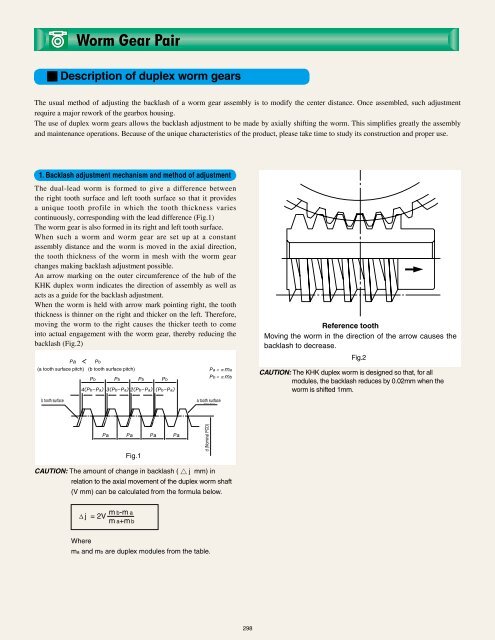
<strong>Worm</strong> <strong>Gear</strong> <strong>Pair</strong>■ Description of duplex worm gearsThe usual method of adjusting the backlash of a worm gear assembly is to modify the center distance. Once assembled, such adjustmentrequire a major rework of the gearbox housing.The use of duplex worm gears allows the backlash adjustment to be made by axially shifting the worm. This simplifies greatly the assemblyand maintenance operations. Because of the unique characteristics of the product, please take time to study its construction and proper use.1. Backlash adjustment mechanism and method of adjustmentThe dual-lead worm is formed to give a difference betweenthe right tooth surface and left tooth surface so that it providesa unique tooth profile in which the tooth thickness variescontinuously, corresponding with the lead difference (Fig.1)The worm gear is also formed in its right and left tooth surface.When such a worm and worm gear are set up at a constantassembly distance and the worm is moved in the axial direction,the tooth thickness of the worm in mesh with the worm gearchanges making backlash adjustment possible.An arrow marking on the outer circumference of the hub of theKHK duplex worm indicates the direction of assembly as well asacts as a guide for the backlash adjustment.When the worm is held with arrow mark pointing right, the tooththickness is thinner on the right and thicker on the left. Therefore,moving the worm to the right causes the thicker teeth to comeinto actual engagement with the worm gear, thereby reducing thebacklash (Fig.2)(a tooth surface pitch) (b tooth surface pitch)Reference toothMoving the worm in the direction of the arrow causes thebacklash to decrease.Fig.2CAUTION: The KHK duplex worm is designed so that, for allmodules, the backlash reduces by 0.02mm when theworm is shifted 1mm.b tooth surfacea tooth surfaceFig.1d (Nominal PCD)CAUTION: The amount of change in backlash ( △ j mm) inrelation to the axial movement of the duplex worm shaft(V mm) can be calculated from the formula below.m b-m aΔj = 2V m a+m bWherema and mb are duplex modules from the table.298