IPmux-24 - Tessco
IPmux-24 - Tessco
IPmux-24 - Tessco
You also want an ePaper? Increase the reach of your titles
YUMPU automatically turns print PDFs into web optimized ePapers that Google loves.
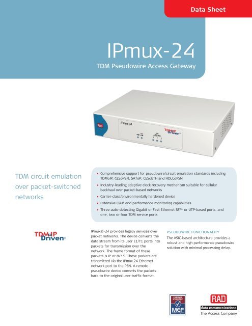
Data Sheet<strong>IPmux</strong>-<strong>24</strong>TDM Pseudowire Access GatewayTDM circuit emulationover packet-switchednetworks• Comprehensive support for pseudowire/circuit emulation standards includingTDMoIP, CESoPSN, SAToP, CESoETH and HDLCoPSN• Industry-leading adaptive clock recovery mechanism suitable for cellularbackhaul over packet-based networks• Carrier-class/environmentally hardened device• Extensive OAM and performance monitoring capabilities• Three auto-detecting Gigabit or Fast Ethernet SFP- or UTP-based ports, andone, two or four TDM service ports<strong>IPmux</strong>®-<strong>24</strong> provides legacy services overpacket networks. The device converts thedata stream from its user E1/T1 ports intopackets for transmission over thenetwork. The frame format of thesepackets is IP or MPLS. These packets aretransmitted via the <strong>IPmux</strong> <strong>24</strong> Ethernetnetwork port to the PSN. A remotepseudowire device converts the packetsback to the original user traffic format.PSEUDOWIRE FUNCTIONALITYThe ASIC-based architecture provides arobust and high performance pseudowiresolution with minimal processing delay.The Access Company
<strong>IPmux</strong>-<strong>24</strong>TDM Pseudowire Access GatewayThe unit supports various pseudowireencapsulation methods, including TDMoIP,CESoPSN, SAToP, CESoETH (MEF 8) andHDLCoPSN.Proper balance between PSN throughputand delay is achieved via configurablepacket size.A jitter buffer compensates for packetdelay variation (jitter) of up to 180 msecin the network.PSEUDOWIRE QoS/CoSEthernet networks – outgoing pseudowirepackets are assigned a dedicated VLAN IDaccording to 802.1q and marked forpriority using 802.1P bits.IP networks – outgoing pseudowirepackets are marked for priority usingDSCP, ToS, or Diffserv bits.MPLS networks – outgoing pseudowirepackets are assigned to a specific MPLStunnel and marked for priority using EXP bits.PSEUDOWIRE TIMINGEnd-to-end synchronization betweencircuits is maintained by deployingadvanced clock recovery mechanisms.Clock recovery conforms to G.823 andG.8<strong>24</strong> traffic interface usingG.8261-defined scenarios.Advanced clock recovery conforms toG.823 synchronization interface usingG.8261-defined scenarios and achieves16 ppb clock accuracy.The system clock ensures a single clocksource for all TDM links. The system clockuses master and fallback timing sourcesfor clock redundancy. <strong>IPmux</strong>-<strong>24</strong> alsoprovides system clock input and output viaan optional external clock port.TDM INTERFACEOne, two or four E1 or T1 ports provideconnectivity to any standard E1 or T1device.The E1 and T1 interfaces feature:• Integral LTU/CSU for long haulapplications• G.703 and G.704 framing modes• CAS and CRC-4 bit generation (E1)• D4/SF and ESF framing (T1)• Robbed bit (T1).Figure 1. 2G/3G Cellular Backhaul
Data SheetETHERNET INTERFACEThe following Ethernet ports are available:• One network port• One network/user port• One user port.The Ethernet ports accept a wide range ofGigabit and Fast Ethernet SFP-based fiberoptic and electric, as well as built-in UTPinterfaces.The unit can also be ordered with FastEthernet interfaces only (<strong>IPmux</strong>-<strong>24</strong>/FE).ETHERNET CAPABILITIES<strong>IPmux</strong>-<strong>24</strong> features an internal bridge,operating in VLAN-aware andVLAN-unaware modes.VLAN stacking can be used for trafficseparation between different users orservices, by defining a service providerVLAN ID per customer or service. WhenVLAN stacking is used, a service providerVLAN tag is added to the user traffic andremoved from network traffic. Bothservice provider VLAN ID and serviceprovider VLAN priority can be defined.<strong>IPmux</strong>-<strong>24</strong> provides four priority queues foreach port or pseudowire traffic flow. Usertraffic can be prioritized according toVLAN priority, DSCP, IP Precedence or perport.Ingress and egress rate can be limited peruser and network port. Rate limitation isconfigured per packet type.ETHERNET RINGThe unit employs Resilient Ethernet Ringtechnology to construct a self-healingEthernet fiber ring topology (ringresiliency is similar to that of SDH/SONETnetworks). In case of link failure on anysegment of the ring, the pseudowiretraffic is rerouted within 50 ms. A singlering supports up to 16 nodes.ETHERNET LINK PROTECTIONThe unit supports link aggregation (LAG)based on 802.3ad requirements.Dual homing technology (1:1) allows<strong>IPmux</strong>-<strong>24</strong> to be connected to twodifferent upstream devices.PSEUDOWIRE TRAFFIC PROTECTIONPseudowire traffic can be backed up atthe pseudowire connection level. Thisallows setting a different path for theprimary and secondary PW bundles. Bothbundles can be routed to the same ordifferent destinations and operate in the1+1 and 1:1 modes.In the 1:1 redundancy with two remotedevices the PW bundles in the remoteunits operate in the “mate” mode. In thismode each device monitors traffic activityon a mate bundle and transfers data onlywhen the other bundle is inactive.Figure 2. Private or Leased Line over PSN
<strong>IPmux</strong>-<strong>24</strong>TDM Pseudowire Access GatewayETHERNET SERVICE OAM (802.1ag)The unit uses the end-to-end Ethernetlayer OAM protocol for proactiveconnectivity monitoring, fault verification,and fault isolation, according to the IEEE802.1ag and ITU-T Y.1731 requirements.LINK OAM (IEEE 802.3ah)Link-layer OAM according to IEEE 802.3ahis used for fault indication and loopbackactivation response.MANAGEMENT<strong>IPmux</strong>-<strong>24</strong> can be configured andmonitored locally via an ASCII terminal, orremotely via Telnet/SSH, Web browser orRADview.Management traffic can run over adedicated VLAN.The RADview Service Center and ElementManager packages control and monitorpseudowire devices and circuits. TheService Center’s intuitive GUI, “point andclick”functionality and easy-to-followwizards increase the efficiency andaccuracy of the service provisioningprocess.<strong>IPmux</strong>-<strong>24</strong> performs RADIUS clientauthentication. Using SSH and SSLencryption protocols allows securecommunication over potentially insecureIP-based networks.The Syslog protocol is used by <strong>IPmux</strong>-<strong>24</strong>to generate and transport eventnotification messages over IP networks tothe central Syslog server. The Syslogoperation is compliant with the RFC 3164requirements.SNMPv3 support introduces a user-basedsecurity model, enhances authenticationand encryption techniques, and ensuresmanagement traffic security.Software is downloaded via the localterminal, using XMODEM, or remotely,using TFTP. After downloading a newsoftware version, <strong>IPmux</strong>-<strong>24</strong> automaticallysaves the previous version in non-volatilememory for backup purposes. Similarly,copies of the configuration file may bedownloaded and uploaded to a remoteworkstation for backup and restorepurposes.OAM AND DIAGNOSTICSThe following RFC-<strong>24</strong>95 E1/T1 physicallayer performance statistics are available:LOS, LOF, LCV, RAI, AIS, FEBE, BES, DM, ES,SES, UAS and LOMF.<strong>IPmux</strong>-<strong>24</strong> performs an internal built-in test(BIT) after power-up. The results of thetest are visible via the local terminal.LAN and IP layer network conditionstatistics, such as packet loss and packetdelay variation (jitter) are monitored andstored by the device.Fault isolation, statistics and event loggingare available.Fault propagation initiates service portalarms, e.g. E1/T1 LOS, to reflect networkfault conditions. Alarms detected atservice ports are propagated to theremote pseudowire device via the packetnetwork.Preserves investmentin legacy equipment inmigration to PSN
Data SheetDiagnostic loopbacks can be activatedinband.Ethernet and IP-layer network conditionstatistics, such as packet sequence errors(loss or misorder) and packet delayvariation (jitter), are monitored and storedby the device.RAD’s TDM PW OAM mechanism verifiesconnectivity, measures round trip delayand prevents pseudowire configurationmismatch.The carrier-class version of <strong>IPmux</strong>-<strong>24</strong>includes an alarm relay mechanism. Theminor and major alarms are forwarded toa remote alarm device via dedicated pinsof the external clock RJ-45 connector.ENVIRONMENT<strong>IPmux</strong>-<strong>24</strong>/H is an environmentally hardenedversion intended for street-cabinet andcellular-tower installations.Notes: The /H version requires temperaturehardened SFP transceivers.Figure 3. Delivering Ethernet and TDM Services over Fiber Ring in the First Mile
<strong>IPmux</strong>-<strong>24</strong>TDM Pseudowire Access GatewaySpecificationsE1 INTERFACENumber of Ports1, 2 or 4ComplianceITU-T Rec. G.703, G.704, G.706, G.732,G.823Data Rate2.048 MbpsLine CodeHDB3FramingUnframed, framed, multiframe; with orwithout CRC-4SignalingCAS, CCS (transparent)Line Impedance120Ω, balanced75Ω, unbalancedSignal LevelsReceive:0 to -36 dB with LTU (long haul)0 to -10 dB without LTU (short haul)Transmit balanced: ±3V ±10%Transmit unbalanced: ±2.37V ±10%Jitter and Wander PerformancePer AT&T TR-6<strong>24</strong>11, ITU-T G.8<strong>24</strong> (forinternal, loopback and external clockmodes)T1 INTERFACENumber of Ports1, 2 or 4ComplianceANSI T1.403, ITU-T Rec. G.703, G.704,G.8<strong>24</strong>Data Rate1.544 MbpsLine CodeB8ZS, B7ZS, AMIFramingUnframed, SF, ESFSignalingCAS (bit robbing), CCS (transparent)Line Impedance100Ω, balancedSignal LevelsReceive: 0 to -36 dBTransmit pulse amplitude:±3V ±20%; 0 dB, -7.5 dB, 15 dB (CSU),user-selectable±2.7V ±10%, 0 to 655 feet, (DSU),user-selectableJitter and Wander PerformancePer AT&T TR-6<strong>24</strong>11, ITU-T G.8<strong>24</strong> (forinternal, loopback and external clock modes)ConnectorRJ-45Lowers Opex of TDMservice by utilizingpacket infrastructureConnectorBalanced: RJ-45Unbalanced: BNC (RJ-45 to BNC adaptercable is supplied)
Data SheetETHERNET INTERFACEStandard ComplianceIEEE 802.3, 802.3u, 802.1p&QNumber of Ports3, network or userPort Combinations3 fiber optic SFPs2 fiber optic SFPs + 1 UTP1 fiber optic SFP + 2 UTPs3 UTPs (Fast Ethernet unit only)TypeSFP-based:Gigabit Ethernet – 1000BaseSx,1000BaseLX10, 1000BaseBx10Fast Ethernet –100BaseFx,100BaseLX10, 100BaseBx1010/100/1000BaseT with SGMIIBuilt-in:10/100BaseTFast and Gigabit Ethernet SPFsFor full details, see the SFP Transceiversdata sheet at www.rad.comNote: It is strongly recommended to order thisdevice with original RAD SFPs installed. This willensure that prior to shipping, RAD has performedcomprehensive functional quality tests on theentire assembled unit, including the SFP devices.RAD cannot guarantee full compliance to productspecifications for units using non-RAD SFPs.For detailed specifications of the SFP transceivers,see the SFP Transceivers data sheet.ConnectorLCPSEUDOWIREStandard ComplianceIETF: RFC 4553 (SAToP), RFC 5087(TDMoIP), RFC 5086 (CESoPSN),RFC 4618 (excluding clause 5.3 – PPP)ITU-T: Y.1413MFA: IA 4.1, IA 8.0.0MEF: 8, 9, 14 (EPL-certified)Number of PW Connections64Jitter Buffer Size0.5–180 msec (unframed) with 0.1 msecgranularity2.5–180 msec (framed) with 0.5 msecgranularity<strong>IPmux</strong>-<strong>24</strong>/A Adaptive ClockFrequency accuracy: ±16 ppb and G.823synchronization interface requirements(clause 6), when locked to a PRC(stratum 1) or SSU (stratum 2) clockFrequency accuracy in holdover: ±16 ppb±1 ppb of aging per dayFigure 4. Drop-and-Insert of Full and Fractional E1/T1 Circuits and Ethernet over Fiber
<strong>IPmux</strong>-<strong>24</strong>TDM Pseudowire Access GatewayGENERALTimingInternalLoopbackAdaptiveExternal input or output via optionaldedicated RJ-45 port: E1/T1 or2048/1544 kHz squarewave (RS-422electrical levels)ManagementSNMPv1, SNMPv3TelnetRADview Service Center TDMoIP (orderedseparately)ASCII terminal via V.<strong>24</strong> (RS-232) DCE portDiagnosticsE1/T1 local loopbackE1/T1 remote loopbackFacility Type 1 (FAC1) inband loopbackCSU loopback as per Telecordia GR-54StatisticsE1/T1 (per G.826 and RFC <strong>24</strong>95)Ethernet (per RFC 2819)Jitter buffer indication (overflow,underflow, sequence error)Alarm RelayVia pin 6, pin 7 and pin 8 of the EXT. CLKconnector (RJ-45), optionalIndicatorsPWR (green) – Power statusTST/ALM (red/yellow) – Test/alarm statusE1/T1 SYNC (green/red) – E1/T1synchronization statusLINK/ACT (green) – Ethernet link/activitystatusEXT. CLK (red/green) – External clockstatusPowerAC/DC: 100–<strong>24</strong>0 VAC, 50/60 Hz or48/60 VDC nominal (40 to 72 VDC)DC: <strong>24</strong> VDC nominal (18–36 VDC)Power Consumption12W maxPhysicalHeight: 47 mm (1.8 in)Width: 215 mm (8.4 in)Depth: 147 mm (5.8 in)Weight: 0.7 kg (1.5 lb)EnvironmentTemperature:<strong>IPmux</strong>-<strong>24</strong>: 0 to 50°C (32 to 122°F)<strong>IPmux</strong>-<strong>24</strong>/H: -30 to 65°C(-22 to 149°F)Humidity: Up to 90%, non-condensingCarrier-grade voicequality withoutcompression, orsilence suppression
Data SheetTable 1. <strong>IPmux</strong> Family Product ComparisonFeature<strong>IPmux</strong>-2L(Ver. 1.0)<strong>IPmux</strong>-14(Ver. 2.0)<strong>IPmux</strong>-<strong>24</strong>(Ver. 2.1)<strong>IPmux</strong>-216(Ver. 2.1)TDM service ports 1, 2 (E1 only) 2, 4 1, 2, 4 8, 16Ethernet network ports 1 × FE 1 × FE network,1 × FE network/user1 × GbE/FE network,1 × GbE/FE network/user1 × GbE/FE network,1 × GbE/FE network/userEthernet subscriber 1 or 2 × FE 1 × FE 1 × GbE/FE 1 × GbE/FEportsNumber of PWs 63 64 64 256Advanced clock recovery – (OCXO)Redundant power supply – – – External clock port – Optional Optional Serial data port Optional Optional – –SSH, SSL, RADIUS – – NMS RV-EMS/NGN RV-SC/TDMoIP RV-SC/TDMoIP RV-SC/TDMoIP
<strong>IPmux</strong>-<strong>24</strong>TDM Pseudowire Access GatewayOrdering<strong>IPmux</strong>-<strong>24</strong>/#/!/?/~/*/$/+1/+2/+3Legend# Ethernet interface (Default=FE and GbEcapabilities)FE Fast Ethernet interface only! Power supply type (Default=AC/DCpower supply):WRDC Wide range DC power supply forenvironmentally hardeneddevice? Enclosure (Default=regular device):H Environmentally hardeneddevice~ Clock recovery (Default=standard clockrecovery):A Advanced clock recoverymechanism (per TDM port)* Package (Default=no carrier-classpackage)C Carrier-class package (externalclock and alarm relay)$ TDM interface:1E1 Single balanced E1 interface1E1CX Single unbalanced E1 interface1T12E1Single balanced T1 interface2 balanced E1 interfaces2E1CX 2 unbalanced E1 interfaces+1 Network interface:N SFP-ready slot1 Fast Ethernet/STM-1, 1310 nm,multimode, LED, 2 km (1.2 mi)2 Fast Ethernet/STM-1, 1310 nm,single mode, laser, 15 km(9.3 mi)2HFast Ethernet/STM-1, industriallyhardened, 1310 nm, single mode,laser, 15 km (9.3 mi)3 Fast Ethernet/STM-1, 1310 nm,single mode, laser, 40 km(<strong>24</strong>.8 mi)3HFast Ethernet/STM-1, industriallyhardened, 1310 nm, single mode,laser, 40 km (<strong>24</strong>.8 mi)4 Fast Ethernet/STM-1, 1550 nm,single mode, laser, 80 km(49.7 mi)10A Fast Ethernet/STM-1, Tx –1310 nm, Rx – 1550 nm, singlemode (single fiber), laser (WDM), 20 km (12.4 mi)10B Fast Ethernet/STM-1, Tx –1550 nm, Rx – 1310 nm, singlemode (single fiber), laser (WDM), 20 km (12.4 mi)18A Fast Ethernet/STM-1, Tx –1310 nm, Rx – 1550 nm, 9/25single mode (single fiber), laser(WDM), 40 km (<strong>24</strong>.8 mi)18B Fast Ethernet/STM-1, Tx –1550 nm, Rx – 1310 nm, 9/25single mode (single fiber), laser(WDM), 40 km (<strong>24</strong>.8 mi)19A Fast Ethernet/STM-1, Tx –1490 nm, Rx – 1570 nm, 9/25single mode (single fiber), laser(WDM) , 80 km (49.7 mi)19B Fast Ethernet/STM-1, Tx –1570 nm, Rx – 1490 nm, 9/25single mode (single fiber), laser(WDM) , 80 km (49.7 mi)2T14E12 balanced T1 interfaces4 balanced E1 interfaces4E1CX 4 unbalanced E1 interfaces4T1 4 balanced T1 interfacesNote: Unbalanced E1 interfaces are provided viaRJ-45 to BNC adapter cables supplied with theproduct.
Data Sheet5 Gigabit Ethernet, 850 nm,multimode, VCSEL, 0.55 km(0.3 mi)5HGigabit Ethernet, industriallyhardened, 850 nm, multimode,VCSEL, 0.55 km (0.3 mi)6 Gigabit Ethernet, 1310 nm, singlemode, laser, 10.0 km (6.2 mi)6HGigabit Ethernet, industriallyhardened, 1310 nm, single mode,laser, 10.0 km (6.2 mi)7 Gigabit Ethernet, 1550 nm, singlemode, laser, 80.0 km (49.7 mi)8 Gigabit Ethernet, 1310 nm, singlemode, laser, 40.0 km (<strong>24</strong>.8 mi)8HGigabit Ethernet, industriallyhardened, 1310 nm, single mode,laser, 40.0 km (<strong>24</strong>.8 mi)17A Gigabit Ethernet, Tx -1310 nm, Rx-1490 nm, single mode (singlefiber), laser (WDM), 10.0 km(6.2 mi)17B Gigabit Ethernet, Tx -1490 nm, Rx-1310 nm, single mode (singlefiber), laser (WDM), 10.0 km(6.2 mi)20 Gigabit Ethernet, 1550 nm, singlemode, laser, 120.0 km (74.5 mi)22A Gigabit Ethernet, Tx -1490 nm, Rx-1570 nm, single mode (singlefiber), laser (WDM), 80.0 km(49.7 mi)22B Gigabit Ethernet, Tx -1570 nm, Rx-1490 nm, single mode (singlefiber), laser (WDM), 80.0 km(49.7 mi)9F9GFast Ethernet, RJ-45 connector,100m (238 ft)GbE interface, RJ-45 connector,100m (238 ft)30 10/100/1000BaseT (with SGMII),RJ-45 connector, 100m (238 ft)UTP Built-in 10/100BaseT+2 Network/user interfaceSee the network interface orderingoptions aboveNote: It is strongly recommended to order thisdevice with original RAD SFPs installed. This willensure that prior to shipping, RAD has performedcomprehensive functional quality tests on theentire assembled unit, including the SFP devices.RAD cannot guarantee full compliance to productspecifications for units using non-RAD SFPs.For detailed specifications of the SFP transceivers,refer to the SFP Transceivers data sheet.+3 User interface type:See the network/user interfaceordering options aboveTable 2. Valid Port CombinationsNetwork Network/User UserN N NN N UTPN UTP UTPUTP UTP UTPUTP UTP NUTP N NNote: The N (SFP-ready slot) option in Table 1 canbe replaced with any SFP transceiver supported by<strong>IPmux</strong>-<strong>24</strong>.
<strong>IPmux</strong>-<strong>24</strong>TDM Pseudowire Access GatewayData SheetSUPPLIED ACCESSORIESPower cordAC/DC adapter plugCBL-RJ45/2BNC/E1/XRJ-45 to BNC adapter cable (if anunbalanced E1 interface is ordered)OPTIONAL ACCESSORIESRM-35/@Hardware kit for mounting one or two<strong>IPmux</strong>-<strong>24</strong> units into a 19-inch rackLegend@ Rack mounting kit (Default=both kits):P1 Kit for mounting one unitP2 Kit for mounting two unitsCBL-DB9F-DB9M-STRControl port cable488-100-07/09 Specifications are subject to change without prior notice. © 1997–2009 RAD Data Communications Ltd. The RAD name, logo, logotype, and the terms EtherAccess, TDMoIP and TDMoIP Driven, and theproduct names Optimux and <strong>IPmux</strong>, are registered trademarks of RAD Data Communications Ltd. All other trademarks are the property of their respective holders.International Headquarters<strong>24</strong> Raoul Wallenberg StreetTel Aviv 69719, IsraelTel. 972-3-6458181Fax 972-3-6498250, 6474436E-mail market@rad.comNorth America Headquarters900 Corporate DriveMahwah, NJ 07430, USATel. 201-5291100Toll free 1-800-4447234Fax 201-5295777E-mail market@rad.comwww.rad.com Order this publication by Catalog No. 803782The Access Company


