Functional Safety
Functional Safety
Functional Safety

Create successful ePaper yourself
Turn your PDF publications into a flip-book with our unique Google optimized e-Paper software.
White Paper<br />
<strong>Functional</strong> <strong>Safety</strong>: A Practical Approach for<br />
End-Users and System Integrators<br />
Date: 01 June 2006<br />
Author(s): Tino Vande Capelle<br />
Dr. M.J.M. Houtermans<br />
HIMA Paul Hildebrandt GmbH Co KG<br />
Albert-Bassermann-Strasse 28<br />
68782 Bruehl<br />
Germany<br />
www.hima.com<br />
HIMA <strong>Functional</strong> <strong>Safety</strong> Consulting Services
White Paper<br />
Tino Vande Capelle, Dr. M.J.M. Houtermans<br />
<strong>Functional</strong> <strong>Safety</strong>: A Practical Approach<br />
for End-Users and System Integrators<br />
Title: <strong>Functional</strong> <strong>Safety</strong>: A Practical Approach<br />
for End-Users and System Integrators<br />
Date: 01 June 2006<br />
Author(s): Tino Vande Capelle<br />
Dr. M.J.M. Houtermans<br />
© 2006 HIMA<br />
All Rights Reserved<br />
LIMITATION OF LIABILITY - This report was prepared using best efforts. HIMA does not accept any responsibility for<br />
omissions or inaccuracies in this report caused by the fact that certain information or documentation was not made available to<br />
us. Any liability in relation to this report is limited to the indemnity as outlined in our Terms and Conditions. A copy is available<br />
at all times from our website at www.hima.com.<br />
Printed in Germany<br />
This document is the property of, and is proprietary to HIMA. It is not to be disclosed in whole or in part and no portion of this<br />
document shall be duplicated in any manner for any purpose without Hima’s expressed written authorization.<br />
HIMA, the HIMA logo, are registered service marks.<br />
HIMA <strong>Functional</strong> <strong>Safety</strong> Consulting Services Page 2
White Paper<br />
Tino Vande Capelle, Dr. M.J.M. Houtermans<br />
<strong>Functional</strong> <strong>Safety</strong>: A Practical Approach<br />
for End-Users and System Integrators<br />
FUNCTIONAL SAFETY: A PRACTICAL APPROACH<br />
FOR END-USERS AND SYSTEM INTEGRATORS<br />
TINO VANDE CAPELLE 1 2, 3<br />
, Dr. MICHEL HOUTERMANS<br />
1- HIMA Paul Hildebrandt GmbH + Co KG, Brühl, GERMANY<br />
2 – Risknowlogy, Brunssum, THE NETHERLANDS<br />
3 - TUV Rheinland Group, Köln, GERMANY<br />
tinovdc@hima.com, m.j.m.houtermans@risknowlogy.com,<br />
michel.houtermans@de.tuv.com http://www.hima.com, http://www.risknowlogy.com<br />
Abstract: - The objective of this paper is to demonstrate through a practical example how an<br />
end-user should deal with functional safety while designing a safety instrumented function<br />
and implementing it in a safety instrumented system. The paper starts with explaining the<br />
problems that exist inherently in safety systems. After understanding the problems the paper<br />
takes the reader from the verbal description of a safety function through the design of the<br />
architecture, the process for the selection of safety components, and the role of reliability<br />
analysis. After reading this paper the end-users understands the practical process for<br />
implementing the design of safety instrumented systems without going into detail of the<br />
requirements of the standard.<br />
Key-Words: - <strong>Functional</strong> <strong>Safety</strong> – Hazard – Risk – <strong>Safety</strong> Instrumented Systems – <strong>Safety</strong><br />
Integrity Level –Reliability – PFD – PFH.<br />
1. Introduction<br />
Every day end-users around the world are struggling with the design, implementation,<br />
operation, maintenance and repair of safety instrumented systems. The required<br />
functionality and safety integrity of safety instrumented systems is in practice determined<br />
through a process hazard analysis. This task is typically performed by the end-users as they<br />
are the experts on their own production processes and understand the hazards of their<br />
processes best. The result of such a process hazard analysis is among others a verbal<br />
description of each required safety function needed to protect the process. These safety<br />
functions are allocated to one or more safety systems, which can be of different kinds of<br />
technology. Those safety systems that are based on electronic or programmable electronic<br />
technology need as a minimum to comply with the functional safety standards IEC 61508<br />
and/or 61511.<br />
The end-user is typically not involved in the actual design of the safety system. Normally this<br />
is outsourced to a system integrator. The system integrator determines the design of the<br />
safety system architecture and selects the safety components based on the specification of<br />
the end-users. No matter who designs the safety system according to the safety function<br />
requirements, in the end it is the end-user who is responsible for the safety integrity of the<br />
safety system. This means that the end-user needs to assure him that the chosen safety<br />
architecture and the selected safety components meet the requirements of the applicable<br />
standards and be able to defend its decision to any third party performing the functional<br />
safety assessment.<br />
HIMA <strong>Functional</strong> <strong>Safety</strong> Consulting Services Page 3
White Paper<br />
Tino Vande Capelle, Dr. M.J.M. Houtermans<br />
<strong>Functional</strong> <strong>Safety</strong>: A Practical Approach<br />
for End-Users and System Integrators<br />
In reality end-users and system integrators are not experts in hardware and software design<br />
of programmable electronic systems. They know how to run and automate chemical or oil &<br />
gas plants but most likely they are not experts on how the operating system of a logic<br />
solvers works or whether the communication ASIC of the transmitter is capable of fault free<br />
safe communication. Even if they would be experts, the suppliers of the safety components<br />
will not give them sufficient information about the internals of the devices so that they can<br />
assure themselves of the safety integrity of these devices. Yet they are responsible for the<br />
overall design and thus they need to assure themselves that functional safety is achieved.<br />
But how can they deal with that in practice?<br />
The objective of this paper is to demonstrate through a practical example how an end-user<br />
and/or system integrator should deal with functional safety while designing a safety<br />
instrumented function and implementing it in a safety instrumented system. The paper starts<br />
with explaining the problems that exist inherently in safety systems. After understanding the<br />
problems the paper takes the reader from the verbal description of a safety function through<br />
the design of the architecture, the process for the selection of safety components, and the<br />
role of reliability analysis. After reading this paper the end-users understands the practical<br />
process for implementing the design of safety instrumented systems without going into detail<br />
of the requirements of the standard.<br />
2. Why <strong>Safety</strong> Systems Fail<br />
The hardware of a safety instrumented system can consist of sensors, logic solvers,<br />
actuators and peripheral devices. With a programmable logic solver there is also application<br />
software that needs to be designed. An end-user in the process industry uses as basis for<br />
the design and selection of the safety devices the IEC 61511 standard. This standard<br />
outlines requirements for the hardware and software and refers to the IEC 61508 standard if<br />
the requirements of the IEC 61511 cannot be not met. This means that even if the IEC<br />
61511 standard is used as basis some of the hardware and software needs to comply with<br />
IEC 61508.<br />
As with any piece of equipment also safety equipment can fail. One of the main objectives of<br />
the IEC 61508 standard is to design a “safe” safety system. A “safe” safety system means a<br />
system that is designed in a way that it can either tolerate internal failures, and still execute<br />
the safety function, or if it cannot carry out the safety function any more it at least can notify<br />
an operator via an alarm. If we want to design a safe safety system we should first<br />
understand how safety systems can fail. According to IEC 61508 equipment can fail<br />
because of three types of failures, i.e.,<br />
� Random hardware failures,<br />
� Common cause failures and<br />
� Systematic failures.<br />
2.1 Random Hardware Failures.<br />
Random hardware failures are failures that can occur at any given point in time because of<br />
internal degradation mechanisms in the hardware. A typical example is wear out. Any<br />
rotating or moving equipment will eventually wear out and fail. There are two kinds of<br />
random hardware failures (Rouvroye et. al., 1997):<br />
� Permanent<br />
� Dynamic<br />
HIMA <strong>Functional</strong> <strong>Safety</strong> Consulting Services Page 4
White Paper<br />
Tino Vande Capelle, Dr. M.J.M. Houtermans<br />
<strong>Functional</strong> <strong>Safety</strong>: A Practical Approach<br />
for End-Users and System Integrators<br />
Permanent random hardware failures exist until they are repaired. This in contrast to the<br />
dynamic random hardware failures. They only appear under certain conditions (for example<br />
when the temperature is above 80 C). When the condition is removed the failure disappears<br />
again. It is very difficult to test hardware for random dynamic hardware failures.<br />
The IEC 61508 standard addresses random failures in two ways. First of all IEC 61508<br />
requires a designer to implement measures to control failures. The appendix of IEC 61508<br />
part 2 contains tables (Table A16-A18) which represent per SIL level measures that need to<br />
be implemented in order to control failures that might occur in hardware.<br />
Secondly, IEC 61508 requires a qualitative and quantitative failure analysis on the<br />
hardware. Via a failure mode and effect analysis the failure behaviour of the equipment<br />
needs to be analysed and documented. For the complete safety function it is necessary to<br />
carry out a probabilistic reliability calculation to determine the average probability of failure<br />
on demand of the safety function.<br />
2.2 Common Cause Failures<br />
A common cause failure is defined as a failure, which is the result of one or more events,<br />
causing coincident failures of two or more separate channels in a multiple channel system,<br />
leading to total system failure. Thus a common cause can only occur if the safety function is<br />
carried out with hardware more than once (dual, triple, quadruple, etc. redundancy).<br />
Common cause failures are always related to environmental issues like temperature,<br />
humidity, vibration, EMC, etc. If the cause is not related to environmental circumstances<br />
than it is not a common cause. Typical examples of a common cause could be a failure of a<br />
redundant system due to flooding with water or an EMC field. A common cause failure is<br />
only related to hardware, and not to software. A software failure is a systematic failure which<br />
is addressed in the next paragraph.<br />
The IEC 61508 standard has two ways to address common cause failures. First of all there<br />
is one measure defined to control failures defined, i.e., diversity. Diversity still means that we<br />
carry out the safety function in a redundant manner but we use different hardware, or a<br />
different design principle or even completely different technology to carry out the same<br />
safety function. For example if we use a pure mechanical device and a programmable<br />
electronic device to carry out the safety function then a common cause failure of the safety<br />
function due to an EMC field will never occur. The programmable electronic device might fail<br />
due to EMC but the pure mechanical device will never fail due to EMC.<br />
In practice a real common cause is difficult to find because the failures of a multi channel<br />
system must per definition of a common cause occur at exactly the same time. The same<br />
hardware will always have different strength and thus fail at slightly a different time. A well<br />
designed safety system can take advantage of this gap in time and detect one failure before<br />
the other failure occurs.<br />
2.3 Systematic Failures<br />
The most important failures to manage in safety system are the systematic failures. A<br />
systematic failure is defined as a failure related in a deterministic way to a certain cause,<br />
which can only be eliminated by a modification of the design or of the manufacturing<br />
HIMA <strong>Functional</strong> <strong>Safety</strong> Consulting Services Page 5
White Paper<br />
Tino Vande Capelle, Dr. M.J.M. Houtermans<br />
<strong>Functional</strong> <strong>Safety</strong>: A Practical Approach<br />
for End-Users and System Integrators<br />
process, operational procedures, documentation or other relevant factors. A systematic<br />
failure can exist in hardware and software.<br />
Systematic failures are the hardest failures to eliminate in a safety system. One can only<br />
eliminate systematic failures if they are found during testing. Testing that either takes place<br />
during the development and design of the safety system or testing that takes place when the<br />
system exist in the field (so called proof test). The problem that systematic failures only can<br />
be found if a specific test is carried out to find that failure. If we do not test for it we do not<br />
find it.<br />
The IEC 61508 standard addresses systematic failure in only one way. The standard<br />
defines measures to avoid failures for hardware as well as software. These measures are<br />
presented in the appendix of part 2 and 3 of IEC 61508 (respectively tables B1-B5 and<br />
tables A1-B9) and depend on the required safety integrity. The standard does not take<br />
systematic failures into account in the failure analysis. The philosophy behind this is simple.<br />
If all the required measures to avoid failures are implemented and correctly carried out then<br />
there are no systematic failures (or at least it is negligible for the desired safety integrity) and<br />
thus the contribution to the probability of failure is (close to) zero.<br />
2.4 End-user Responsibility<br />
All though the end-user has no control over the actual design and internal testing of safety<br />
equipment ultimately they are still responsible when accidents occur due to any of the three<br />
types of failures mentioned above. They need to assure themselves that the safety<br />
equipment selected by themselves or their system integrators is compliant with either the<br />
IEC 61508 or the IEC 61511 standard. In practice though end-users nor system integrators<br />
do not have the knowledge to understand what is going inside safety equipment. They will<br />
have to rely on third party assessments of this equipment to assure themselves that the<br />
equipment is suitable for their safety application. More on this topic is presented in<br />
paragraph 4.<br />
3. FROM HAZARD AND RISK ANALYSIS TO SPECIFICATION TO DESIGN<br />
A safety requirement specification of a safety system must at all times be based on the<br />
hazard and risk analysis. A good hazard and risk analysis includes the following steps:<br />
� Hazard identification<br />
� Hazard analysis (consequences)<br />
� Risk analysis<br />
� Risk management<br />
o Tolerable risk<br />
o Risk reduction through existing protection layers<br />
o Risk reduction through additional safety layers<br />
Many techniques exist to support hazard identification and analysis. There is not one<br />
ultimate technique that can do it all. A serious hazard and risk study is be based on the use<br />
of several techniques and methods. Typical hazard identification techniques include:<br />
� Checklists<br />
� What if study<br />
� Failure mode and effect analysis (FMEA)<br />
� Hazard and operability analysis (HAZOP)<br />
� Dynamic flowgraph methodology (DFM)<br />
HIMA <strong>Functional</strong> <strong>Safety</strong> Consulting Services Page 6
White Paper<br />
Tino Vande Capelle, Dr. M.J.M. Houtermans<br />
<strong>Functional</strong> <strong>Safety</strong>: A Practical Approach<br />
for End-Users and System Integrators<br />
Hazard analysis techniques include:<br />
� Event tree analysis (ETA)<br />
� Fault tree analysis (FTA)<br />
� Cause consequence analysis<br />
Risk reduction techniques include:<br />
� Event tree analysis (ETA)<br />
� Layer of protection analysis (LOPA, a variation on ETA)<br />
More techniques exist then the ones listed above that can be used to carry out the hazard<br />
and risk analysis. It is important to select the right technique for the right kind of analysis and<br />
not to limit oneself to one technique.<br />
3.1 <strong>Safety</strong> Requirement Specification.<br />
The hazard and risk analysis should among others document in a repeatable and traceable<br />
way those hazards and hazard events that require protection via an additional safety<br />
function. The results from the hazard and risk analysis are used to create the safety<br />
requirement specification of each safety function needed to protect the process. The<br />
specification as a minimum defines the following 5 elements for each safety function:<br />
� Sensing<br />
� Logic solving<br />
� Actuating<br />
� <strong>Safety</strong> integrity in terms of reliability<br />
� Timing<br />
Each safety function description should as a minimum consist of these five elements. The<br />
sensing element of the specification describes what needs to be sensed (e.g., temperature,<br />
pressure, speed, etc.). The logic solving element describes what needs to be done with the<br />
sensing element when it meets certain conditions (e.g., if the temperature goes over 65 C<br />
then actuate the shutdown procedure). The actuating element explains what actually needs<br />
to be done when the logic solving elements meets the conditions to be met (e.g., open the<br />
drain valve).<br />
So far we have described the functionality of the safety function. But the functionality is not<br />
complete if we do not know with how much safety integrity this needs to be carried out. The<br />
safety integrity determines how reliable the safety function needs to be. The functional<br />
safety standards have technical and non-technical safety integrity requirements that are<br />
based on the so called safety integrity level. There are four safety integrity levels (1 through<br />
4) where 1 is the lowest integrity level and 4 the highest. In other words it is much more<br />
difficult to build a SIL 4 safety function than it is to build a SIL 1 function. The SIL level<br />
determines not only the measures to avoid and to control failures that need to be<br />
implemented but also the required probability of failure on demand (PFD). The higher the<br />
SIL level the lower the probability of failure on demand of this safety function.<br />
The last element to be described is how fast the safety function should be carried out. Also<br />
this is a critical element as it depends on the so-called process safety time. This is the time<br />
the process needs to develop a potential hazard into a real incident. For example, mixing<br />
two chemicals at 30 C is not a problem at all. Mixing the same two chemicals at 50 C can<br />
HIMA <strong>Functional</strong> <strong>Safety</strong> Consulting Services Page 7
White Paper<br />
Tino Vande Capelle, Dr. M.J.M. Houtermans<br />
<strong>Functional</strong> <strong>Safety</strong>: A Practical Approach<br />
for End-Users and System Integrators<br />
lead to a runaway reaction and result in an explosion. The process safety time is the time<br />
the reaction needs to develop into an explosion.<br />
It is common practice in the safety industry to define the time element of the safety function<br />
as half of the process safety time. If the chemical reaction takes 2 hours to develop then we<br />
have 1 hour to carry out our safety function. On the other hand if the reaction takes 10<br />
seconds we have only 5 seconds to carry out the safety function. It is of up most importance<br />
to know this time for two reasons. First of all we need to build a safety function that can<br />
actually be carried out in this time. Each device used to carry out the safety function takes a<br />
piece of the available total time slot. If we for example use valves that need to be closed we<br />
need to make sure that these valves can close fast enough. The second reason is that we<br />
need to know whether the build-in diagnostics can diagnose a failure in less than half of the<br />
process safety time. Before we need to actuate the safety function we should be able to<br />
know whether the safety system has not failed. This puts extra constraints on the internal<br />
design of the safety devices when it comes to implementing fast enough diagnostics.<br />
The following is a bad example of a specified safety function:<br />
“The main safety function of the HIPPS is to protect the separation vessels against<br />
overpressure and to protect the low pressure equipment against high pressure.”<br />
There is no system integrator who can build the hardware and software from this definition.<br />
The only clear aspect is the sensing element. Some where the pressure needs to be<br />
measured. After that the system integrator will be lost. The logic, actuating, safety integrity<br />
and timing element are not covered with this specification. Specification like this will cost<br />
every party involved in the project more time than necessary. It will lead to a lot of<br />
unnecessary discussion. A much better example of a safety function specification is the<br />
following:<br />
“Measure the pressure on two locations in vessel XYZ and if the pressure exceeds the highhigh<br />
pressure limit open the drain valve within 3 seconds. Perform the function with a safety<br />
integrity of SIL 3.”<br />
This specification gives much more complete information. The system integrator knows<br />
exactly what the function should do and can now design the function according to the rules<br />
of SIL 3 and select components and write application software that can perform this<br />
function.<br />
For each safety function the end-user should provide the system integrator with a clear<br />
definition containing as a minimum the 5 elements specified before. There are many other<br />
requirements that the end-user can put into the specification. For example environmental<br />
conditions that the safety system should be able to handle (temperature ranges, humidity<br />
levels, vibration levels, EMC levels, etc.) or restart procedures, periodic test intervals, and<br />
more.<br />
A good system integrator will take the safety requirements specification of the end-user and<br />
translate that into a requirement specification that is usable for the system integrator. The<br />
specification created by the system integrator should be verified and approved by the enduser.<br />
This is an excellent step to be performed as it assures that both parties can see that<br />
they understand each other and that they interpreted the system to be designed correctly.<br />
HIMA <strong>Functional</strong> <strong>Safety</strong> Consulting Services Page 8
White Paper<br />
Tino Vande Capelle, Dr. M.J.M. Houtermans<br />
<strong>Functional</strong> <strong>Safety</strong>: A Practical Approach<br />
for End-Users and System Integrators<br />
Needless to say this costs a more time during specification which is saved during actual<br />
design and testing and the often required modifications after words.<br />
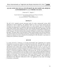
3.2 Architectural Design <strong>Safety</strong> Function<br />
When the safety requirements specification is clear and agreed upon the system integrator<br />
can start with the architectural design of the safety function and system. Figure 1 shows how<br />
a safety function definition can be implemented in hardware. The safety function is divided<br />
into three subsystems, i.e., sensing, logic solving, and actuating. The designer of the safety<br />
function can decide how to divide the safety function into subsystem and to what level or<br />
detail. In practice subsystems are determined by redundancy aspects or whether the<br />
component can still be repaired or not by the end-user.<br />
T1 TM 1<br />
T2 TM 2<br />
Measure the temperature in the reactor and if the temperature exceeds 65 C<br />
then open the drain valve and stop the supply pumps to the reactor. This function<br />
needs to be carried out within 3 seconds and with safety integrity SIL 3<br />
Sensing Logic Solving Actuating<br />
I1<br />
I2<br />
I3<br />
I4<br />
I5<br />
I6<br />
I7<br />
I8<br />
Common Circuitry<br />
CPU<br />
HIMA <strong>Functional</strong> <strong>Safety</strong> Consulting Services Page 9<br />
Common Circuitry<br />
O1<br />
O2<br />
O3<br />
O4<br />
O5<br />
O6<br />
O7<br />
O8<br />
R1- Pump A<br />
R2- Pump B<br />
SOV Drain V<br />
Fig. 1. From specification to hardware design of the safety instrumented system<br />
The IEC 61508 and IEC 61511 standard have set limitations on the architecture of the<br />
hardware. The concepts of the architectural constraints are the same for both standards<br />
although the IEC 61508 standard requires some more detail. The architectural constraints of<br />
the IEC 61508 standard are shown in Table 1 and 2 and are based on the following aspects<br />
per subsystem:<br />
� SIL level safety function<br />
� Type A or B<br />
� Hardware fault tolerance<br />
� Safe failure fraction
White Paper<br />
Tino Vande Capelle, Dr. M.J.M. Houtermans<br />
<strong>Functional</strong> <strong>Safety</strong>: A Practical Approach<br />
for End-Users and System Integrators<br />
Table 1 Architectural Constraints Type A<br />
Safe Failure<br />
Type A Subsystem<br />
Hardware Fault Tolerance<br />
(HFT)<br />
Fraction (SFF) 0 1 2<br />
< 60 % SIL 1 SIL 2 SIL 3<br />
60 % -< 90% SIL 2 SIL 3 SIL 4<br />
90 % -< 99% SIL 3 SIL 4 SIL 4<br />
> 99 % SIL 3 SIL 4 SIL 4<br />
Table 2 Architectural Constraints Type B<br />
Safe Failure<br />
Type B Subsystem<br />
Hardware Fault Tolerance<br />
(HFT)<br />
Fraction (SFF) 0 1 2<br />
< 60 % N.A. SIL 1 SIL 2<br />
60 % -< 90% SIL 1 SIL 2 SIL 3<br />
90 % -< 99% SIL 2 SIL 3 SIL 4<br />
> 99 % SIL 3 SIL 4 SIL 4<br />
The “type” designation of a subsystem refers to the internal complexity of the subsystem. A<br />
type A subsystem has a defined failure behaviour and the effect of every failure mode of the<br />
subsystem is clearly defined and well understood. Typical type A components are valves<br />
and actuators. A subsystem is of type B if only one failure mode and its effect cannot be<br />
understood. In practice any subsystem with an integrated circuit (IC) is per definition a type<br />
B. Typical type B systems are programmable devices like logic solvers, smart transmitter, or<br />
valve positioners.<br />
The hardware fault tolerance (HFT) determines the number of faults that can be tolerated<br />
before the safety function is lost. It is thus a measure of redundancy. When determining the<br />
hardware fault tolerance one should also take into account the voting aspects of the<br />
subsystem. A 1oo3 and 2oo3 subsystem carry out the safety function 3 times (triple<br />
redundant) but because of the voting aspect the HFT of the 1oo3 subsystem equals 2 and<br />
the HFT of the 2oo3 subsystem equals 1. A complete overview of the most common<br />
architectures is given in Table 3.<br />
Table 3 Redundancy versus HFT<br />
Architecture / Voting Redundancy HFT<br />
1oo1 No redundancy 0<br />
1oo2 Dual 1<br />
2oo2 No redundancy 0<br />
1oo3 Triple 2<br />
2oo3 Triple 1<br />
2oo4 Quadruple 2<br />
HIMA <strong>Functional</strong> <strong>Safety</strong> Consulting Services Page 10
White Paper<br />
Tino Vande Capelle, Dr. M.J.M. Houtermans<br />
<strong>Functional</strong> <strong>Safety</strong>: A Practical Approach<br />
for End-Users and System Integrators<br />
Another important factor is the safe failure fraction (SFF). This is basically a measure of the<br />
fail safe design and build-in diagnostics of the subsystem. A subsystem can fail safe or<br />
dangerous. Safe failures are those failures that case the subsystem to carry out the safety<br />
function without a demand. For example, the safety function of an emergency shutdown<br />
valve is to close upon demand. We call it a safe failure if the valve closes because of an<br />
internal failure without an demand. A dangerous failure is the opposite. The valve has failed<br />
dangerous if it cannot close upon demand because of an internal failure. Some components<br />
also have internal diagnostics (diagnostics should not be confused with proof testing). If that<br />
is the case it is possible to detect failures and act upon the detection. Smart sensor and<br />
logic solvers typically can have build-in diagnostics. Taking this into account a subsystem<br />
can basically have four different kind of failures:<br />
� Safe detected (SD)<br />
� Safe undetected (SU)<br />
� Dangerous detected (DD)<br />
� Dangerous undetected (DU)<br />
If we know the failure rates for each subsystem in terms of these four failure categories then<br />
we can calculate the SFF as follows:<br />
SFF<br />
=<br />
λ<br />
SD<br />
λSD<br />
+ λSU<br />
+ λDD<br />
+ λ + λ + λ<br />
SU<br />
HIMA <strong>Functional</strong> <strong>Safety</strong> Consulting Services Page 11<br />
DD<br />
DU<br />
From the above formula you can see that the SFF is fully determined by the failure rate of<br />
the dangerous undetected failures. In other words if we make a fail safe design (lots of safe<br />
failures) and we diagnose a lot of dangerous failures (DD) then we will have little dangerous<br />
undetected failures and thus a high SFF.<br />
It is important to understand these concepts in order to be able to interpret Table 1 and 2. A<br />
system integrator receives from an end-user only the safety function definition with a SIL<br />
level attached to it. From the SIL level the system integrator then needs to determine the<br />
Type, HFT, and SFF of the subsystem. For example if the system integrator needs to<br />
measure the temperature with a subsystem of SIL 3 then there are among others the<br />
following options (see Table 1 and 2):<br />
� 1 type A sensor with a SFF > 90%<br />
� 2 type A sensors, 1oo2 or 2oo3, with a SFF 60-90%<br />
� 3 type A sensors, 1oo3, with no diagnostics<br />
� 1 type B sensor with a SFF > 99%<br />
� 2 type B sensors, 1oo2 or 2oo3, with a SFF 90-99%<br />
� 3 type B sensors, 1oo3 with a SFF 60-90%<br />
In other words the system integrator has a lot of design options to choose from. The actual<br />
design depends on many things. For example what kind of sensors are available on the<br />
market? Which type are they, which SFF do they achieve. Does the end-user have a<br />
preferred vendor list to choose from? And so on.
White Paper<br />
Tino Vande Capelle, Dr. M.J.M. Houtermans<br />
<strong>Functional</strong> <strong>Safety</strong>: A Practical Approach<br />
for End-Users and System Integrators<br />
Also the IEC 61511 standard has architectural constraints defined. The principle is the<br />
similar as above only the IEC 61511 is less complicated. The IEC 61511 does not<br />
differentiate between type A and B components but only between programmable electronic<br />
logic solvers and all equipment except programmable electronic logic solvers. Smart<br />
sensors with dual processors and software inside are apparently not considered complex<br />
devices in terms of IEC 61511. The architectural constraints of IEC 61511 are shown in<br />
Table 4 and 5.<br />
Table 4 Architectural Constraints PE Logic Solver<br />
Minimum hardware fault tolerance (HFT)<br />
SIL SFF < 60% SFF 60% to 90% SFF> 90%<br />
1 1 0 0<br />
2 2 1 0<br />
3 3 2 1<br />
4 Special requirements apply, see IEC 61508<br />
Table 5 Architectural Constraints All Equipment Except PE Logic Solvers<br />
SIL Minimum hardware fault tolerance<br />
1 0<br />
2 1<br />
3 2<br />
4 Special requirements apply, see IEC 61508<br />
For all equipment except PE logic solvers it is possible to decrease the hardware fault<br />
tolerance by 1 if the following conditions are met:<br />
� The hardware is prove in use<br />
� Only process related parameters can be adjusted<br />
� Adjustment of process parameters is protected<br />
� The SIL level of the safety function is less than 4<br />
In reality every single product supplier will try to prove to an end-user that their equipment<br />
meets the above conditions but in practice it is hard to find a product that truly fulfils these<br />
conditions. Specially the proven in use condition is hard to meet, at least the prove for it.<br />
On the other hand the HFT of a product needs to be increased by one if the dominant failure<br />
mode of the product is not to the safe mode and dangerous failures are not detected.<br />
4. SELECTING SUITABLE EQUIPMENT<br />
The tables of IEC 61511 and IEC 61508 determine the hardware architecture of the safety<br />
function. The starting point is always the SIL level of the safety function and from there the<br />
system integrator has a certain degree of freedom to design a safety system architecture<br />
depending on the hardware fault tolerance and the hardware complexity of the subsystem.<br />
HIMA <strong>Functional</strong> <strong>Safety</strong> Consulting Services Page 12
White Paper<br />
Tino Vande Capelle, Dr. M.J.M. Houtermans<br />
<strong>Functional</strong> <strong>Safety</strong>: A Practical Approach<br />
for End-Users and System Integrators<br />
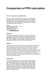
4.1 Selecting Hardware According to IEC 61511<br />
Having two standards to deal with in order to determine the system architecture does not<br />
make it easier for the end-user or system integrator. Many end-users and system integrators<br />
do not realize that even if they deal with the IEC 61511 standard that some subsystems of<br />
the safety functions still need to comply with the IEC 61508 standard. Figure 2 gives<br />
guidance. From this figure it becomes clear that we need per definition to follow IEC 61508 if<br />
we want to apply new hardware, which has not been developed yet. For any hardware<br />
which meets the IEC 61511 requirements for proven in use or has been assessed according<br />
to the requirements of IEC 61508 we can continue to follow the IEC 61511 requirements<br />
and particular Table 3 and 4. IEC 61511 defines proven in use as follows:<br />
“When a documented assessment has shown that there is appropriate evidence, based on<br />
the previous use of the component, that the component is suitable for use in a safety<br />
instrumented system”<br />
New hardware<br />
development?<br />
Follow<br />
IEC 61508-2<br />
Hardware<br />
Use hardware<br />
based on<br />
proven in use?<br />
Follow<br />
IEC 61511<br />
Use hardware<br />
developed<br />
and assessed<br />
according to<br />
IEC 61508?<br />
Follow<br />
IEC 61511<br />
Fig. 2. Which Standard to Follow: IEC 61508 or IEC 61511?<br />
Although proven in use is typically something that only an end-user can determine the<br />
suppliers of safety components will do everything to convince end-users and system<br />
integrators that their products are proven in use. The evidence though that needs to be<br />
delivered in order to “prove” proven in use is not so easy to accumulate:<br />
� Manufacturers quality, management and configuration management systems<br />
� Restricted functionality<br />
� Identification and specification of the components or subsystems<br />
� Performance of the components or subsystems in similar operating profiles and<br />
physical environments<br />
� The volume of the operating experience<br />
� Statistical evidence that the claimed failure rate is sufficiently low<br />
HIMA <strong>Functional</strong> <strong>Safety</strong> Consulting Services Page 13
White Paper<br />
Tino Vande Capelle, Dr. M.J.M. Houtermans<br />
<strong>Functional</strong> <strong>Safety</strong>: A Practical Approach<br />
for End-Users and System Integrators<br />
Especially the last point is very difficult to meet as failure track records are usually not<br />
available. End-user don’t always track them and product manufactures do not have the<br />
capability to track their products once they are sold and delivered.<br />
4.2 Certification and Third Party Reports<br />
End-users do not have the capabilities to verify for every single product that will be used in a<br />
safety function whether it meets the proven in use requirements of IEC 61511 or to assess<br />
them according to IEC 61508. Many end-users therefore make use of certified products or<br />
third party reports. There is a big difference between a product with a certificate and a<br />
product with a third party report.<br />
When a product is certified according to the IEC 61508 standard then this means that every<br />
single requirements of the standard is verified for this product. It is for example not possible<br />
to only certify the hardware of a programmable electronic system. Certification is allinclusive<br />
and thus also the software needs to be addressed. A well certified safety product<br />
not only addresses functional safety according to IEC 61508 but also issues like:<br />
� Electrical safety<br />
� Environmental safety<br />
� EMC/EMI<br />
� User documentation<br />
� Reliability analysis<br />
A certified product always comes with a certificate and a report to the certificate. The report<br />
to the certificate is very important as it explains how the verification or assessment has been<br />
carried out and whether there are any restrictions on the use of the product.<br />
A third party report is often used in industry but is only limited in scope. The report itself will<br />
outline what the scope of the analysis is. Many third party reports only focus on the<br />
hardware analysis of the product. In principle this is no problem as long as the end-user or<br />
system integrator is aware that other aspects of the product, like the software, also need to<br />
be addressed and may be another third party report should be requested that covers the<br />
software.<br />
4.3 Required hardware functional safety information<br />
For each safety device the end-user should assure themselves that the device is either<br />
compliant with IEC 61508 or with IEC 61511. Concerning the hardware the end-user should<br />
as a minimum ask from their suppliers the information listed in Table 6.<br />
HIMA <strong>Functional</strong> <strong>Safety</strong> Consulting Services Page 14
White Paper<br />
Tino Vande Capelle, Dr. M.J.M. Houtermans<br />
<strong>Functional</strong> <strong>Safety</strong>: A Practical Approach<br />
for End-Users and System Integrators<br />
Item<br />
Table 6 Hardware Checklist<br />
Applicable standard<br />
Type<br />
Hardware fault tolerance<br />
Safe failure fraction<br />
Safe detected failure rate<br />
Safe undetected failure rate<br />
Dangerous detected failure rate<br />
Dangerous undetected failure rate<br />
SIL level for which the product is fit for use<br />
Recommends periodic proof test interval<br />
With this information the end-user or system integrator can easily determine how to comply<br />
with the architectural constraints tables and build the architecture of their loop as desired.<br />
This information can be delivered by the supplier itself, through a third party report or<br />
through a certification report. It is up to the end-user to decide what is actually required<br />
(read what can be trusted). The architecture needs to be redesigned until the architectural<br />
constraints requirements are met.<br />
5. THE ROLE OF RELIABILITY ANALYSIS<br />
Once the architectural system design of the safety loop complies with the architectural<br />
constraints tables the loop has met already one of the most important requirements of the<br />
standards. Another important requirement is the probability of failure on demand (PFD) or<br />
continuous mode (PFH) calculation. This is the probability that the safety function cannot be<br />
carried out upon demand from the process. It needs to be calculated for those processes<br />
where the expected demand is less than once per year. If a loop is used in a continuous<br />
mode then it is necessary to calculate the frequency of failure of this loop per hour. This is<br />
necessary as we now are in a different situation. Where the demand loop can only cause a<br />
problem when there is an actual demand from the process the continuous loop can actual<br />
be the cause of a process upset when the loop itself has failed. Table 7 gives an overview of<br />
the required probabilities and frequencies per SIL level.<br />
Table 7 PFD versus PFH<br />
Demand Mode Continuous Mode<br />
SIL Probability of failure on demand Frequency of the failure per hour<br />
4 ≥ 10 -5 to < 10 -4 ≥ 10 -9 to < 10 -8<br />
3 ≥ 10 -4 to < 10 -3 ≥ 10 -8 to < 10 -7<br />
2 ≥ 10 -3 to < 10 -2 ≥ 10 -7 to < 10 -6<br />
1 ≥ 10 -2 to < 10 -1 ≥ 10 -6 to < 10 -5<br />
HIMA <strong>Functional</strong> <strong>Safety</strong> Consulting Services Page 15
White Paper<br />
Tino Vande Capelle, Dr. M.J.M. Houtermans<br />
<strong>Functional</strong> <strong>Safety</strong>: A Practical Approach<br />
for End-Users and System Integrators<br />
In order to carry out a probability or frequency calculation the following information is<br />
required:<br />
� A reliability model per loop<br />
� The reliability data for all equipment in the loop<br />
5.1 Reliability modeling<br />
A reliability model needs to be created for each loop of the safety system. There are<br />
different techniques available in the world to create reliability models. Well known<br />
techniques include:<br />
� Reliability block diagrams<br />
� Fault tree analysis<br />
� Markov analysis<br />
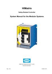
The reliability block diagram technique is probably one of the simplest methods available. A<br />
block diagram is a graphical representation of the required functionality. The block diagram<br />
of the safety function of Figure 1 is given in Figure 3 below. A reliability block diagram is<br />
always read from left to right where each block represents a piece of the available success<br />
path(s). As long as a block has not failed it is possible to go from left to right. Depending on<br />
build-in redundancy it is possible that alternative paths exist in the block diagram to go from<br />
left to right. Once the block diagram is created it is possible to use simple probability theory<br />
to calculate the probability of failure.<br />
T1<br />
T2<br />
TM 1<br />
TM 2<br />
I1<br />
I2<br />
CC CPU<br />
CC O1 O2 O3 R1<br />
R2 SOV ESD SV<br />
Fig. 3. Block diagram safety function<br />
Another technique is fault tree analysis (FTA). FTA is a technique that originates from the<br />
nuclear industry. Although the technique is more suitable to analysis complete facilities it is<br />
also used to calculate the probability of failure on demand of safety loops. A FTA is created<br />
with a top even in mind, e.g., safety does not actuate on demand. From this top event an<br />
investigation is started to determine the root causes. Basically an FTA is a graphical<br />
representation of combinations of basic events that can lead to the top event. A simplified<br />
version of the FTA for the safety function in Figure 1 is given in Figure 4. It is possible to<br />
quantify the FTA and calculate the probability of occurrence of the top even when the<br />
probabilities of occurrence of the basic events are known.<br />
HIMA <strong>Functional</strong> <strong>Safety</strong> Consulting Services Page 16
White Paper<br />
Tino Vande Capelle, Dr. M.J.M. Houtermans<br />
<strong>Functional</strong> <strong>Safety</strong>: A Practical Approach<br />
for End-Users and System Integrators<br />
Path 1 Failed<br />
T1 Tm1 I1<br />
Path 2 Failed<br />
T2 Tm2 I2<br />
<strong>Safety</strong> Function Failed<br />
Input Failed Logic Failed<br />
CC CPU CC O1 O2 O3<br />
Fig. 4. Simplified fault tree diagram safety function<br />
Output Failed<br />
SOV Drain R1 R2 R3<br />
Valve<br />
Research has indicated that Markov analysis is the most complete and suitable technique<br />
for safety calculations. Markov is a technique that captures transitions between two unique<br />
states. In terms of safety this means the working state and the failed state. Going from one<br />
state to the other can either be caused by a failure of a component or by repair of a<br />
component. Therefore a Markov model is also called a state transition diagram. See Figure<br />
5 for the Markov model of the safety function of Figure 1. Once the Markov model is created<br />
and the rate of transition is known between two states (that is the failure rate or repair rate) it<br />
is possible to solve the Markov model and calculate the probability of being in a state.<br />
OK<br />
Path 1<br />
Failed<br />
Path 2<br />
Failed<br />
Fig. 5. Markov model safety function<br />
System<br />
Failed<br />
HIMA <strong>Functional</strong> <strong>Safety</strong> Consulting Services Page 17
White Paper<br />
Tino Vande Capelle, Dr. M.J.M. Houtermans<br />
<strong>Functional</strong> <strong>Safety</strong>: A Practical Approach<br />
for End-Users and System Integrators<br />
The IEC 61508 standard also has standard formulas to calculate the PFD and PFH for each<br />
loop. These formulas are called simplified equations. What many people do not realize<br />
though is that these simplified equations are derived from Markov models and that in<br />
practice it is not so simple to derive them. Another limitation of these equations is that they<br />
only exist for 1oo1, 1oo2, 2oo2, 1oo2D, and 2oo3 architectures. For any other kind of<br />
architecture the standards do not provide equations and thus one needs to refer to any of<br />
the above mentioned techniques. Also the simplified equations are not flexible enough to<br />
handle diverse equipment, or different repair times and periodic proof test intervals. Hence<br />
their name simplified. For a complete list of simplified equations derived from Markov<br />
models see Börcsök (2004). The following two equations are examples of the simplified<br />
equations as they can be found in the standards<br />
PFD<br />
avg<br />
=<br />
1oo1 PFD equations:<br />
avg<br />
( λdu<br />
+ dd ) tCE<br />
PFD = λ ⋅<br />
2<br />
1oo2 PFD equations:<br />
( ( 1−<br />
β ) λ + ( 1−<br />
β ) λ )<br />
+ β<br />
D<br />
λ<br />
dd<br />
D<br />
dd<br />
⎛ T1<br />
⎞<br />
MTTR + βλdu<br />
⎜ + MTTR⎟<br />
⎝ 2 ⎠<br />
Rouvroye (1998) has compared different reliability techniques and their usefulness in the<br />
safety industry. Figure 6 gives an overview of these techniques and the result is that Markov<br />
analysis is the most complete technique. With Markov it is possible to create one model that<br />
allows us to take into account any kind of component, diverse component, different repair<br />
and test strategies. It is possible to calculate the probability of failure on demand, the rate<br />
per hour or the probability that the safety system causes a spurious trip. No other technique<br />
can do this.<br />
Expert analysis<br />
FMEA<br />
FTA<br />
Reliability Block<br />
Diagram<br />
Parts Count<br />
Analysis<br />
Markov Analysis<br />
<strong>Safety</strong> ranking Availability Probability of Effects of Trip rate<br />
comparison prediction Unsafe Failure test & repair prediction<br />
HIMA <strong>Functional</strong> <strong>Safety</strong> Consulting Services Page 18<br />
du<br />
2<br />
t<br />
CE<br />
t<br />
GE<br />
Time dependent<br />
effects<br />
Fig. 6. Comparison reliability techniques for safety analysis (Rouvroye, 1998)
White Paper<br />
Tino Vande Capelle, Dr. M.J.M. Houtermans<br />
<strong>Functional</strong> <strong>Safety</strong>: A Practical Approach<br />
for End-Users and System Integrators<br />
5.2 Reliability data<br />
Every reliability model needs reliability data in order to actually perform the reliability<br />
calculation and quantify the results. There are many sources for reliability data. The<br />
following list is an overview of available data:<br />
� End user maintenance records<br />
� Databases<br />
� Handbooks<br />
� Manufacturer data<br />
� <strong>Functional</strong> safety data sheets<br />
� Documented reliability studies<br />
� Published papers<br />
� Expert opinions<br />
� Reliability Standards<br />
The absolute best data an end-user can use is its own maintenance data. Unfortunately not<br />
many end-users have their one reliability data collection program and there is of course<br />
always the problem that a new safety system contains devices that were not used before by<br />
the end-user. Luckily there are more and more databases available were there is a<br />
collection of data from different sources which can be used by end-users.<br />
For the calculation we need the following reliability data for each device:<br />
� Safe detected failure rate<br />
� Safe undetected failure rate<br />
� Dangerous detected failure rate<br />
� Dangerous undetected failure rate<br />
This data was already collected when the architectural constraints were verified, see Table<br />
5. On plant level we also need to know the following reliability data:<br />
� Repair rate per device<br />
� Periodic proof test interval<br />
� Common cause<br />
The repair rate per device depends on the availability of the spare device and the availability<br />
of a repair crew. Periodic proof test intervals can be determined by three means:<br />
� The supplier of the device specifies a rate<br />
� Laws or standards determine a minimum inspection interval<br />
� The desired SIL level determines the period proof test interval through the PFD<br />
calculation<br />
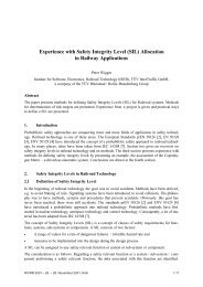
Once the reliability model is created and the reliability data is collected the actual calculation<br />
can be performed. Figure 7 shows an example of PFD calculation with and without periodic<br />
proof testing. Actually every year an imperfect proof test is performed which assures that the<br />
PFD level of the safety function stays within the SIL 3 range.<br />
HIMA <strong>Functional</strong> <strong>Safety</strong> Consulting Services Page 19
White Paper<br />
Tino Vande Capelle, Dr. M.J.M. Houtermans<br />
<strong>Functional</strong> <strong>Safety</strong>: A Practical Approach<br />
for End-Users and System Integrators<br />
probability to fail dangerous<br />
0.01<br />
0.001<br />
0.0001<br />
1e-005<br />
6. CONCLUSIONS<br />
Cracker <strong>Safety</strong> Loop 1<br />
without prooftest<br />
with proof test<br />
0 8760 17520 26280 35040 43800<br />
hours<br />
52560 61320 70080 78840 87600<br />
Fig. 7. Example PFD calculation with and without proof testing<br />
This purpose of the paper was to explain to end-users the most important high level<br />
requirements when designing safety instrumented system. The paper explained that safety<br />
system can fail in three different ways and that it is important to design, operate and<br />
maintain a safety system in a why that those three failures types are controlled. In order to<br />
understand the functional requirements of a safety system it is important to carry out hazard<br />
and risk analysis. The paper explained several techniques that can be used for this purpose.<br />
The results of the hazard and risk analysis are documented as the safety function<br />
requirement specification. Next the paper explained from a top level safety function<br />
description the high level requirements that end-users or system integrators need to follow<br />
in order to design the actual safety instrumented systems. The paper explained the<br />
significance of the architectural constraints from the point of view of the IEC 61508 and IEC<br />
61511 standard. For end-users and system integrators it is important to collect reliability<br />
data and to perform reliability analysis and be able to calculate the safe failure fraction and<br />
the probability of a failure on demand calculations.<br />
HIMA <strong>Functional</strong> <strong>Safety</strong> Consulting Services Page 20
White Paper<br />
Tino Vande Capelle, Dr. M.J.M. Houtermans<br />
<strong>Functional</strong> <strong>Safety</strong>: A Practical Approach<br />
for End-Users and System Integrators<br />
References:<br />
[1] Rouvroye, J.L., Houtermans, M.J.M., Brombacher, A.C., (1997). Systematic Failures in<br />
<strong>Safety</strong> Systems: Some observations on the ISA-S84 standard. ISA-TECH 97,ISA,<br />
Research Triangle Park, USA.<br />
[2] IEC (1999). <strong>Functional</strong> safety of electrical, electronic, programmable electronic safetyrelated<br />
systems, IEC 61508. IEC, Geneva.<br />
[3] IEC (2003). <strong>Functional</strong> safety – safety instrumented systems for the process industry,<br />
IEC 61511. IEC, Geneva.<br />
[4] Houtermans M.J.M., Velten-Philipp, W., (2005). The Effect of Diagnostics and Periodic<br />
Proof Testing on <strong>Safety</strong>-Related Systems, TUV Symposium, Cleveland, OHIO.<br />
[5] Börcsök, J., Electronic <strong>Safety</strong> Systems, Hardware Concepts, Models, and Calculations,<br />
ISBN 3-7785-2944-7, Heidelberg, Germany, 2004<br />
HIMA <strong>Functional</strong> <strong>Safety</strong> Consulting Services Page 21