

EEAC310A - Dual-3412 - Snap-on Equipment
EEAC310A - Dual-3412 - Snap-on Equipment
EEAC310A - Dual-3412 - Snap-on Equipment

Create successful ePaper yourself
Turn your PDF publications into a flip-book with our unique Google optimized e-Paper software.
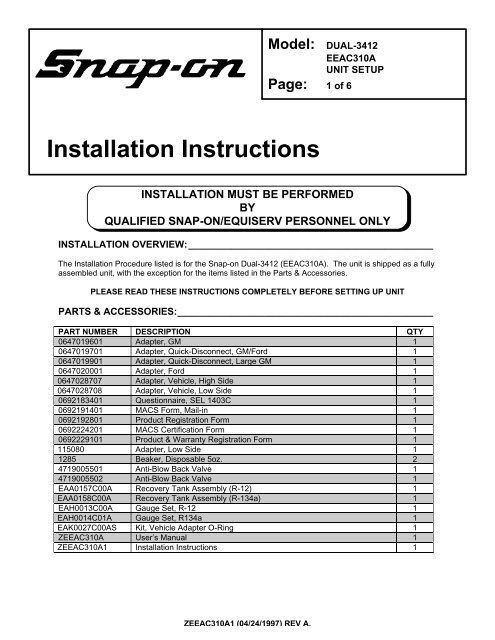
Model:Page: 1 of 6DUAL-<str<strong>on</strong>g>3412</str<strong>on</strong>g><str<strong>on</strong>g>EEAC310A</str<strong>on</strong>g>UNIT SETUPInstallati<strong>on</strong> Instructi<strong>on</strong>sINSTALLATION MUST BE PERFORMEDBYQUALIFIED SNAP-ON/EQUISERV PERSONNEL ONLYINSTALLATION OVERVIEW:_____________________________________________The Installati<strong>on</strong> Procedure listed is for the <str<strong>on</strong>g>Snap</str<strong>on</strong>g>-<strong>on</strong> <str<strong>on</strong>g>Dual</str<strong>on</strong>g>-<str<strong>on</strong>g>3412</str<strong>on</strong>g> (<str<strong>on</strong>g>EEAC310A</str<strong>on</strong>g>). The unit is shipped as a fullyassembled unit, with the excepti<strong>on</strong> for the items listed in the Parts & Accessories.PLEASE READ THESE INSTRUCTIONS COMPLETELY BEFORE SETTING UP UNITPARTS & ACCESSORIES:_______________________________________________PART NUMBER DESCRIPTION QTY0647019601 Adapter, GM 10647019701 Adapter, Quick-Disc<strong>on</strong>nect, GM/Ford 10647019901 Adapter, Quick-Disc<strong>on</strong>nect, Large GM 10647020001 Adapter, Ford 10647028707 Adapter, Vehicle, High Side 10647028708 Adapter, Vehicle, Low Side 10692183401 Questi<strong>on</strong>naire, SEL 1403C 10692191401 MACS Form, Mail-in 10692192801 Product Registrati<strong>on</strong> Form 10692224201 MACS Certificati<strong>on</strong> Form 10692229101 Product & Warranty Registrati<strong>on</strong> Form 1115080 Adapter, Low Side 11285 Beaker, Disposable 5oz. 24719005501 Anti-Blow Back Valve 14719005502 Anti-Blow Back Valve 1EAA0157C00A Recovery Tank Assembly (R-12) 1EAA0158C00A Recovery Tank Assembly (R-134a) 1EAH0013C00A Gauge Set, R-12 1EAH0014C01A Gauge Set, R134a 1EAK0027C00AS Kit, Vehicle Adapter O-Ring 1Z<str<strong>on</strong>g>EEAC310A</str<strong>on</strong>g> User’s Manual 1Z<str<strong>on</strong>g>EEAC310A</str<strong>on</strong>g>1 Installati<strong>on</strong> Instructi<strong>on</strong>s 1Z<str<strong>on</strong>g>EEAC310A</str<strong>on</strong>g>1 (04/24/1997) REV A.
Page 2 of 6REQUIRED TOOLS: ____________________________________________________• Safety Goggles (0001-5005)• Refrigerant Oil (Mineral) or Superlube (0681-0193-02 or -03)• R-12 Virgin Tank (Supplied by Customer)• R-134a Virgin Tank (Supplied by Customer)!THIS UNIT MUST BE PLUGGED INTO A PROPER AC OUTLET FOR UNITTO OPERATE CORRECTLY. REFER TO THE UNIT ID PLATE LOCATEDON BACK OF UNIT. EXTENSION CORDS ARE NOT RECOMMENDED,BUT IF AN EXTENSION CORD MUST BE USED, USE A CORD THAT ISLESS THAN 50 FEET WITH A 16 AWG, OR ABOVE 50 FEET AND LESSTHAN 100 FEET WITH A 14 AWG.!USE STANDARD REFRIGERANT HANDLINGSAFETY PROCEDURES WHEN PERFORMING INSTALLATIONALWAYS WEAR SAFETY GOGGLES, DON’T SPILL OR TOUCH LIQUIDREFRIGERANT, AVOID FLAMES, AND EXCESSIVE HEAT. USE ONLY INWELL VENTILATED AREA.Z<str<strong>on</strong>g>EEAC310A</str<strong>on</strong>g>1 (04/24/1997) REV A.
Page 3 of 6INSTALLATION INSTRUCTIONS: _________________________________________1. Cut Straps (A), and slide the cart<strong>on</strong> (B) off thepallet (H).2. Remove the protective pad (C).3. Remove the packing tape (D).4. Remove the accessory & gauge set box (E).5. Remove the packing material (F) from unit.6. Remove the plastic bag (NOT SHOWN) fromunit.7. From <strong>on</strong>e side of the unit, carefully lean theunit upwards and pull out <strong>on</strong>e-half of thebottom foam runner assembly (H).8. Gently return the unit to the pallet (I). Lock thelocking caster to prevent the unit from rolling.9. From the other side of the unit, carefully leanthe unit upwards and pull out the other half ofthe bottom foam runner assembly (H).10. Gently return the unit to the pallet (I).11. Unlock the caster and gently roll the unit off thepallet.12. Inventory all items using the Parts & Accessories list and inspect for damage.AFIGURE 1 Unit PackageBCDEFGHIPARTS & ACCESSORIES SETUP FOR THE R-12 SIDE: _______________________1. Remove the Gauge Set Assembly (EAH0013C00A) from the gauge set box and place <strong>on</strong> <strong>on</strong>e ofthe gauge set brackets. (Brackets are part of side panels.)2. Remove the Blue and Red Hoses from the gauge set box and OIL the seals <strong>on</strong> each end.3. C<strong>on</strong>nect the open end of the Blue and Red Hoses to the Gauge Set respectively.4. Remove the Beaker (1285) and slide it in the slot under the oil drain valve.5. Place the four GM/FORD adapters in the upper compartment.6. Remove the User's Manual, MAC Form/Certificati<strong>on</strong>, Product Registrati<strong>on</strong> Form, and WarrantyRegistrati<strong>on</strong> from the box. Hand these items to the Owner or Manager.7. Remove Recovery Tank (EAA0157C00A) from its box. Remove cardboard wrap from RecoveryTank. Set <strong>on</strong> floor in fr<strong>on</strong>t of unit.PARTS & ACCESSORIES SETUP FOR THE R-134a SIDE: _____________________1. Remove the Gauge Set Assembly (EAH0014C01A) from the gauge set box and place <strong>on</strong> theother gauge set bracket.2. Remove the Blue and Red Hoses from the gauge set box and OIL the seals <strong>on</strong> each end.3. C<strong>on</strong>nect the open end of the Blue and Red Hoses to the Gauge Set respectively.4. Remove the sec<strong>on</strong>d Beaker (1285) and slide it in the slot under the oil drain valve.5. C<strong>on</strong>nect the Red and Blue adapters (0647028707 and 0647028708) to the Red and Blue Hosesfrom the Gauge Set respectively.6. Place the O-Ring Kit (EAK0027C00AS) and Adapter Fitting (115080) in the upper compartment.7. Remove Recovery Tank (EAA0158C00A) from its box. Remove cardboard wrap from RecoveryTank. Set <strong>on</strong> floor in fr<strong>on</strong>t of unit.Z<str<strong>on</strong>g>EEAC310A</str<strong>on</strong>g>1 (04/24/1997) REV A.
Page 4 of 6PREPARING NEW R-12 RECOVERY TANK: ________________________________1. Referring to FIGURE 2, open the BLUE valve <strong>on</strong>Recovery Tank to release ALL COMPRESSED AIR.2. Remove the Yellow Hose from the gauge set box. OILthe seals <strong>on</strong> each end of hose.3. Add the anti-blow back valve (4719005501) to the shortside of yellow hose.4. Attach open end of Yellow Hose to BLUE valve <strong>on</strong>Recovery Tank (Refer to FIGURE 2). Attach other endof Yellow Hose with the anti-blow back valve to theservice port <strong>on</strong> side of unit Marked R-12 Recycle.Open ball valve <strong>on</strong> yellow hose.5. Plug AC Cord to a 115VAC outlet. Turn compressorswitch to ON, and turn the 3-way valve to VACUUM.6. Pull a vacuum for about 15 minutes.7. Once completed, close Recovery Tank valve (BLUE).8. Turn the 3-way valve to OFF, then the compressor switch to OFF.FIGURE 2 RECOVERY TANK9. Remove Yellow Hose from Recovery Tank. Re-OIL seal <strong>on</strong> Yellow Hose and c<strong>on</strong>nect to centerport <strong>on</strong> Gauge Set.10. Referring to FIGURE 3, open the Recovery Tank access panel. Place Recovery Tank (D) <strong>on</strong>Scale (E). Tank fittings should face straight out the fr<strong>on</strong>t of unit.11. C<strong>on</strong>nect the Yellow Hose from the bottom of unit to the purge valve (A) shown in FIGURE 3 <strong>on</strong>top of the Recovery Tank. C<strong>on</strong>nect the Red and Blue Hose from the bottom of the unit to theRED & BLUE valve (B) respectively <strong>on</strong> the Recovery Tank.NOTE: To avoid scale error due to stresses by improper positi<strong>on</strong>ing of the Blue Hose, positi<strong>on</strong>the Blue Hose at a 3 o’clock angle coming from the Recovery Tank valve.12. Slide the Temperature Lead between the Velcro Strap (C) <strong>on</strong> the Recovery Tank. Ensure that thevelcro strap is 2” above the weld of the tank.AERIAL VIEWOF TANKABYELLOW HOSETEMP LEADBLUE HOSERED HOSEECDFIGURE 3 TANK INSTALLATIONZ<str<strong>on</strong>g>EEAC310A</str<strong>on</strong>g>1 (04/24/1997) REV A.
Page 5 of 6PREPARING NEW R-134a RECOVERY TANK: ______________________________1. Referring to FIGURE 4, open the BLUE valve <strong>on</strong>Recovery Tank to release ALL COMPRESSED AIR.2. Remove the Yellow Hose from the gauge set box. OILthe seals <strong>on</strong> each end of hose.3. Add the anti-blow back valve (4719005502) to the shortside of yellow hose.4. Attach open end of Yellow Hose to BLUE valve <strong>on</strong>Recovery Tank (Refer to FIGURE 4). Attach other endof Yellow Hose with the anti-blow back valve to theservice port <strong>on</strong> side of unit Marked R-134a Recycle.Open ball valve <strong>on</strong> yellow hose.5. Plug AC Cord to a 115VAC outlet. Turn compressorswitch to ON, and turn the 3-way valve to VACUUM.6. Pull a vacuum for about 15 minutes.7. Once completed, close Recovery Tank valve (BLUE).8. Turn the 3-way valve to OFF, then the compressor switch to OFF.FIGURE 4 RECOVERY TANK9. Remove Yellow Hose from Recovery Tank. Re-OIL seal <strong>on</strong> Yellow Hose and c<strong>on</strong>nect to centerport <strong>on</strong> Gauge Set.10. Referring to FIGURE 5, open the Recovery Tank access panel. Place Recovery Tank (D) <strong>on</strong>Scale (E). Tank fittings should face straight out the fr<strong>on</strong>t of unit.11. C<strong>on</strong>nect the Yellow Hose from the bottom of unit to the purge valve (A) shown in FIGURE 5 <strong>on</strong>top of the Recovery Tank. C<strong>on</strong>nect the Red and Blue Hose from the bottom of the unit to theRED & BLUE valve (B) respectively <strong>on</strong> the Recovery Tank.NOTE: To avoid scale error due to stresses by improper positi<strong>on</strong>ing of the Blue Hose, positi<strong>on</strong>the Blue Hose at a 3 o’clock angle coming from the Recovery Tank valve.12. Slide the Temperature Lead between the Velcro Strap (C) <strong>on</strong> the Recovery Tank. Ensure that thevelcro strap is 2” above the weld of the tank.AERIAL VIEWOF TANKABYELLOW HOSETEMP LEADBLUE HOSERED HOSEECDFIGURE 5 TANK INSTALLATIONZ<str<strong>on</strong>g>EEAC310A</str<strong>on</strong>g>1 (04/24/1997) REV A.
Page 6 of 6PRE-CHARGING RECOVERY TANKS: _____________________________________NOTE: THIS PROCEDURE IS USED TO SETUP THE UNIT FOR CHARGING. RECOVERY TANKSHOULD HAVE AT LEAST A 25” VACUUM. THIS PROCEDURE IS DONE WHEN RECOVERYTANK IS ON THE SCALENOTE: START THIS PROCEDURE WITH THE R-12 SIDE. DO NOT ATTEMPT TO PERFORM THISPROCEDURE ON BOTH TANKS AT THE SAME TIME.1. Be sure Recovery Tank valves (B) are closed. Referto FIGURE 6.2. Disc<strong>on</strong>nect the Red hose from the Recovery Tank.3. Disc<strong>on</strong>nect and Re-Oil both the seals <strong>on</strong> Yellowhose (C). C<strong>on</strong>nect the l<strong>on</strong>g side of the Yellow Hoseto the Virgin Tank (A).4. C<strong>on</strong>nect the short side of the Yellow Hose to the RedValve <strong>on</strong> the Recovery Tank (B).5. Open the Red Valve <strong>on</strong> the Recovery Tank.6. Raise the Virgin Tank to a higher level than theRecovery Tank. Invert the Virgin Tank (A) and openvalve.A7. Open Hand Valve (D) <strong>on</strong> the Yellow Hose to allowthe refrigerant to flow. Gravity and vacuum willtransfer the liquid refrigerant to the Recovery Tankfaster than reclaiming it.8. Refer to the LCD Display to view the amount ofrefrigerant that has been transferred.9. After the desired amount of refrigerant has beentransferred, close valves <strong>on</strong> Virgin Tank andRecovery Tank. Set Virgin Tank <strong>on</strong> ground upright.DC10. Close Hand Valve <strong>on</strong> Yellow Hose. Disc<strong>on</strong>nectYellow Hose from Recovery Tank.B11. Re-Oil seals <strong>on</strong> anti-blow back valve <strong>on</strong> the RedHose from unit and c<strong>on</strong>nect to Recovery Tank.Open Recovery Tank valve (RED).12. Re-Oil seal <strong>on</strong> Yellow Hose and c<strong>on</strong>nect to serviceport <strong>on</strong> side of unit Marked Recycle. Open Hand Valve <strong>on</strong> Yellow Hose.13. Plug the unit into a 115VAC outlet. Turn the compressor switch to ON, and the 3-way valve toRECYCLE. This will reclaim the refrigerant from the hose. (Opti<strong>on</strong>al: Opening Virgin Tank valvewill recover the rest of the refrigerant.)14. Once complete, turn the 3-way valve and compressor switch to OFF. Disc<strong>on</strong>nect Yellow Hosefrom Virgin Tank.15. Re-Oil seals <strong>on</strong> Yellow Hose and c<strong>on</strong>nect to center port <strong>on</strong> Gauge Set.FIGURE 6 CHARGING TANKREPEAT THE “PRE-CHARGING RECOVERY TANKS” FOR OTHER RECOVERY TANK!REMEMBER TO OIL O-RINGS AND SEALSWHEN ATTACHING HOSES OR FITTINGSINSTALLATION COMPLETE/SETUP COMPLETEZ<str<strong>on</strong>g>EEAC310A</str<strong>on</strong>g>1 (04/24/1997) REV A.


