Integrating Spheres theory and applications - Allied Scientific Pro
Integrating Spheres theory and applications - Allied Scientific Pro
Integrating Spheres theory and applications - Allied Scientific Pro

You also want an ePaper? Increase the reach of your titles
YUMPU automatically turns print PDFs into web optimized ePapers that Google loves.
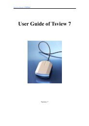
<strong>Integrating</strong> Sphere Theory <strong>and</strong> Applications1.2.1 The Sphere MultiplierEquation 12 is purposely divided into two parts. The firstpart is approximately equal to Eq. 5, the radiance of a diffusesurface. The second part of the equation is a unitlessquantity which can be referred to as the sphere multiplier.EQ. 131.2.2 The Average ReflectanceThe sphere multiplier in Eq. 13 is specific to the case wherethe incident flux impinges on the sphere wall, the wall reflectanceis uniform <strong>and</strong> the reflectance of all port areas is zero.The general expression is:EQ. 14It accounts for the increase in radiance due to multiple reflections.The following chart illustrates the magnitude of thesphere multiplier, M, <strong>and</strong> its strong dependence on both theport fraction, f, <strong>and</strong> the sphere surface reflectance r.where; r 0= the initial reflectance for incident fluxr w= the reflectance of the sphere wallr i= the reflectance of port opening if i= the fractional port area of port opening iThe quantitycan also be described asthe average reflectance r for the entire integrating sphere.Therefore, the sphere multiplier can be rewritten in terms ofboth the initial <strong>and</strong> average reflectance:EQ. 15FIGURE 4A simplified intuitive approach to predicting a flux densityinside the integrating sphere might be to simply divide theinput flux by the total surface area of the sphere. However,the effect of the sphere multiplier is that the radiance of anintegrating sphere is at least an order of magnitude greaterthan this simple intuitive approach. A h<strong>and</strong>y rule of thumb isthat for most real integrating spheres (.94
<strong>Integrating</strong> Sphere Theory <strong>and</strong> ApplicationsThe radiance produced after only n reflections can be comparedto the steady state condition.where the time constant, t, is calculated as:EQ. 18<strong>and</strong>r = the average wall reflectancec = the velocity of lightD s= the diameter of the integrating sphereTime constants of typical integrating spheres range from afew nanoseconds to a few tens of nanoseconds.FIGURE 5Since the integrating sphere is most often used in thesteady state condition, a greater number of reflectionsproduces the steady state radiance as both r increases <strong>and</strong>f decreases. Therefore, integrating sphere designs shouldattempt to optimize both parameters for the best spatialintegration of radiant flux.1.4 Temporal Response of an <strong>Integrating</strong> SphereMost integrating spheres are used as steady state devices.The previous analysis of their performance <strong>and</strong> applicationassumes that the light levels within the sphere havebeen constant for a long enough time so that all transientresponse has disappeared. If rapidly varying light signals,such as short pulses or those modulated at high (radio)frequencies, are introduced into an integrating sphere, theoutput signal may be noticeably distorted by the “pulsestretching” caused by the multiple diffuse reflections. Theshape of the output signal is determined by convolving theinput signal with the impulse response of the integratingsphere.This impulse response is of the form:EQ. 175
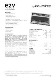
<strong>Integrating</strong> Sphere Theory <strong>and</strong> Applications2.0 <strong>Integrating</strong> Sphere DesignThe design of an integrating sphere for any applicationinvolves a few basic parameters. This includes selecting theoptimum sphere diameter based on the number <strong>and</strong> size ofport openings <strong>and</strong> peripheral devices. Selecting the propersphere coating considers spectral range as well as performancerequirements. The use of baffles with respect toincident radiation <strong>and</strong> detector field-of-view is discussed;<strong>and</strong> radiometric equations are presented for determining thecoupling efficiency of an integrating sphere to a detectionsystem.2.1 <strong>Integrating</strong> Sphere DiameterFigure 4 indicates that decreasing the port fraction has adramatic effect on increasing the sphere multiplier. For portfractions larger than 0.05, one begins to lose the advantageoffered by the high reflectance coatings available forintegrating spheres. The first rule of thumb for integratingspheres is that no more than 5% of the sphere surface areabe consumed by port openings.Real integrating spheres are designed by initially consideringthe diameter required for the port openings. Portdiameter is driven by both the size of devices as well as thegeometrical constraints required by a sphere system.Consider the case of a two port integrating sphere; bothports are of unit diameter. The relative radiance producedas a function of sphere diameter, Ds , for an equivalent inputflux is proportional to:EQ. 19FIGURE 6The smallest sphere produces the highest radiance ingeneral. However, since the integrating sphere is usuallyemployed for its ability to spatially integrate input flux, alarger sphere diameter <strong>and</strong> smaller port fraction will improvethe spatial performance. Notice in Figure 6 that all threesphere designs converge on the same unit flux densityas the reflectance approaches 1.0. Therefore, high reflectanceintegrating sphere materials such as Spectralon canoptimize spatial performance at only a slight tradeoff inradiance efficiency.2.2 <strong>Integrating</strong> Sphere Coating SelectionThe sphere multiplier as illustrated by Figure 4 is extremelysensitive to the sphere surface reflectance. Therefore, theselection of sphere coating or material can make a large differencein the radiance produced for a given sphere design.Consider the diffuse reflectors offered by Labsphere ASP knownas Spectraflect <strong>and</strong> Spectralon. Both are useful for UV-VIS-NIR <strong>applications</strong> in the 250 nm to 2500 nmspectral region. The typical spectral reflectance of each isshown in Figure 7 below.The equation can be plotted as a function of reflectance fordifferent sphere diameters <strong>and</strong> the resulting port fraction foreach is shown in Figure 6.FIGURE 76
<strong>Integrating</strong> Sphere Theory <strong>and</strong> ApplicationsBoth coatings are highly reflective, over 95% from 350 nm to1350 nm, therefore, intuitively one might expect no significantincrease in radiance for the same integrating sphere.However, the relative increase in radiance is greater thanthe relative increase in reflectance by a factor equal to thenewsphere multiplier, M new.EQ. 20The magnitude of this effect is depicted below:FIGURE 9Baffles can be considered extensions of the sphere surface.Their contribution to the sphere area can be factored intothe radiance equation although it is not usually significant.The fractional contribution of baffles to the sphere surfacearea is usually quite small.The radiance at the incident area, Li, is higher than the averagefor the entire sphere surface by an amount equal to Eq.5 for the directly irradiated area Ai. The radiance ratio for theincident to average sphere radiance is given by:EQ. 21FIGURE 8Although Spectralon offers a 2% to 15% increase in reflectanceover Spectraflect within the wavelength range, anidentical integrating sphere design would offer 40% to 240%increased radiance. The largest increase occurs in the NIRspectral region above 1400 nm.2.3 Baffles <strong>and</strong> Detector Field-of-Viewwhere f i= A i/A s.The radiance ratio increases rapidly with decreasing spotdiameter. Considering the reciprocity of light rays, the sameconsiderations must be applied to the field-of-view of a photodetectorwithin the integrating sphere. The fractional areaf ican be converted into the detector’s angular field-of-view.In using integrating spheres, it is important that the viewedradiance does not include a portion of the sphere surfacedirectly irradiated by incident flux. This will introduce a falseresponse.Baffles coated with the same material as the integratingsphere wall block the view of incident flux which has notundergone at least two reflections from the sphere surface.The optical system in Figure 9 cannot directly view the incidentflux. However, the baffle is positioned to prevent firstreflections from entering the field-of-view for thephotodetector.FIGURE 107
<strong>Integrating</strong> Sphere Theory <strong>and</strong> ApplicationsIn both cases, as either the area of irradiation or the fieldof-viewapproaches total coverage of the sphere surface,the radiance ratio approaches unity. As either parameter decreases,the radiance ratio rapidly increases. In <strong>applications</strong>where the port of an integrating sphere is being used as auniform radiance source, the result is increased non-uniformity.When the sphere is used as a collector to measureradiant flux, the result is increased measurement error ifincident flux directly enters the detector’s field-of-view.2.4 Flux on the PhotodetectorThe radiance of the sphere wall determines the total fluxincident on a photodetector mounted at or near a port of theintegrating sphere.One method of providing a photodetector with a hemisphericalfield-of-view is to attach a diffuser. One of the bestdiffuser attachments is an auxiliary or satellite integratingsphere. The port of this sphere is baffled from direct view ofincident flux.FIGURE 12By definition, the total flux incident on the detector activearea, A d(m 2 ) is:EQ. 22FIGURE 11Of course, Figure 9 (on the previous page) presents anothersolution to the potential problem of small detector field-ofview.In this case, the real field-of-view on the sphere wallas defined by the photodetector’s imaging system can beconsidered as a “virtual detector” with a hemisphericalfield-of-view. The baffle placement ensures this effect. Theintegrating sphere <strong>applications</strong> shown in Section 3.0 presentother examples of proper baffle placement.where: W = projected solid angle (sr)A good approximation for W in almost all cases is:EQ. 23In the case of imaging optics used with the detector, theangle q is subtended from the exit pupil of the system. Thedetector is the field stop of the system.FIGURE 138
<strong>Integrating</strong> Sphere Theory <strong>and</strong> ApplicationsThe f-number (f/#) of an optical system is also used toexpress its light gathering power. Therefore:EQ. 24Reflectance losses at the air/fiber interface must be consideredin determining the total flux accepted by the fiber. If Ris the reflectance at the fiber face, then:EQ. 27The efficiency of the optical system, which is generally afunction of the transmittance <strong>and</strong> reflectance of individualcomponents, must also be considered. Therefore the detectorincident flux is:EQ. 25For a single str<strong>and</strong> fiber, A fis the area of the fiber endcalculated for the core diameter. If a fiber bundle is used,this quantity becomes the individual core diameter timesthe number of fibers in the bundle. The light emanating fromthe other end of the fiber is a function of its length (cm), thematerial extinction coefficient (cm -1 ), <strong>and</strong> the exitinterface reflection.where, e 0= optical system efficiency (unitless).2.5 Fiberoptic CouplingA similar equation is used to calculate the incident flux gatheredby a fiberoptic cable coupled to an integrating sphere.FIGURE 14The numerical aperture (NA) of an optical fiber is used todescribe its light coupling ability. The projected solid angleis:EQ. 269
<strong>Integrating</strong> Sphere Theory <strong>and</strong> Applications3.0 <strong>Integrating</strong> Sphere Applications<strong>Integrating</strong> spheres collect <strong>and</strong> spatially integrate radantflux. The flux can be measured directly or after it hasinteracted with a material sample. The sphere as part ofa radiometer or photometer can directly measure the fluxoriginating from lamps <strong>and</strong> lasers or the flux density producedfrom hemispherical illumination. Perhaps the largestapplication for integrating spheres is in the measurement ofthe total reflectance or transmittance from diffuse or scatteringmaterials. An alternative application utilizes the portopening of an internally illuminated integrating sphere asa large area source that features uniform radiance. Thesesources can be used to calibrate electronic imaging devices<strong>and</strong> systems or simply as uniform back illuminators.3.1 Radiometers <strong>and</strong> PhotometersAn integrating sphere combined with a photodetector of theappropriate spectral response can be used to directly measurethe total geometric flux emanating from a light sourceor the flux density of an illuminated area. The geometricdistribution of the light to be measured determines the appropriateintegrating sphere design. The spectral propertiesof the light source determines the appropriate photodetectionsystem.In general, radiometers measure light in accordance withthe SI unit of radiant flux, the watt. Quantum response photodetectorsare most commonly used in radiometers. Sincetheir responsivity varies spectrally, it is more appropriate totailor the response for a specific spectral region through theuse of optical filters in nearly all cases except perhaps whenthe incident flux is monochromatic.Thermal detectors respond equally to all wavelengthsof light. This property also makes them susceptible tobackground thermal radiation. Most often, they need to betemperature controlled <strong>and</strong> the input radiation is modulatedfor synchronous detection.Spectroradiometers measure light as a function of wavelength.These feature a detector coupled to a spectral separationdevice such as a diffraction grating monochromator ora Fourier transform interferometer.The spectral dependence of the integrating sphere multipliermodifies the relative spectral responsivity of the photodetector.The sphere/detector combination must be consideredmutually in order to design or calibrate the measurementsystem for a particular responsivity.Photometers are a distinct type of radiometer which use aquantum detector filtered to emulate the spectral responseof the st<strong>and</strong>ard human observer. This specific responsivityis known as the luminous efficiency function. The primaryunit of photometric flux is the lumen. The detector responsefunction weights <strong>and</strong> integrates the spectral radiant flux toproduce the lumen scale. Photometry has the uniquedistinction of being the only system of physical measurementbased entirely on human perception.3.1.1 The Sphere PhotometerThe oldest application for the integrating sphere is themeasurement of total geometric luminous flux from electriclamps. The technique originated at the turn of the 20th centuryas a simple <strong>and</strong> fast method of comparing the lumenoutput of different lamp types. It is still widely used in thelamp industry for manufacturing quality control. Thealternative method is a goniophotometer which would needto rotate a photodetector in a complete sphere around thelamp. Each discrete intensity point (lm/sr) is then integratedover 4p steradians.FIGURE 15In a sphere photometer, the lamp to be measured ismounted at the center of the integrating sphere <strong>and</strong> baffledfrom the viewing port equipped with a diffuser <strong>and</strong> photopicresponse detector. The baffle is usually positioned at 2/3of the radius from the sphere center. Its size should be assmall as possible yet large enough to screen the maximumdimension of the lamp.The lumen output from the test lamp is determined by firstcalibrating the photodetector signal using a lamp st<strong>and</strong>ardof known luminous flux. The lamps are alternately substitutedinto the integrating sphere. An auxiliary lamp can bepermanently mounted inside the sphere to correct for thesubstitution error caused by different self absorption fromthe test <strong>and</strong> st<strong>and</strong>ard lamps. Auxiliary lamps are10
<strong>Integrating</strong> Sphere Theory <strong>and</strong> ApplicationsIn either design, the angular response does not perfectlycorrespond to the cosine function since certain incident rayswill first impose on the baffle before being distributed to thesphere wall. The true angular response is usually determinedexperimentally <strong>and</strong> then applied as a correction factorin high accuracy irradiance measurements.3.2 Reflectance <strong>and</strong> Transmittance of MaterialsFIGURE 18The centrally located baffle prevents direct irradiation of thedetector. The entrance port becomes the effective measuringaperture of the device. For regular irradiance measurements,the cosine angular response is required. Theirradiance of a flat surface E, is proportional to the cosine ofthe angle of incidence, q.EQ. 28For spectral irradiance measurements in which a monochromatoris used, a 90° port geometry can be more accommodating.This design is commonly used for global irradiancemonitors since the integrating sphere provides good spectralresponse from the UV to the NIR regions of the atmosphericsolar spectrum. A quartz weather domeguards against environmental contaminants.The single largest application for integrating spheres is themeasurement of the reflectance <strong>and</strong> transmittance of diffuseor scattering materials. The measurements are almostalways performed spectrally, as a function of wavelength.The one exception may be the measurement of luminousreflectance or transmittance using a photopic responsedetector.In the ultraviolet, diffuse transmittance is used to determinethe UV resistance of pharmaceutical containers, sunprotective clothing, <strong>and</strong> automotive paints. In the visiblespectrum, the color of materials is quantified <strong>and</strong> controlledin industries such as paints, textiles <strong>and</strong> the graphic arts. Inthe infrared, the total hemispherical reflectance determinessurface emissivities applied to radiant heat transfer analysisof thermal control coatings <strong>and</strong> foils used in spacecraftdesign.A transmittance measurement places a material sample atthe entrance port to the sphere (as shown in Figure 20).FIGURE 20In reflectance measurements, the sample is placed at aport opening opposite the entrance port. The incident flux isreflected by the sample. The total hemispherical reflectance,both the diffuse <strong>and</strong> specular components, is collected bythe integrating sphere.FIGURE 1912
<strong>Integrating</strong> Sphere Theory <strong>and</strong> ApplicationsCalibration of the reflectance scale is performed by comparingthe incident flux remaining in the sphere after reflectingfrom a st<strong>and</strong>ard reference material.FIGURE 21The angle of incidence in reflectance measurements is usuallyslightly off normal up to 10°. The specular componentcan be excluded from the measurement by using normal(0°) incidence or by fitting another port in the specular path<strong>and</strong> using a black absorbing light trap to extinguish thespecular flux.Reflectance measurements at larger or variable incidentangles are performed by placing the sample at the center ofthe sphere <strong>and</strong> rotating it about a fixed input beam.Baffles are placed to prevent the photodetector on thesphere from directly viewing the irradiated sample in eithermeasurement. In the reflectance geometry, a baffle isusually placed between the portion of the sphere wall thatreceives the specular component as well. It is best to use aphotodetector with a hemispherical field-of-view to reduceany sensitivity to the scatter distribution function of thesample.3.2.1 Substitution vs. Comparison <strong>Spheres</strong>A unique integrating sphere error is attributed to the designsdepicted in Figure 20 <strong>and</strong> Figure 21 due to the sample effectivelyaltering the average reflectance of the sphere wall.Calibration of the transmittance scale is usually performedby initially measuring the incident flux before the sample isplaced against the entrance port.FIGURE 23The ideal measurement relationship is for the ratio of radianceproduced inside the sphere to be equal to the ratio ofthe reflectance for each material.where; r r= the reflectance of the reference materialEQ. 29The sample measurement quantity, r s, is properly knownas the reflectance factor. The term refers to the fact that theincident flux was not directly measured as the reference.However, in the substitution sphere of Figure 23, the averagereflectance of the sphere changes when the sample issubstituted for the reference material. The true measurementequation in a substitution sphere is, therefore;EQ. 30where; r s= average wall reflectance with sampler r= average wall reflectance with referenceFIGURE 22The average reflectance with the sample material in place,r s, cannot be easily determined since it is also dependenton r s. The magnitude of this error can be plotted for a typicalSpectraflect integrating sphere with 5% port openings<strong>and</strong> a 1% sample port opening. The reference material isSpectralon.13
<strong>Integrating</strong> Sphere Theory <strong>and</strong> Applications3.2.2 Measurement Geometry 0°/d vs. d/0°The previous examples of reflectance <strong>and</strong> transmittance geometriesdepicted a directional incident flux <strong>and</strong> hemisphericalcollection by the integrating sphere after interaction withthe sample material. The geometry is correctly defined asdirectional/hemispherical <strong>and</strong> commonly abbreviated as0°/d referring to near normal incidence <strong>and</strong> diffuse collection.The 0° angle should be replaced by the actual angleof incidence when describing a particular integrating sphereinstrument, for example, 8°/d. Reflectance factor is thequantity directly measured in 0°/d geometry.FIGURE 24In order to utilize Eq. 29, the proper sphere design is onethat keeps the average reflectance constant. A comparisonsphere mounts both the sample <strong>and</strong> the reference simultaneouslyto port openings in the integrating sphere.A reciprocal optical geometry can be used in both reflectance<strong>and</strong> transmittance measurements. In the d/0° geometry,the sample irradiation is hemispherical <strong>and</strong> the sampleis viewed from the near normal direction.FIGURE 26FIGURE 25The comparison sphere features an average sphere wallreflectance that is constant, a function of each materialreflectance. In a single beam instrument, the sphere can berotated to alternately position each material in the incidentbeam. In double beam reflectometers, a baseline is initiallyestablished with a st<strong>and</strong>ard reference material mounted atthe sample port opening in order to determine the ratio ofincident flux in each beam.The measurement quantity in the reflectance geometry isproperly termed the radiance factor. The radiance of thesample under diffuse irradiation is compared to the radianceof a reference material. The radiance factor is equivalentto the reflectance factor for reciprocal geometries, i.e.- theétendue <strong>and</strong> angle from the sample normal is the same forthe directional beams, a hemispherical detector field-of-view(0°/d) is replaced by a hemispherical input flux (d/0°). Instrumentswhich use d/0° often employ an auxiliary integratingsphere source.Substitution error also applies to transmittance measurementssince the sample surface tangential to the port openingwill contribute to the average reflectance of the spherecavity. A comparison sphere is recommended for transmittancemeasurements as well.14
<strong>Integrating</strong> Sphere Theory <strong>and</strong> Applicationsto increase the radiance as well as provide a step wisemethod of attenuating the radiance level.Tungsten halogen lamps are most commonly used withintegrating sphere sources. These lamps provide a continuousspectrum, free of emission lines or temporal instabilitywhen operated from a current regulated power supply. Thespectral radiance of the sphere source can be estimatedby combining the sphere radiance equation with blackbodyequations for the spectral radiant flux.There are two main advantages of the d/0° geometry. Theincident flux is significantly greater since integrating spheresprovide total light collection, thus increasing the signaltonoiseratio for the instrument. Polychromatic irradiationwill stimulate photon induced radiance, such as that due tofluorescence, which often needs to be quantified in manycolor <strong>and</strong> appearance measurements. The main disadvantageof d/0° instruments is sample heating which can inducethermochromic effects. Many commercial color measurementinstruments will utilize flashlamps to reduce thermalmeasurement error.3.3 Uniform SourcesFIGURE 27In the previous <strong>applications</strong>, the integrating sphere is usedas a collecting device for the measurement of radiant flux,either the absolute amount emitted from a light source itselfor the relative amount of flux transmitted or reflected bymaterials.The open port of an internally illuminated integrating spherecan itself serve as a large area diffuse light source.<strong>and</strong>,where;EQ. 31EQ. 32r(l) = spectral reflectance of sphere surfaceF i l= spectral radiant fluxF o= rated wattage of the lampl = wavelengthT = temperature of the filament≈ correlated color temperaturec 1, c 2, s = blackbody constantsThe radiance equation is multiplied by the number of lampsif more than one lamp is used.FIGURE 28Lamps are placed inside the integrating sphere around theperimeter of the viewing port. The lamps are usually baffledfrom the port. The radiance of the sphere is a function of thewattage rating of the lamp. Multiple lamps can be used15
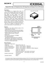
<strong>Integrating</strong> Sphere Theory <strong>and</strong> Applications3.3.1 Modifying the Source RadianceIf it is required to either modify the spectral radiance orprovide greater adjustability in radiance level, then the lampmust be placed externally to another port opening.3.3.2 Irradiance UniformityRadiance is the flux density leaving a radiant surface asviewed from a distance away from the surface. A Lambertiansurface features a radiance that is perfectly diffuse,independent of viewing angle. Irradiance is the flux densityfalling on a surface <strong>and</strong> is measured at the plane of thesurface.<strong>Integrating</strong> sphere sources are most often used to test animaging system. The desired effect is uniform radiancewithin the field-of-view of the system under test.FIGURE 29The incident radiant flux is modified by the efficiency of theoptics used. The centrally located baffle is recommended.Direct illumination through a side port would create areasof increased radiance. The field of view into the integratingsphere should be confined to the baffle. The sphere surfacesurrounding the baffle tends to be more brightly illuminated.If an optical filter is used to shape the spectral radiance,care should be taken to ensure that the focused light fromthe reflector does not damage the filter.When the field-of-view must be wider than the baffle willpermit, a diffuse input at an entrance port opening adjacentto the viewing port can be provided by an auxiliary integratingsphere.FIGURE 31The source can be used to back illuminate a printed oretched image such as photographic film for image digitizationor resolution targets for MTF testing. Radiance uniformityto within 1%-2% is ensured by using one of the threedesigns previously illustrated.It is sometimes desired to use the sphere source for testinga non-imaging device such as a CCD or similar arraydetector. In this case the desired effect is uniform irradiance.The device under test is often placed coaxial with, but atsome distance away from the port of the integrating spheresource. When used in this way, the two important quantitiesto be determined are the axial irradiance at the center of theobject as well as the irradiance at the off-axis edge.FIGURE 30In this case, the distance between spheres should be minimizedor the incident illumination becomes more directionalthan diffuse. The system in Figure 29 is more efficientthan the auxiliary sphere design for a single lamp. Multipleauxiliary sphere inputs can be considered to increase theradiance of the larger sphere.FIGURE 3216
In Figure 32, the axial illuminance, E ois given by:EQ. 32<strong>Integrating</strong> Sphere Theory <strong>and</strong> ApplicationsIn the examples illustrated Sfor a source diameter equal toor larger than the object, the cos4f law predicts the edge irradianceto within 1% for source to object distances at leasttwo times larger than the source diameter. At this distance,the uniformity is within 10%, however, the irradiance is lessthan 5% of the value at the plane of theport.Even for a perfectly Lambertian, perfectly uniform circularsource, the uniformity of the irradiance across a plane objectat a finite distance will vary with the off-axis angle f. Theuniformity fall off is given in Table 1 where both the distance<strong>and</strong> the dimension of the object are expressed as multiplesof the sphere port diameter, x/D <strong>and</strong> d/D respectively. Uniformityis defined as the ratio of the irradiance at the edge ofthe object to the axial irradiance, Ee/Eo.It is important to note that Table 1 <strong>and</strong> Figure 33 displaycalculated theoretical values of uniformity for the idealperfectly Lambertian source. Laboratory measurements ofreal integrating sphere sources correlate extremely well withthese predicted values. Therefore, the data provided can beused as design guidelines in choosing the correct uniformsource for a particular application.Examination of Table 1 reveals that the uniformity is 100%at the plane of the port. It decreases as the object is movedaway from the port for a short distance <strong>and</strong> improves as thedistance becomes sufficiently long. This phenomenon canbe illustrated graphically as shown in Figure 33.For small values of both q <strong>and</strong> f (
<strong>Integrating</strong> Sphere Theory <strong>and</strong> ApplicationsGUIDE TO OPTICAL UNITSPHOTOMETRIC QUANTITIES AND UNITSQuantity Symbol Units abbreviationsLuminous energy Q vLumen•second = talbot lm•s = talbotLuminous density U vLumen•second/m 3 lm•s/m 3Luminous flux F vLumen lmLuminous efficacy K lumen/watt lm W –1Luminous exitance M vlumen/m 2 lm m –2Luminance (brightness) L vc<strong>and</strong>ela/m 2 cd/m 2c<strong>and</strong>ela/p ft 2 = footlambert cd/p ft 2 = fLc<strong>and</strong>ela/p cm 2 = lambertcd/p cm 2 = LLuminous intensity I vc<strong>and</strong>ela cd (lm sr–1)Illuminance E vlumen/m 2 = lux lm/m 2 = lxlumen/ft 2 = footc<strong>and</strong>lelm/ft 2 = fcRADIOMETRIC QUANTITIES AND UNITSQuantity Symbol Units abbreviationsRadiant energy Q joule = watt–second J = W•sRadiant energy density U joule/m 3 J/m 3Radiant flux (power) F, P watts = joule/second W = J/sRadiant exitance M watts/m 2 W/m 2Radiance L watts/m 2 •steradian W/m 2 •srRadiant intensity I watts/steradian W/srIrradiance E watts/m 2 W/m 2SPECTRAL RESPONSE OF THE NORMAL HUMAN EYE WITH LUMINOUS TO RADIOMETRIC CONVERSIONWavelength CIE Photopic Photopic Wavelength CIE Photopic Photopic(nm) luminous Lumen/Watt (nm) luminous Lumen/Wattefficiency Conversion efficiency ConversionCoefficient Factor Coefficient Factor390 0.0001 0.13 570 0.9520 649.0400 0.0004 0.27 580 0.8700 593.0410 0.0012 0.82 590 0.7570 516.0420 0.0040 2.73 600 0.6310 430.0430 0.0116 7.91 610 0.5030 343.0440 0.0230 15.7 620 0.3810 260.0450 0.0380 25.9 630 0.2650 181.0460 0.0600 40.9 640 0.1750 119.0470 0.0910 62.1 650 0.1070 73.0480 0.1390 94.8 660 0.0610 41.4490 0.2080 142.0 670 0.0320 21.8500 0.3230 220.0 680 0.0170 11.6510 0.5030 343.0 690 0.0082 5.59520 0.7100 484.0 700 0.0041 2.78530 0.8620 588.0 710 0.0021 1.43540 0.9540 650.0 720 0.0010 0.716550 0.9950 679.0 730 0.0005 0.355555 1.0000 683.0 740 0.0003 0.170560 0.9950 679.0 750 0.0001 0.82018
<strong>Allied</strong> <strong>Scientific</strong> <strong>Pro</strong> (Headquarter)815 Boul. de la Carrière, bureau 202Gatineau, Québec, Canada, J8Y 6T4info@alliedscientificpro.com (General information)sales@alliedscientificpro.com (Request for quote)purchasing@alliedscientificpro.com (Send PO)Tel: 1-800-253-4107 USA <strong>and</strong> CanadaTel:+33-975181601 (France Europe)EXPERIENCE LABSPHERELIGHT MEASUREMENT. SENSOR CALIBRATION. MATERIALS & COATINGS. SPECTROSCOPY ACCESSORIES.Tel: 1-819-595-0338 poste 36 Canada (inside the CDET center)Fax: 1-(866) 526-4086<strong>Allied</strong> <strong>Scientific</strong> <strong>Pro</strong> (Asia)Unified Taiwan Business #:53011049PO Box 702F, N°307, Tun Hwa North Road, Taipei 105 231 Shaker StreetNorth Sutton, NH 03260USATAIWAN (R.O.C.), Asia10583 307info@alliedscientificpro.comTel: 886 (0)987117946 (Taiwan)PHONE: +1 (603) 927-4266For Malaysia, India <strong>and</strong> Singapore: singapour@alliedscientificpro.cFAX: +1 (603) 927-4694Tel: +65 83997121 (Singapore)labsphere@labsphere.comwww.labsphere.com