Nike Transmission Line Design - icon.co.za
Nike Transmission Line Design - icon.co.za
Nike Transmission Line Design - icon.co.za

Create successful ePaper yourself
Turn your PDF publications into a flip-book with our unique Google optimized e-Paper software.
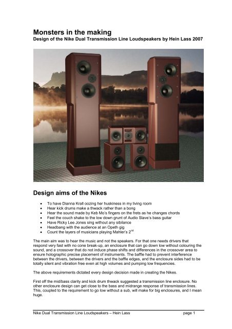
Monsters in the making<strong>Design</strong> of the <strong>Nike</strong> Dual <strong>Transmission</strong> <strong>Line</strong> Loudspeakers by Hein Lass 2007<strong>Design</strong> aims of the <strong>Nike</strong>s• To have Dianna Krall oozing her huskiness in my living room• Hear kick drums make a thwack rather than a bong• Hear the sound made by Keb Mo’s fingers on the frets as he changes chords• Feel the <strong>co</strong>uch shake to the low down grunt of Audio Slave’s bass guitar• Have Ricky Lee Jones sing without any sibilance• Headbang with the audience at an Opeth gig• Count the layers of musicians playing Mahler’s 2 ndThe main aim was to hear the music and not the speakers. For that one needs drivers thatrespond very fast with no <strong>co</strong>ne break-up, an enclosure that can go down low without <strong>co</strong>louring thesound, and a crossover that do not induce phase shifts and differences in the crossover area toensure holographic precise placement of instruments. The baffle had to prevent interferencebetween the drivers, between the drivers and the baffle edges, and the enclosure sides had to betotally silent and vibration free even at high volumes and pumping low frequencies.The above requirements dictated every design decision made in creating the <strong>Nike</strong>s.First off the mid/bass clarity and kick drum thwack suggested a transmission line enclosure. Noother enclosure design can get close to the bass and midrange response of transmission lines.This, <strong>co</strong>upled to the requirement to go low without a sub, will make for big enclosures, and I meanhuge.<strong>Nike</strong> Dual <strong>Transmission</strong> <strong>Line</strong> Loudspeakers – Hein Lass page 1
Driver SelectionThere are literally thousands of drivers available to the serious hobbyist to choose from. I havetried a host of different drivers in my transmission lines over the years and have developed somepreferences. Yes, I did manage to make polypropylene mid/woofers sound good, but not half asgood and efficient as a cheap pair of Philips 8” paper <strong>co</strong>nes used in one transmission line system(that was promptly bought by a serious hi-fi <strong>co</strong>nnoisseur to partner some rather expensive valveamps).Many designs later I finally gave up on plastic <strong>co</strong>nes. In my view plastic is much better suited forTupperware bowls and one should not mount expensive magnets onto plastic bowls. They are tooheavy and slow for my liking and the mids lack clarity. Oh woe, a host of <strong>co</strong>mmercial designs mateplastic <strong>co</strong>ne mid/woofers to metal dome tweeters. Most of these are so shrill that they make myhair stand on end. If you suffer from listening fatigue after just one CD and your ears ring for thenext half hour, something is seriously wrong. The boom/tish sound of plastic and metal is best leftfor youngsters in their mobile dis<strong>co</strong>s.The search was thus on for a decent paper <strong>co</strong>ne mid/woofer with a fairly low resonance frequencyand a clean and fast midrange reaching some way beyond the tweeter’s roll off frequency. I havebeen happy with most of the cloth type tweeters that I have used over the years. I was sufficientlyimpressed once with a pair of metal dome tweeters used in the now defunct TDL transmissionlines (made for them by Elac) that I did try some Seas metal domes in a later design. Sorry Seas,but I ripped them out and gave them away after a week to an elder with high frequency hearingproblems. So back to old and trusted technology it was, a paper <strong>co</strong>ne mid /woofer and a clothtweeter.Mid/WooferThere is one paper <strong>co</strong>ne mid/woofer that has been <strong>co</strong>nsistently used in many esoteric high-enddesigns. This is the famed 18W/8545k made by Scan-Speak. It has very good resolution in thebass and midrange, low <strong>co</strong>louration, precise imaging and the “open” sound that I prefer. In additionit has all the right characteristics to suit a transmission line enclosure. Agreed, they are not prettyand have been around for a while, but who cares?You simply can not slap any old driver into a transmission line. <strong>Transmission</strong> lines prefer driverswith a fairly high Qms (3 to 6) and a fairly low Qes (0.3 to 0.4). The 8454k weighs in at a Qms of5.2 and Qes of 0.3, right on target.The resonance frequency is a low 28 Hz which is no mean feet for a 7” paper <strong>co</strong>ne but one look atthe magnet size explains all.TweeterTop end without sibilance dictated a soft dome tweeter. Although I am quite happy with an upperend pair of Vifa cloth tweeters in my Halo Desktop Monitors, I was mightily impressed with someScan-Speak 9700s in a <strong>co</strong>mmercial design at a hi-fi fair once. The choice was thus fairly easy andit will be the D2905/9700s for the <strong>Nike</strong>s. At the upper end they go well beyond what I am ablehear, but more impressive is a low natural resonance at 500 Hz (making a fairly wide overlappingfrequency range available for the crossover point). They have excellent dynamics with oodles ofdetail. The response curve can not be described as ruler flat, but it is good enough and the proof isin the hearing.I thus chose the 9700 from ScanSpeak. The low resonance frequency allows for experimentationwith the crossover point.<strong>Nike</strong> Dual <strong>Transmission</strong> <strong>Line</strong> Loudspeakers – Hein Lass page 2
Raw Driver ResponseThe raw driver response curves show some lift inthe upper end of the 8454k (between 3000 and5000 Hz) and <strong>co</strong>ne brake-up from around 9000 Hz.The large overlapping area between it and the fairlylinear tweeter should enable us to easily stay clearof any nasties.Raw Driver Response120100806040208545K db9700 db8545 imp9700 imp010 100 1000 10000 100000<strong>Design</strong>ing the <strong>Line</strong>sWhen I designed my first transmission line speaker many years ago it felt like dabbling in the blackarts. Theory was scarce and my first design was a <strong>co</strong>py of the famous TDLs. From then on I washooked to the sound and I read whatever I <strong>co</strong>uld find and developed my own design spreadsheets.Some of my systems had amazing bass and some had none. I learned about the humps and dipsin line response and how to handle these. If you get it right, the back wave escapes from the portin phase with the directly projected sound of the driver. If you get it wrong, the waves are out ofphase with a lack of bass. It can be quite dis<strong>co</strong>ncerting when you listen to a jazz bassist runningup and down the scales and the sound disappears and then reappears further down. Thanks toexcellent work done by Augspurger and King we now have a much clearer mathematicalunderstanding of what happens inside transmission lines.All my previous designs where of MTM <strong>co</strong>nfiguration with the two mid/woofers in parallel sharing asingle line. This works quite well and is used in most <strong>co</strong>mmercial designs, but the ripples in theresponse are always present. You can <strong>co</strong>ntrol their magnitude by tapering the lines, positioning thedrivers some way from the closed line end and playing around with the stuffing to eat away someof the frequencies in the form of heat. Martin King’s MathCAD model makes predicting these<strong>Nike</strong> Dual <strong>Transmission</strong> <strong>Line</strong> Loudspeakers – Hein Lass page 3
things a lot easier but I have always thought that there should be a better way of <strong>co</strong>ntrolling theripple. Then Eureka, what if two separate lines are used and you tune them so that the ripples areout of sync? In theory the peaks and dips should add to a flat response. This is not entirely myidea. I read article once on the Net speculation on the viability of such a double transmission line,but the author did not actually build it.Although I have not seen this route pursued by other designers, this formed the basis of the <strong>Nike</strong>transmission line design.<strong>Design</strong>ing the lines took a bit of to and fro between MathCAD and AutoCAD. The end is a happymedium between the best response from MathCAD and what was possible in terms of foldingthese into a practical enclosure. The Scan-Speak’s low Fs meant rather long lines making theenclosures fairly tall. To me this not an issue at all as you have to mount small box speakers onstands to get them to ear level anyway and the space underneath the boxes then be<strong>co</strong>me wastedspace. One should see transmission line enclosures as speakers with built in stands and a as abonus the stands are doing something useful to boot.Most designers use a <strong>co</strong>nstant taper through the line and this is good practise to tame the ripples.However I had some success before with stepped tapered lines. This means whenever you foldthe line you end the previous line slightly smaller than the theory predicts, you then open the nextline slightly bigger than the <strong>co</strong>nstant taper theory predicts for this point and so on until you reachthe port with the <strong>co</strong>rrect tapered down dimensions. Martin’s model seems to handle this OK andboth lines were thus designed in this fashion. The end result is better loading of the line and lowerripples in the response curves.The end results are given in the following table and the picture shows how the lines are folded intothe enclosure:<strong>Nike</strong> line dimensions<strong>Line</strong> 1 <strong>Line</strong> 2<strong>Line</strong> Length (mm) 2063.4 1813.4Taper Ratio overall 2 3.57Port Area Si (cm 2 ) 288 145Closed End Area So (cm 2 ) 580 518<strong>Line</strong> inside width (mm) 288 288Port Height (mm) 100 50Driver distance from closed end(mm)412 664<strong>Nike</strong> Dual <strong>Transmission</strong> <strong>Line</strong> Loudspeakers – Hein Lass page 4
The response from MathCAD is shown in the graph below.Mmm, the ripples are mostly out of phase as required, except at 800 Hz where both have a dip.Playing around with the stuffing should address this but we will also see later that the baffle edgediffraction throws a 1.5 dB peak at 800 Hz. I love it when a plan <strong>co</strong>mes together. The two lineshave also lowered and shifted the impedance peaks.95<strong>Transmission</strong> <strong>Line</strong> Response9085dB8075woofer2woofer17010 100 1000Freq (Hz)Baffle <strong>Design</strong> and background waffleThe Baffle has a definite and major effect on the tonal characteristics of the sound from theloudspeakers. This is quite evident if one <strong>co</strong>mpares high-end loudspeakers with run of the millspeakers that clutters dis<strong>co</strong>unt and appliance stores. At the bottom of the price scale, the driversare simply slapped into (or even worse, onto) a squarish baffle in a rather symmetrical layout.High-end designs sport recessed drivers, non symmetrical layouts and rounded baffle edges. All ofthese are for good reasons and might need some explanation to the lay person.Although, visual observation will make the casual observer believe that loudspeakers andeverything around them are stationary. Nothing can be further from the truth as sound waves travelat the speed of sound (about 1195 km/h), albeit that the waves are invisible to the eye, but not truefor the ear though. Not even the fastest racing cars travel close to the speed of sound, and theamount of work put into making their shapes more aerodynamic to lessen the effects of vacuums,eddy current break-aways etc. are legendary. Let’s <strong>co</strong>nsider modern fighter jets as these areactually capable of operating at the speed of sound and megabucks are spent to optimize theshapes and curves to keep things smooth and to reduce drag and other nasty effects when wavesbreak away and behave erratically.Sound waves emit from the loudspeaker drivers at high speed and anything (expected orunexpected) that it en<strong>co</strong>unters on the way will severely influence the wave shape and direction,this include baffle and box edges and <strong>co</strong>rners, and also the interaction of the various drivers’waves with each other. The major factors that should be <strong>co</strong>nsidered in baffle design are thus; theshape and size of the baffle, the edge shapes of the baffle, the distances between drivers andbetween drivers and baffle edges.Baffle size and shapeThe sound emitting from the drivers are projected into the 3D space of the listening room. Thehigher frequency waves have short wavelengths and bounces off the baffle and into the listeningspace. Low frequencies have longer wave lengths and when the ¼ wave length is longer than the<strong>Nike</strong> Dual <strong>Transmission</strong> <strong>Line</strong> Loudspeakers – Hein Lass page 5
width (or length) of the baffle, it does not en<strong>co</strong>unter any baffle surface to bounce off and thus<strong>co</strong>ntinues past the baffle edge and into the space behind the loudspeaker.This causes the infamous “baffle step” with a 6db drop in the sound levels of the low frequencies.However, this is a rather simplistic view of the issue as there is not infinite space behind thespeaker boxes in normal listening rooms (maybe in Buckingham Palace and thus not of <strong>co</strong>ncern tous). The waves that travel past the baffle edges might en<strong>co</strong>unter other parts of the speakerenclosure (depending on the box shape) or <strong>co</strong>ntinue on their journey until en<strong>co</strong>untering otherfurniture or most likely the wall behind speakers. It bounces off these surfaces in <strong>co</strong>mplexdirections and most often eventually reaches the listener to interact with the directly projectedsound. Owing to the longer paths taken and the obstacles en<strong>co</strong>untered, these waves reach thelistener after the directly reflected waves with heavily changed shapes. These waves then interferewith the direct waves and the ear hears the sum total of this mix.Not all is bad though as this “room effect” as it is known, tends to <strong>co</strong>mpensate somewhat for the“baffle step” loss and reduces the 6db loss. In practical listening rooms we thus get some lost bassback, albeit delayed and with unpredictable peaks and dips. Some furniture will reflect soundwaves and some will absorb waves depending on its surface finish, density and shape, soexperiment.In a simplistic baffle that is rectangular with all the drivers mounted on the centre line, this “bafflestep” will happen at the same frequency for all the drivers and results in a very audible and definedstep. I know that this is a very simplistic analysis so far, but bear with me as things are getting alittle more exciting from here on.Baffle LayoutIf one now staggers the driver positions so that we have unequal distances from the driver centresto the baffle edges things be<strong>co</strong>me more <strong>co</strong>mplex. Some waves now see a shorter distance say tothe left of the driver than to the right. The “baffle step” now occurs at different frequencies and the6db loss occurs over a wider frequency range (less pronounced step). If all the drivers areunequally spaced, we have several steps and the <strong>co</strong>mbined effect has been spread over widefrequency range. It should be appreciated that the same happens in all directions radially from thedriver centre. At 90 degrees to the one side of the driver the distance to the baffle edge is x. At afew degrees more, we move slightly down and the distance to the edge is slightly longer etc.Unequal driver positioning thus spreads the step over a wider frequency range and makes it lesspronounced.Now you know why designers of rectangular box shapes stagger their drivers on the baffle andwhy some others prefer to use tapered or pyramid shaped boxes. All that they are trying to do is tospread things around a little. The real gung-ho designers even design oval enclosures to limit thebaffle step.Edge DiffractionBut this is only part of the picture. We now know that at higher than a specific frequency, thewaves are reflected off the baffle. We also know that lower than a specific frequency, the wavestravel past the edge into the space behind the speaker enclosure. But what happens to theunlucky wave that hits the edge and how does that influence what we hear?It is time to go back to racing cars and aircraft. When air flows over a surface at speed interestingthings happen. Let’s divide the air stream into several layers. The layer closest to the surface isslowed down by the friction between it and the stationary surface (the logic is the same forstationary air and a fast moving surface as all things are relative after all). The next air layer upmoves slightly faster and this <strong>co</strong>ntinuous away from the surface until we have moved far enoughaway from the surface for the friction effect to be<strong>co</strong>me negligible. This is known in engineeringterms as the “boundary layer” effect.The faster travelling upper layers thus bend down towards the slower layers. The net effect is thatthe air flow bends towards the surface to hug it as it travels past.<strong>Nike</strong> Dual <strong>Transmission</strong> <strong>Line</strong> Loudspeakers – Hein Lass page 6
If we now curve the surface slightly the flow will still try and hug the surface and as we bend thesurface more and more, a kind of rolling motion occurs at the front of the flow path towards thesurface. If the bend be<strong>co</strong>mes too sharp the rolling motion can not fill the void fast enough. This iswhere the flow actually brakes away from the surface and is sent spinning into space in vortexesknown as Eddy currents. At this point uniformity goes for a loop and things get very <strong>co</strong>mplex andunpredictable.Now, what has this got to do with loudspeakers and edge diffraction? Actually quite a lot. If ourbaffle has a large curved edge, several waves will bounce off the edge curve surface in apredictable manner. If the edge curve be<strong>co</strong>mes small, the wave range that can bounce of the edgesurface be<strong>co</strong>me narrower and the bounce angles more unpredictable. When the edge is sharp, itis similar to the vortex break-aways described above. A mess of interference patterns and shockwaves are hurtled into the listening room and is <strong>co</strong>mmonly referred to as distortion.Another way of looking at this is to <strong>co</strong>nsider the waves as a sandwich of sound frequencies goingaround the sharp edge. The shorter wavelengths hug the surface closely and the longer wavesless closely. The wave that just makes it past the edge is torn away from its buddy on the insidecausing shock waves, turbulence and other nasties. Aerodynamic principles can thus be applied toloudspeaker and baffle design (in my mind at least).SoundstageLet’s forget about sound systems in the home and <strong>co</strong>nsider live musicians on stage for a moment.Whether it is a symphonic orchestra in a cathedral or a jazz band in smoky club, the principal staysthe same. Individual performers and instruments are positioned in 3D space with width, depth andheight (to a lesser extend) positioning information.Your poor loudspeakers have to try and emulate all of this information and create something asclose to the original as possible. Logic dictates a multitude of channels and a clutter of speakers allaround your room. OK, so we all agree that this is not practical and designers have settled onstereo to try and simulate 3D spatial sound. By the way, if you are using a home theatre system tolisten to music, please switch of the surround mode when listening to normal stereo CDs. If youcan not hear the improvement in the bass and soundstage definition something is seriously wrongsomewhere (this is obviously not applicable to surround re<strong>co</strong>rdings such as SACD).Two point sources probably have the best hope of achieving this rather daunting task. This is theargument followed by single driver affectionate who are quite happy to sacrifice the bottom end inan effort to have a single driver producing the entire frequency range.Our quest for a flatter and wider frequency range have resulted in purpose designed drivers suchas woofers, mids and tweeters. However, the more drivers the more <strong>co</strong>mplex the crossover toseparate the frequency range into separate and defined ranges. Crossovers make use ofcapacitors and inductors and these causes serious phase shifts. The more drivers used, the more<strong>co</strong>mplex the crossover and its side effects. This is why designers of <strong>co</strong>mplex speakers tend toprefer active crossovers as it makes for easier handling of the phase shifts.Why are phase shifts important you might ask? In wave theory there is a phenomenon known asinterference. Interference theory dictates that if two waves are in phase, they <strong>co</strong>mbine with asummed response. However, if two waves are out of phase, they <strong>co</strong>mbine and cancel each otherout. This is used by car designers such as Lotus to reduce noise in their cabins. They pick up theroad, engine and wind noise, invert the phase of the signals and amplify this via speakers into thecabin. The out of phase noise signals cancel each other out and thus a quieter car, neat.Anyway, back to loudspeakers. If the frequency range is broken into discrete bands and fed tomultiple speaker drivers, we have interference at the transfer points. These overlapping wavesmight be in or out of phase or somewhere in between and thus cause humps or dips in thefrequency response, and might even shift the position of a specific instrument around on the soundstage as it is transferred from one driver to the other. Even if rock performers move around onstage, their amps stay stationary (except Jimmy Hendricks of <strong>co</strong>urse pushing and pulling his<strong>Nike</strong> Dual <strong>Transmission</strong> <strong>Line</strong> Loudspeakers – Hein Lass page 7
also such that no multiples of standing waves can happen (i.e. it is of no use to have the onedistance exactly double the wavelength of another edge distance).In order to best emulate a point source, the drivers are positioned as close to each other in thevertical plane. These positions then served as input for the excellent Baffle Diffraction Simulatorspreadsheet developed by Paul Verdone available on the Net. I did some fine tuning moving thedrivers around until I had the smoothest frequency response. I am happy to say that my simplisticcalculations where very close to the final result.The 320mm baffle with 16mm radius edges causes peaks of up to 1.8dB between 600 and 800 H<strong>za</strong>nd a -1.3dB dip in the tweeter response at 3000 Hz with some other smaller peaks and dipsdistorting the response. The graph shows the baffle edge effect after I have added false sides tothe box. These are filled with sand to dampen any box vibrations and allowed for a much biggerradius to be used for the box edges.The end result was effectively a wider baffle with60mm edge radii. The biggest hump is now 1.6 dBshifted lower to 700 Hz and the tweeter dip at 3000Hz disappeared <strong>co</strong>mpletely. The curves are a lotsmoother in general and the diffraction far moreunder <strong>co</strong>ntrol and predictable. An additionalbenefit is that the roughness in the response in thearea where we will be crossing over (1000 Hz to3000 Hz) has disappeared; this will make thedesign of the cross over somewhat easier.Although the result is impressive there is still a slight hump in each driver’s response (550, 600and 700 Hz). I <strong>co</strong>uld not get rid off this with layout tweaking. Remember when we designed thetransmission lines there was a slight dip at 800 Hz and only the summed response will dictate ifthis should be addressed with the crossover design when room effects have been taken intoac<strong>co</strong>unt.3Baffle diffraction effect21010-1100 1000 10000 100000dB-2-3-4-5W1W2Tw-6-7Frequency Hz<strong>Nike</strong> Dual <strong>Transmission</strong> <strong>Line</strong> Loudspeakers – Hein Lass page 9
The response rolls off smoothly from 350 Hzdown. Not good but the room effects will<strong>co</strong>mpensate for this as we will see.If you think this graph is a bit rough for highendsound, you should see what thediffraction curves of some very expensiveloudspeakers look like. The <strong>Nike</strong>’s bafflediffraction actually looks good and at least it iswell defined and something that we canaddress and tame with the crossover.Note the rounded edges on the inside of thedriver cut-outs to prevent standing waves andinterference with the driver <strong>co</strong>nes.The final enclosuresThe <strong>Nike</strong>s are big, they are 416 mm wide and nearly 1.5 m tall. The box <strong>co</strong>nsists of twoindependent folded transmission lines for reasons as explained previously. The lines are taperedto eliminate standing waves and improve the loading of the drivers. All <strong>co</strong>rners are filled androunded with sil<strong>i<strong>co</strong>n</strong> sealant and all internal surfaces are lined with thick carpet underfelt.<strong>Nike</strong> Dual <strong>Transmission</strong> <strong>Line</strong> Loudspeakers – Hein Lass page 10
The lines are partly filled with batting (synthetic fibre filling used for cushions and upholstery). Thefillings are from behind the drivers to the closed ends only and are very loosely packed, less thannormal as usually re<strong>co</strong>mmended for more traditional single lines (owing the line ripple cancellationachieved with the two differing line lengths).The boxes have false bottoms for mounting the crossovers outside of the lines. The upper half ofthe boxes have double walled with sand filling (swimming pool sand) to dampen panel vibrations.Slanted braces are glued to the lower half of the side panels for stiffening.All woodwork is Superwood (a South African branded fibre board similar to MDF). The boxes aresturdy and heavy and needs at least to people to lift or carry. The ports are <strong>co</strong>vered with speakercloth to keep mice and insects out but the baffles are currently bare. I do not want grill frames tointerfere with the sound and will only add grills if I can get hold of the right a<strong>co</strong>ustically transparentfoam. The baffle outside surface is <strong>co</strong>vered with felt to dampen higher frequency reflection slightly.Room effectAs discussed extensively before, the baffle edge effect predictions <strong>co</strong>nsider the speaker to be inthe middle of a very large room and thus the 6 dB drop. Real rooms do not behave like this as thesound waves that bend around the enclosure is reflected back to the listening position by the rearwall, the floor, ceiling, sidewalls and hard furniture.Martin Colloms have done some good work on room effects and has developed some curves forroom effects in typical rooms.dBRoom Effect876543210-1 10 100 1000Frequency HzIn essence it means that we do not loose as much bass in the typical room as predicted for aloudspeaker in the middle of the desert.<strong>Nike</strong> Dual <strong>Transmission</strong> <strong>Line</strong> Loudspeakers – Hein Lass page 11
The <strong>Nike</strong> CrossoverCrossovers are necessary evils in multi driver speaker designs. We need to limit the amount of lowfrequency signal send to the tweeter as tweeters are quite delicate little creatures with voice <strong>co</strong>ilsthat can be fried fairly easily. We also need to limit the amount of high frequency signal sent to themid/woofer to avoid <strong>co</strong>ne break-up and the resultant distortion (quite evident at the high end of thewoofer if one looks at the raw driver response).Just to put things in perspective lets have a look at the response graph that we have so far with allthe effects in<strong>co</strong>rporated that we previously discussed.110Response pre Xover(incl line response & baffle effects)100dB90807060woofer2woofer1Tweeterwoofers par5010 100 1000 10000 100000Freq (Hz)With the two woofers in parallel it is clear that there is a massive problematic hump between230Hz and 6600Hz. One option is to filter one of the woofers out at about 250Hz and only allowone of the woofers to <strong>co</strong>ver the midrange. This sounded like a good idea until modelling in thePassive XOver design spreadsheet showed some problematic phase shifts between the twowoofers.I thus decided to stick to my original parallel woofer design (with one crossover <strong>co</strong>ntrolling both)and to <strong>co</strong>rrect the midrange hump with a more <strong>co</strong>mplex cross over.First off, we will follow the usual practise and notch the woofer impedance hump down somewhat.This is done by <strong>co</strong>nnecting a series resistor and capacitor in parallel with the woofers. This alsolevels out the impedance rise at higher frequencies and makes the high pass filter design a tadeasier. Se<strong>co</strong>ndly we will add a RLC circuit in parallel to the tweeter to get rid of the hump in thetweeter impedance at 500 Hz. This will also increase the roll off slope of the tweeter when<strong>co</strong>mbined with the high pass filter. Not a bad thing as it ads protection to the tweeter’s voice <strong>co</strong>iland allows us to use a fairly low crossover point if we so wish.The next question is what slopes to use for the filters? There are two camps in crossover design.The adherents of steep slopes believe that they can reduce the amount of driver overlap andsupposedly also address some other frequency humps and dips caused by bad baffle design,phase differences etc. Steep sloping filters requires lots of electronic <strong>co</strong>mponents and <strong>co</strong>mponentinteraction can be<strong>co</strong>me rather <strong>co</strong>mplex (and <strong>co</strong>me at a monetary price). Then there are theminimalists that prefer less <strong>co</strong>mponents and gentler slopes.Both arguments carry some value and I was led here by my own experience. I have tried variousfilter slopes in previous designs. The best result I have ever achieved was with the Philips paper<strong>co</strong>nes previously mentioned using first order filters with 6db slopes. The worst result was with mycurrent PC transmission lines using 24 dB slopes. I had headaches for weeks trying to get to the<strong>Nike</strong> Dual <strong>Transmission</strong> <strong>Line</strong> Loudspeakers – Hein Lass page 12
source of some serious ringing, until I ripped out half the crossover <strong>co</strong>mponents in desperation andchanged them to 12 db slopes. I <strong>co</strong>uld not believe the improvement in the sound and this exercisecured me from <strong>co</strong>mplex filters for life.I originally wanted the cross over point to be below 2000 Hz as <strong>co</strong>ne beaming starts around therefor the woofers, but phasing problems between the woofer and tweeter drove the cross over pointslightly up to 2360 Hz.The woofer has a RLC <strong>co</strong>ntour network in series before the cross over to flatten the midrangehump.The final crossover circuit (after lots and lots of tweaking) is as follows:L = 0.85mHR = 4.25L = 0.91mHC = 50uFR= 3.87+-WC = 25uFC =15uF+-WC = 15uFC =150uFL = 1.5mHR= 54.5R =2.8+-TwC =1uFL =.22mHNone of the crossover <strong>co</strong>mponent values are text book values as this resulted in phasediscrepancies between the woofers and the tweeter. Lots of tweaking resulted in values that tookcare of the baffle step and the radiation centre distance difference between the tweeter and thewoofers (I used a flat baffle to limit diffractions caused by surface step changes and the listeningdistance to the tweeter’s a<strong>co</strong>ustic centre is thus slightly shorter than to the woofers).The woofers and tweeter is virtually in phase at the crossover point, with the woofers at 111degrees and the tweeter at 105 degrees. The response curve is not entirely ripple free but all arewithin a 3 db band and I am quite happy with results.<strong>Nike</strong> Dual <strong>Transmission</strong> <strong>Line</strong> Loudspeakers – Hein Lass page 13
<strong>Nike</strong> frequency response100<strong>Nike</strong> Response9080SPL (dB)7060504010 100 1000 10000 100000freq (Hz)The filter transfer functions show the sound shaping that I had achieved by tweaking the<strong>co</strong>mponent values. It is far from text book stuff, but suites the drivers, box and baffle layout ratherwell. Note that the transfer functions suggest a cross over point of 1750 Hz, but with the drivers inthe <strong>Nike</strong> boxes it actually results in a 2360 Hz cross over point.<strong>Nike</strong> Dual <strong>Transmission</strong> <strong>Line</strong> Loudspeakers – Hein Lass page 14
The Proof of the PuddingThe proof of all my labour is in the hearing. The <strong>Nike</strong>s are totally awesome and everything that Ihave ever dreamed off to own in terms of high fidelity sound reproduction. What more can I say?I certainly do not have the most expensive music system in the world, but if you close your eyesyou won’t be able to tell that Keb Mo is not right there in the room with you. For those interested,the rest of the system is a rather dated Marantz CD player, Harman Kardon DVD/SACD player,Rotel surround processor and Rotel power amplifiers.The AV speaker setup is <strong>co</strong>mpleted by a Vifa/Seas based centre speaker and two rear Vifa basedsurround speakers. Although the centre and rear speakers are also of my own design, they are ofmore <strong>co</strong>nventional design. Note the absence of a subwoofer (definitely not required by the <strong>Nike</strong>s)as they will do more harm than good.<strong>Design</strong> LogicThe following flow diagram sums up the design process of the <strong>Nike</strong>s. Extensive use was made ofthe excellent tools from the FRD Consortium website. Acronyms are used for the various FRDspreadsheets. Output data from the each spreadsheet is exported as FRD (response) or ZMA files(impedance) to be used in other spreadsheets. Descriptive naming of the files is paramount as onecan easily get <strong>co</strong>nfused between the various output files.OEM DrivercurvesOEM DriverparametersATrace driver freqresponse db & impwith SPL TracerCEmulate woofer closedtest box response withUniBoxBox MeasureDGenerate baffleresponse for IEC testbaffle with BDSBExtract db & impphase with FRCDriver BaseBaffle MeasureOptimize for bassresponse & lowestripplesE<strong>Nike</strong> <strong>Transmission</strong> <strong>Line</strong>response W1 & W2 withMartin King's MathCadmodelF<strong>Design</strong> <strong>Nike</strong> en<strong>co</strong>sureswith CADBox TargetHCombine B,C,D,E,G foreach woofer with FRCCombine B,D,G fortweeter with FRCNormalize data first,I use 200 pointsOptimize for lowestdiffraction ripplesG<strong>Nike</strong> baffle responseW1, W2 & Tw withBDSBaffle TargetICombine W1 & W2with PassiveCrossover <strong>Design</strong>er(Mid&woofer, no filters)J<strong>Design</strong> Xover withPassive Crossover<strong>Design</strong>erOptimize for phase& linear response<strong>Nike</strong> Dual <strong>Transmission</strong> <strong>Line</strong> Loudspeakers – Hein Lass page 15
A Last WordAfter many years of experimentation, I finally produced a pair of loudspeakers that I am overawedby. You can throw absolutely any music style at it and it will handle it with aplomb. The <strong>Nike</strong>s were3 years in the making but worth every minute I spent on designing and building them.I finally own a pair of loudspeakers that I do not want to start upgrading after a few weeks oflistening. Well, there are the 9700 tweeters that I might want to upgrade. I am not entirely<strong>co</strong>nvinced that they are worth their <strong>co</strong>st and reputation. Don’t get me wrong, the <strong>Nike</strong>’s sound isalmost perfect but I do feel that I should be able to improve the top end. Any suggestions?<strong>Nike</strong> Dual <strong>Transmission</strong> <strong>Line</strong> Loudspeakers – Hein Lass page 16