Webra fuel pressure regulator Order No. 3712 - RC Universe
Webra fuel pressure regulator Order No. 3712 - RC Universe
Webra fuel pressure regulator Order No. 3712 - RC Universe
- No tags were found...

You also want an ePaper? Increase the reach of your titles
YUMPU automatically turns print PDFs into web optimized ePapers that Google loves.
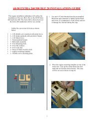
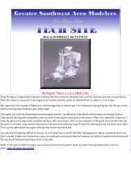
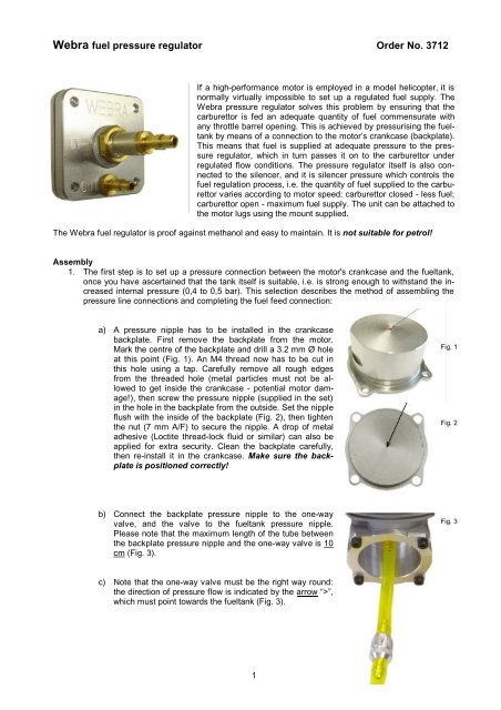
<strong>Webra</strong> <strong>fuel</strong> <strong>pressure</strong> <strong>regulator</strong> <strong>Order</strong> <strong>No</strong>. <strong>3712</strong>If a high-performance motor is employed in a model helicopter, it isnormally virtually impossible to set up a regulated <strong>fuel</strong> supply. The<strong>Webra</strong> <strong>pressure</strong> <strong>regulator</strong> solves this problem by ensuring that thecarburettor is fed an adequate quantity of <strong>fuel</strong> commensurate withany throttle barrel opening. This is achieved by pressurising the <strong>fuel</strong>tankby means of a connection to the motor’s crankcase (backplate).This means that <strong>fuel</strong> is supplied at adequate <strong>pressure</strong> to the <strong>pressure</strong><strong>regulator</strong>, which in turn passes it on to the carburettor underregulated flow conditions. The <strong>pressure</strong> <strong>regulator</strong> itself is also connectedto the silencer, and it is silencer <strong>pressure</strong> which controls the<strong>fuel</strong> regulation process, i.e. the quantity of <strong>fuel</strong> supplied to the carburettorvaries according to motor speed: carburettor closed - less <strong>fuel</strong>;carburettor open - maximum <strong>fuel</strong> supply. The unit can be attached tothe motor lugs using the mount supplied.The <strong>Webra</strong> <strong>fuel</strong> <strong>regulator</strong> is proof against methanol and easy to maintain. It is not suitable for petrol!Assembly1. The first step is to set up a <strong>pressure</strong> connection between the motor's crankcase and the <strong>fuel</strong>tank,once you have ascertained that the tank itself is suitable, i.e. is strong enough to withstand the increasedinternal <strong>pressure</strong> (0,4 to 0,5 bar). This selection describes the method of assembling the<strong>pressure</strong> line connections and completing the <strong>fuel</strong> feed connection:a) A <strong>pressure</strong> nipple has to be installed in the crankcasebackplate. First remove the backplate from the motor.Mark the centre of the backplate and drill a 3.2 mm Ø holeat this point (Fig. 1). An M4 thread now has to be cut inthis hole using a tap. Carefully remove all rough edgesfrom the threaded hole (metal particles must not be allowedto get inside the crankcase - potential motor damage!),then screw the <strong>pressure</strong> nipple (supplied in the set)in the hole in the backplate from the outside. Set the nippleflush with the inside of the backplate (Fig. 2), then tightenthe nut (7 mm A/F) to secure the nipple. A drop of metaladhesive (Loctite thread-lock fluid or similar) can also beapplied for extra security. Clean the backplate carefully,then re-install it in the crankcase. Make sure the backplateis positioned correctly!Fig. 1Fig. 2b) Connect the backplate <strong>pressure</strong> nipple to the one-wayvalve, and the valve to the <strong>fuel</strong>tank <strong>pressure</strong> nipple.Please note that the maximum length of the tube betweenthe backplate <strong>pressure</strong> nipple and the one-way valve is 10cm (Fig. 3).Fig. 3c) <strong>No</strong>te that the one-way valve must be the right way round:the direction of <strong>pressure</strong> flow is indicated by the arrow “>”,which must point towards the <strong>fuel</strong>tank (Fig. 3).1
2. The recommended method of mounting the<strong>pressure</strong> <strong>regulator</strong> is to use the mountingplate supplied (Fig. 4), which can be securedon top of one motor lug using the standard retainingscrews. The example illustrates onepossible option for which there is space inmost model helicopters. This method ofmounting ensures that the <strong>pressure</strong> <strong>regulator</strong>is located in the immediate vicinity of the carburettor.The shorter the link to the carburettor,the more reliable the system! The <strong>pressure</strong><strong>regulator</strong> itself is attached to the mountingplate by fitting the <strong>pressure</strong> <strong>regulator</strong> nozzlethrough the slot, and tightening the retainingnut over the shakeproof washer. Place the<strong>pressure</strong> <strong>regulator</strong> housing in the desired positionbefore tightening the nut fully. The outletnipple on the <strong>pressure</strong> <strong>regulator</strong> (marked“OUT”) can now be connected to the carburettorfeed nipple by means of a length of <strong>fuel</strong>tubing.Fig. 4Mounting plate3. Connect the <strong>fuel</strong>tank to the inlet nipple on the<strong>pressure</strong> <strong>regulator</strong> (marked “IN”) (Fig. 4). Wealways recommend that you use a <strong>fuel</strong> filter; ifyou prefer to install one outside the <strong>pressure</strong><strong>fuel</strong>tank, then it should be fitted in this <strong>fuel</strong>line.4. The next step is to connect the <strong>pressure</strong> <strong>regulator</strong>to the silencer using another length of<strong>fuel</strong> tubing. The nipple for this is located onthe rear face of the <strong>pressure</strong> <strong>regulator</strong>; connectthis to the <strong>pressure</strong> outlet nipple on thesilencer or tuned pipe (Fig. 5). The <strong>pressure</strong>line should be as short as possible; do notmake it any longer than physically necessaryto complete the connection.Fig. 5For the <strong>pressure</strong> and <strong>fuel</strong> feed lines it is important to use silicone <strong>fuel</strong> tubing with an internal diameter of2 mm or larger. Once you have completed all the connections, please check each one and ensure that it issecured properly. It is a good idea to secure the <strong>pressure</strong> lines on the nipples using hose clips.Do check that the <strong>fuel</strong>tank does not leak, i.e. is completely sealed. The system can only work effectively ifthe tank and the filler valve are effectively sealed.Starting the motorPressure needs to be built up before you start the motor. This is done by sealing the outlet of the silencer ortuned pipe with a finger for a few moments while you fire up the motor. Release the outlet pipe immediatelythe motor starts. When the motor is running, you will find that the carburettor needs to be adjusted; this isinevitable due to the change in <strong>fuel</strong> supply conditions.2
Fault-findingIt is important to check the <strong>pressure</strong> system from time to time. Leaks in the <strong>pressure</strong> lines may cause a lossof <strong>pressure</strong>, which will interfere with the operation of the <strong>regulator</strong>y system; escaped <strong>fuel</strong> may indicate a<strong>pressure</strong> leak.If you notice a change in the operation of the <strong>regulator</strong>, the cause could also be particles of dirt in the <strong>regulator</strong>ysystem, carried by the <strong>fuel</strong>:a) Check for soiling in the <strong>pressure</strong> line from the silencer (or tuned pipe) to the <strong>pressure</strong> <strong>regulator</strong>;b) Check for soiling (oil residue, dirt particles) in the <strong>pressure</strong> line from the backplate <strong>pressure</strong> nipple to the<strong>fuel</strong>tank, and also in the one-way valve.c) Check for dirt particles inside the <strong>pressure</strong> <strong>regulator</strong>, or the inlet valve of the <strong>pressure</strong> <strong>regulator</strong>.Cleaning the system: first remove the <strong>pressure</strong> <strong>regulator</strong> from its mounting, then carefully undo the fourhousing screws and separate the top and bottom sections. Check for dirt particles between the membraneand the housing section and remove them - but please be careful: when re-assembling the parts ensurethat the small peg on the valve piston faces the inlet valve, and that the small bulge of the <strong>pressure</strong> membranerests against the valve piston. Check for soiling also in the inlet valve of the <strong>pressure</strong> <strong>regulator</strong>: unscrewthe <strong>pressure</strong> nipple marked “OUT”; you will find a compression spring and a valve ball behind it.Please be careful handling these parts, as they must be re-assembled exactly in their original position.The one-way valve is screwed together tightly, but can be opened by unscrewing the knurled section of thehousing. Once again, please be careful, as there is a small compression spring and a valve plate inside thehousing. Clean the parts, then re-assemble them and re-install the valve the right way round (arrow mark).All <strong>pressure</strong> lines can be washed out using normal glow <strong>fuel</strong>.We hope that you are satisfied with our product, and enjoy using it.WEBRA Modellmotoren GmbH & Co. KGA-2551 Enzesfeld / AustriaOverall view of the system connections3
DRUCKREGLERPRESSURE REGULATOR<strong>Order</strong> <strong>No</strong>. <strong>3712</strong>Artikel Nr. <strong>3712</strong>/06 /05 /01/06 /02/05/04<strong>3712</strong>/23./201 ./201./202/201102Replacement parts<strong>Order</strong> <strong>No</strong>.Pressure <strong>regulator</strong> housing <strong>3712</strong> /01Pressure <strong>regulator</strong> membrane <strong>3712</strong> /02Nipple set <strong>3712</strong> /04Screw / nut set <strong>3712</strong> /05Regulator valve set <strong>3712</strong> /06One-way valve <strong>3712</strong> /20One-way valve housing <strong>3712</strong> /201One-way valve set <strong>3712</strong> /202Mounting plate <strong>3712</strong> /23Pressure nipple + nut 11024