Prestressed Concrete Beams, (PDF) - Transport
Prestressed Concrete Beams, (PDF) - Transport
Prestressed Concrete Beams, (PDF) - Transport

Create successful ePaper yourself
Turn your PDF publications into a flip-book with our unique Google optimized e-Paper software.
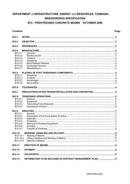
DEPARTMENT of INFRASTRUCTURE, ENERGY and RESOURCES, TASMANIABRIDGEWORKS SPECIFICATIONB12 - PRESTRESSED CONCRETE BEAMS OCTOBER 2006ContentsPageB12.1 SCOPE .............................................................................................................................................2B12.2 OBJECTIVE .....................................................................................................................................2B12.3 REFERENCES .................................................................................................................................2B12.4 MANUFACTURE..............................................................................................................................2B12.4.1 General .....................................................................................................................................2B12.4.2 Reinforcement ..........................................................................................................................3B12.4.3 Tendons....................................................................................................................................3B12.4.4 Sheathing..................................................................................................................................3B12.4.5 Bond Release Material .............................................................................................................3B12.4.6 Anchorage Devices...................................................................................................................4B12.4.7 Miscellaneous ...........................................................................................................................4B12.5 PLACING OF POST-TENSIONING COMPONENTS......................................................................4B12.5.1 Sheathing..................................................................................................................................4B12.5.2 Tendons....................................................................................................................................4B12.5.3 Anchorages...............................................................................................................................4B12.5.4 Grout Holes...............................................................................................................................4B12.6 TOLERANCES .................................................................................................................................4B12.7 PRECAUTIONS AFTER TENDON INSTALLATION AND CONCRETING ....................................5B12.8 TENSIONING OPERATIONS ..........................................................................................................5B12.8.1 General .....................................................................................................................................5B12.8.2 Equipment.................................................................................................................................5B12.8.3 Tensioning Force Required ......................................................................................................5B12.8.4 Stressing Procedure .................................................................................................................6B12.9 GROUTING ......................................................................................................................................7B12.9.1 General .....................................................................................................................................7B12.9.2 Preparation of the Ducts before Grouting.................................................................................7B12.9.3 Materials ...................................................................................................................................7B12.9.4 Properties .................................................................................................................................7B12.9.5 Mixing and Pumping Equipment...............................................................................................7B12.9.6 Grouting ....................................................................................................................................7B12.9.7 Transfer of Prestress ................................................................................................................8B12.10 MARKING, HANDLING AND DELIVERY ...................................................................................8B12.10.1 Marking of <strong>Beams</strong>.....................................................................................................................8B12.10.2 Lifting, Handling and Stacking of <strong>Beams</strong>..................................................................................8B12.10.3 Delivery of <strong>Beams</strong>.....................................................................................................................9B12.11 ERECTION OF BEAMS ...............................................................................................................9B12.12 PAYMENT ....................................................................................................................................9B12.13 HOLDPOINTS ..............................................................................................................................9B12.14 INFORMATION TO BE INCLUDED IN CONTRACT MANAGEMENT PLAN ............................9DIER SPEC B12
B12 - PRESTRESSED CONCRETE BEAMS October 2006B12.1 SCOPEThis specification covers the supply of all materials, the manufacture, handling, storage at worksand/or on site, delivery to site and erection of precast prestressed or post-tensioned beams onto theirbearings.B12.2 OBJECTIVETo ensure that prestressed and post-tensioned precast concrete beams are manufactured andinstalled to provide a durable concrete structure with the required load carrying capacity.B12.3 REFERENCESThe following Australian and British Standards apply:A.S. 1012A.S. 1310A.S. 1311A.S. 1313A.S. 1349A.S. 1379A.S. 1391A.S. 1554A.S. 1554A.S. 1720A.S. 2082A.S. 2271A.S. 2701A.S. 3600A.S. 3610A.S. 4671B.S. EN 10088-1B.S. 6744SpecificationsB10B11B14B25Methods of testing concreteSteel wire for tendons in prestressed concreteSteel tendons for prestressed concrete - Wire stress relieved steel strand for tendonsin prestressed concreteSteel tendons for prestressed concrete. Cold worked high tensile alloy steel strandbars for prestressed concreteBourdon tube pressure & vacuum gaugesSpecification and supply of concreteMethods for tensile testing of metalsStructural steel welding Part 3 Reinforcing steelStructural steel welding Part 6 Stainless steel for structural purposesTimber structures codeVisually Stress graded Hardwood for Structural PurposesPlywood and Block Board for External UseMethods of Sampling & Testing Mortar for Masonry Construction<strong>Concrete</strong> StructuresFormwork for <strong>Concrete</strong>Steel Reinforcing MaterialsStainless steels. Part 1 List of stainless steelsAustenitic stainless steel bars for the reinforcement and use in concreteSupply of <strong>Concrete</strong>.Reinforced, <strong>Prestressed</strong> and Mass <strong>Concrete</strong>Precast <strong>Concrete</strong> UnitsBridge Fence and Miscellaneous SteelworkB12.4 MANUFACTUREB12.4.1General<strong>Concrete</strong> shall comply with Specification B10. Manufacture shall comply with the requirements ofSpecifications B11 and B14.Page 2 of 10DIER SPEC B12
B12.4.2B12 - PRESTRESSED CONCRETE BEAMS October 2006ReinforcementReinforcement supply and placement shall be in accordance with Specification B11.Full strength butt welds for ligatures in the end blocks of girders shall be formed using the flash buttwelding method described in AS 1554 Part 3.B12.4.3(i)MaterialTendons• Tendons used for longitudinal stressing shall consist of uncoated, stress relieved, lowrelaxation 7-wire strand complying with AS 1311. Copies of the Manufacturer's test certificatesfor the tendons shall be submitted to the Superintendent. All coils of tendons shall be capableof being identified with the test certificates.• The material selected for use in the tendons shall have an ultimate tensile strength not lessthan the value specified on the Drawings and shall not be galvanised.• The tendons shall be supplied in coils of a sufficiently large diameter so that they are straight asthey unwind from the coils. Kinked or damaged tendons will not be permitted.(ii)(iii)TestingPhysical testing of tendons will not be required provided that a satisfactory correlation isobtained between the jacking force and extension during the stressing operation. However, ifsuch correlation is not obtained, or if the tendon exhibits any peculiarities as referred to in AS1311 usage of such tendons shall cease until physical tests have been made at a NATAregistered laboratory. Two samples each 1.4 metres long from the coil in question shall betaken and tested for ultimate tensile strength, 0.1% proof stress, 0.2% proof stress, secantmodulus of elasticity or stressing load and percentage elongation at rupture on a 600 mmgauge length. These samples shall not be taken from within 1.5 metre of the end of the coil.Fabrication• No tendon containing splices shall be used.• No welding shall be permitted on or near tendons, nor shall any heat be applied to tendons.Any tendons which have been affected by welding, weld spatter and/or heat, or otherwisedamaged shall be rejected and shall be replaced by the Contractor at its expense.• A durable metal label, on which shall be stamped the length of the tendon and the coil numberof the wire or strand used, shall be tied to each tendon.(iv)Storage and Cleaning• Coils of tendons shall be protected from the weather, chlorides, urea and other aggressivesubstances, and shall not be placed in direct contact with the ground.• All lubricant used in the drawing of the tendon shall be thoroughly removed by a suitabledegreasing agent. No rust shall be permitted on the tendons.B12.4.4SheathingSheathing shall be of a type suitable for the prestressing system to be used and shall be strongenough to withstand the placing and compaction of the concrete without suffering damage ordeformation.• The sheathing and all splices shall be mortar tight.• Sheathing shall be stored off the ground and protected from the weather at all times.• The Manufacturer's test values for the friction coefficients of the proposed sheathing shall beconfirmed by the Contractor.B12.4.5Bond Release MaterialWhere indicated on the Drawings, bond release tape, or other approved material, shall be wrappedaround tendons and shall be continued through the end forms for at least 25mm.Page 3 of 10DIER SPEC B12
B12.4.6B12 - PRESTRESSED CONCRETE BEAMS October 2006Anchorage DevicesAnchorage devices shall comply with AS 1314 Prestressing Anchorages.They shall be capable of withstanding a force not less than 95 percent of the ultimate tensile strengthof the tendon without damage or excessive draw-in or deformation. Spiral and other reinforcementspecified by the manufacturer as being required as part of the anchorage devices shall beincorporated in the works in accordance with the sizes and dimensions recommended by themanufacturer for the prestressing system to be used.Damaged or used anchorage components shall not be permitted.Components shall be handled and stored so that mechanical damage and detrimental corrosion areprevented. They shall be kept free from chlorides, urea, dirt, mortar, loose rust, tar, paint, oil or anyother deleterious matter.B12.4.7MiscellaneousLifting eyes shall be in accordance with Specification B25.B12.5 PLACING OF POST-TENSIONING COMPONENTSB12.5.1SheathingSheathing shall be securely fixed throughout its length, by methods that will hold it in position andresist movement due to flotation, concrete placement or vibration and do not damage or deform it.Joints between the sheathing and any other part of the prestressing system shall be effectivelysealed to prevent entry of mortar, dust, water or other deleterious matter.B12.5.2TendonsTendons shall be handled with care, and be pulled through the sheathing in such a manner as toavoid damage or contamination to either the tendon or sheathing.Any damaged or contaminated tendons shall be replaced at the Contractor's expense.B12.5.3AnchoragesEach anchorage device shall be set square to the line of action of the prestressing tendon and shallbe positioned securely to prevent movement during concreting.The anchorage devices shall be cleaned prior to the placing of concrete.B12.5.4Grout HolesGrout holes shall be provided at both ends of the ducts and shall be at least 10 mm diameter. Theends of the grouting holes shall be equipped with a plug, valve or similar device capable ofwithstanding a grout pressure of 700 kPa without loss of water or air. Additional vents with plugvalves shall be provided at high and / or low points of the duct to bleed air or water and to ensure theduct is completely filled after grouting.B12.6 TOLERANCES<strong>Beams</strong> shall conform to the following dimensional tolerances:a) Variations in cross section(1) Dimensions up to 200 mm -0 to +4 mm(2) 200 mm and above -0 to +7 mmb) Variation in length -7 to +7 mmor -0.06% to +0.06% of length of beam whichever is the greaterc) Twist - 0.5 deg. per length of beamd) Straightness of edges and flatness of surfaces Length / 1000Page 4 of 10DIER SPEC B12
B12 - PRESTRESSED CONCRETE BEAMS October 2006e) Maximum Vertical hogs (at stress transfer) Length / 300f) Maximum variation in hog between beams 20 mmg) Maximum deviation in the horizontal plane (bow) -7 to +7 mmh) Warpor 0.06% to +0.06% of length of beam whichever is the greater1) Up to 5 m diagonal 7 mm2) Over 5 m diagonal 10 mmi) Accuracy of corners1) up to 2m 4 mm2) over 2 m and up to 4 m 5 mm3) over 4 m 7 mmj) Spacing and position of tendons -1.5 to +1.5 mmk) Bearing seatingMaximum deviation from design plane1mmB12.7 PRECAUTIONS AFTER TENDON INSTALLATION AND CONCRETINGThe Contractor shall ensure that ducts are clear of obstructions and allow free movement of thetendons.The Contractor shall prevent damage to the ducts caused by any water freezing in the ducts prior togrouting.B12.8 TENSIONING OPERATIONSB12.8.1GeneralStressing shall not be carried out without 24 hours prior notice being given to the Superintendent.The stressing operation shall be performed under the supervision of a competent person provided bythe Contractor.No tendons shall be stressed if they are at a temperature of 0 o C or below. In addition, the airtemperature must be 5 o C or above.B12.8.2EquipmentAll tensioning equipment shall be calibrated as a complete unit by a NATA registered laboratory atleast annually in order to give a correlation between the force applied to the tendon and the readingindicated by the pressure gauge.Pressure gauges shall comply with the requirements of A.S. 1349 for industrial gauges. NATAendorsed test certificates showing such compliance shall be kept in the site office of the Contractor.B12.8.3Tensioning Force RequiredAt least 1 week prior to stressing the Contractor shall provide detailed calculations of extensionscorresponding to the required tension force at the anchorage, as shown on the Drawings, to theSuperintendent.These calculations shall be based on the secant modulus determined from the test certificates or testsamples and the expected jack and anchorage friction.The tensioning force applied to any tendon shall be determined by direct measurement of the jackgauge reading and shall be checked by measurement of the elongation of the tendon.Page 5 of 10DIER SPEC B12
B12 - PRESTRESSED CONCRETE BEAMS October 2006Under no circumstances shall the maximum jacking force exceed the rated capacity of the jackingequipment used or 85% of the specified minimum ultimate tensile strength of the tendon, whicheveris the lesser.True extension of the tendon shall be considered to be the sum of the measured extension and thezero corrected value of the extension obtained by application of the initial tension minus the amountof pull-in at anchorages and anchorage movements (if any).Whenever the actual extension and the calculated extension differ by more than 5% theSuperintendent shall be advised.B12.8.4(i)(ii)(iii)GeneralStressing Procedure• The stressing operation shall be performed in accordance with best practice applicable to theparticular system approved.• The sequence of stressing shall be as shown on the Drawings.• No structural member shall be left partly stressed unless the Drawings require the member tobe stressed in stages.• After taking up the slack, the tendon shall be accurately marked at both ends and elongationsor draw-in measured from these markings.• Where tendons consist of a number of individual components each component shall bemarked so that any slip may be observed.• Where one or more components or tendons of a group stressed together slips duringstressing operations, a compensating increase in the elongation of the remaining tendons ofthe group will be permitted provided that the jacking force does not exceed 85 percent of theminimum ultimate tensile strength of the remaining tendons.• In the case of a tendon breaking or slipping after tensioning, so that the allowable tolerancespecified above is exceeded, the tendon shall be released, replaced and re-stressed.Tensioning with one jack• Unless otherwise stated on the Drawings, the tendons may be tensioned by means of onejack only. Tendons shall be marked for measurement of elongation at both the jacking endand the anchored end, and allowance shall be made for any draw-in of the tendon at theanchored end.Stressing RecordsThe Contractor shall keep records of the stressing operation as follows:(a)(b)(c)(d)(e)(f)(g)(h)Identification number of dynamometers, gauge, pump and jack.Identification particulars of tendons.Initial forces (or pressures) when tendons are marked for measurement of elongation.Final forces (or pressures) and elongation obtained on completion of tensioning.Elongation remaining after anchoring.Elongation obtained at intervals during tensioning, together with corresponding forces(or pressures).Measured beam hog at transfer of prestress.Beam identification and date of casting and stressingCopies of the stressing records of all tendons for a particular beam shall be forwarded to theSuperintendent within 24 hours after transfer of prestress.Page 6 of 10DIER SPEC B12
B12.9 GROUTINGB12.9.1GeneralB12 - PRESTRESSED CONCRETE BEAMS October 2006Tendons shall be grouted as soon as practicable, but not more than 48 hours after fully stressing thetendons.B12.9.2Preparation of the Ducts before GroutingPrestressing anchorages shall be sealed to prevent loss of grout.The duct shall be water tested for blockages and shall be capable of sustaining a pressure of at least700 kPa without leakage. Any leaks shall be plugged.All surplus water shall be removed from the ducts prior to grouting.B12.9.3MaterialsGrout for filling prestressing sheathing shall consist of normal Portland cement, water and an additiveto reduce shrinkage and bleeding.The maximum water-cement ratio shall be 0.40 by mass.B12.9.4PropertiesThe minimum compressive strength of 75 mm test cubes made of grout shall be 30 MPa at 28 days -2 cubes to be taken from each day's grout material. Test cubes shall be made and cured inaccordance with AS 2701.4.The bleeding of the grout shall not exceed 2% of the volume 3 hours after mixing and shall notexceed 4% of the volume at any time.All separated water shall be absorbed within 24 hours. Bleeding shall be measured in a metal orglass cylinder with an internal diameter of approximately 100 mm and with a height of grout ofapproximately 100 mm. During the test the container shall be covered to prevent evaporation. Atleast one bleeding test shall be carried out for each day's grouting.B12.9.5Mixing and Pumping EquipmentGrout shall be mixed until a uniform colloidal consistency is produced. Mixing by hand, or by atumbling action, will not be permitted.Grout shall be mixed and pumped into place not more than 1 hour after the addition of cement to themix.Pumps shall be capable of continuous operation with little pressure variation, and shall have asystem for recirculating the grout whilst actual grouting is not in progress. Pumps shall be fitted witha pressure gauge and shall be capable of delivery at pressures up to 1000 kPa. The use ofcompressed air will not be permitted.All equipment, especially piping, shall be maintained in a clean condition.B12.9.6GroutingGrouting shall not be carried out while the air temperature is below 5 deg. C, or while the shadetemperature exceeds 32 deg. C. A continuous, steady flow of grout shall be maintained until the ductis completely filled and pure grout issues from all vents and all entrapped air has been expelled.The vents shall be progressively closed as required to ensure the complete filling of the duct. Thegrout pressure shall then be held at 700 kPa for ten minutes. During this period bleed water shall bebled from the crest vents at five minutes and just prior to the end of the period. After this ten minuteperiod the inlet vent shall be closed in such a way as to hold the pressure in the duct at 700 kPa. Ifany leaks occur such that the pressure over the length of the duct cannot be maintained at 700 kPa,the grouting shall be stopped, the duct flushed clean with water and the leakage plugged beforecontinuing with grouting.The quantity of materials shall be such as to enable the completion of grouting of whole duct(s)(allowing 10% wastage) without interruption.Page 7 of 10DIER SPEC B12
B12 - PRESTRESSED CONCRETE BEAMS October 2006All vents and ends shall be kept closed until final setting of the grout has taken place.All duct openings shall be inspected two or three days after grouting and topped up if necessary.In the event of difficulties occurring due to a blockage which prevents a duct from being completelyfilled with grout the grouting shall be stopped, the duct flushed clean with water and the blockageremoved before continuing with grouting.B12.9.7(i)Transfer of PrestressPost Tensioned <strong>Beams</strong>After the grout has hardened sufficiently any vents or grouting tubes which extend to the surface ofthe concrete shall be cut off 25 mm below the concrete surface and the recess plugged with anapproved concrete repair mortar.Tendons shall not be cut until 5 days after grouting. The tendons shall be cut back to give aminimum of 25 mm cover on post tensioned beams.Concreting of recesses at the ends of the beams, where required, shall be carried out in accordancewith Specification B11.Where there is no diaphragm to be constructed immediately adjacent to the ends of beams therecesses may be concreted before erection. Before concreting, the recesses shall be roughenedlightly by abrasive blasting and a "wet to dry" epoxy shall be applied to the whole of the end faces ofthe beams in accordance with the manufacturer's instructions.Where a diaphragm is to be constructed immediately adjacent to the ends of beams the concreting ofthe ends of the beams shall be carried out with the relevant diaphragm. In this case, the ends of thebeams shall be roughened lightly by abrasive blasting the concrete face prior to erection of thebeams.(ii)<strong>Prestressed</strong> <strong>Beams</strong>Transfer of prestress shall not be carried out until the concrete has attained the specified transferstrength as proved by standard test cylinders, manufactured and cured for this purpose.The transfer shall be carried out by jacks, detensioning screws or by other approved mechanicalmeans. Flame releasing shall not be allowed. Shock releases shall NOT be permitted; if tendonsshould fail suddenly, the Superintendent may order load testing of any beams so affected. Specialcare shall be taken to ensure that the force in any tendon never exceeds 85 percent of the specifiedultimate tensile strength of the tendon.After the transfer of prestress, severed tendons shall be trimmed flush with the end of the beamsusing abrasive disc grinders without damaging the concrete.After trimming, the ends of the tendons and the area immediately adjacent to the tendons shall bepainted with an epoxy compound to provide a film thickness at least 0.3 mm dry or 0.6 mm wet. Aminimum of two coats shall be applied.B12.10 MARKING, HANDLING AND DELIVERYB12.10.1Marking of <strong>Beams</strong><strong>Beams</strong> shall be identified as specified in B14.The final marking shall be made by indelible marking material using letters approximately 75 mmhigh.B12.10.2Lifting, Handling and Stacking of <strong>Beams</strong><strong>Beams</strong> shall be lifted, handled and stacked in compliance with Specification B14.No superimposed load shall be placed on a beamPage 8 of 10DIER SPEC B12
B12.10.3B12 - PRESTRESSED CONCRETE BEAMS October 2006Delivery of <strong>Beams</strong>Prior to delivery to the site for erection the Contractor shall verify that each beam exhibits satisfactoryworkmanship and finish, and complies with this Specification.B12.11 ERECTION OF BEAMSThe Contractor shall submit detailed proposals for the erection of the beams in their permanentposition to the Superintendent at least two weeks before commencing this operation.<strong>Beams</strong> shall not be erected in their permanent position unless they have attained the required 28 daycompressive strength and have been cured for the specified period.<strong>Beams</strong> shall not be erected on their bearings if any gap is evident between the bearing pad and thebearing base. Bearing pad mortar shall be cured as specified prior to the placement of bearings andbeams.B12.12 PAYMENTThe rate in the Bill of Quantities for the manufacture of post-tensioned beams shall allow for providingall labour, materials, tools, equipment and any other work incidental to the supply and storage of thebeams on the site including formwork, handling and placing tendons, sheathing, anchorages,reinforcement, lifting eyes, stressing and grouting, etc. For the purposes of payment under this item,the precasting yard shall be considered as an area of the site.The rate in the Bill of Quantities for the manufacture of prestressed beams shall include full paymentfor providing all labour, materials, tools, equipment and any other work incidental to the supply anddelivery of the beams to the storage area. Payment for this item shall include formwork, handling andplacing tendons, bond release tape, reinforcement, lifting hooks, stressing, prestress transfer and allother items covered by the Specification. For the purpose of payment under this item the precastingyard shall be considered as an area of the site.The rate in the Bill of Quantities for the erection of beams shall include full payment for providing alllabour, materials, tools, equipment and any other work incidental to removing the beams fromstorage and placing them in their final position on the bearings.All materials, tools and equipment supplied by the Contractor which do not form part of the completedworks shall remain the property of the Contractor unless specified otherwise.B12.13 HOLDPOINTSThe following Holdpoints have been identified in this Specification.• Damage to tendons (B12.5.2)• Prior to stressing operations. (B12.8.1,3)• Stressing extensions or forces exceed the specified tolerance. (B12.8.3)• Incomplete Grouting or pressure loss of a duct (B12.9.6)• Shock loading during tendon release (B12.9.7)• Prior to erection of beams. (B12.11)B12.14 INFORMATION TO BE INCLUDED IN CONTRACT MANAGEMENT PLANThe following information to be included in the Contract Management Plan has been identified in thisSpecification:• Manufacturer's test certificates for tendons (B12.4.4)Page 9 of 10DIER SPEC B12
B12 - PRESTRESSED CONCRETE BEAMS October 2006• Manufacturers friction data for sheathing (B12.4.5)• Name of competent person to supervise stressing operation (B12.8.1)• Test documentation for stressing equipment (B12.8.2)• Stressing record pro-forma (B12.8.4)Page 10 of 10DIER SPEC B12