Vari-Pak Manual (Whole) - Vendo
Vari-Pak Manual (Whole) - Vendo
Vari-Pak Manual (Whole) - Vendo
- No tags were found...

Create successful ePaper yourself
Turn your PDF publications into a flip-book with our unique Google optimized e-Paper software.
<strong>Vendo</strong>VARI-PAK<strong>Manual</strong>The <strong>Vendo</strong> Company7209 N. Ingram • Fresno, California 93650 • (559) 439-1770 • fax (559) 439-2083<strong>Vendo</strong> P/N 1125145Revision A
VA R I - PA KPARTS AND SERVICEMANUALTC-107/2003
VARI-PAK TABLE OF CONTENTSSAFETY SECTION..................................................................................... Pages S-1 - S-16A COMMITMENT TO SAFETY.................................................................... Page S-2VENDOR INSTALLATION ........................................................................... Pages S-3 - S-6ELECTRICAL HAZARDS ............................................................................ Pages S-7 - S-8MECHANICAL HAZARDS........................................................................... Page S-9REFRIGERATION HAZARDS ..................................................................... Page S-10SUBSTITUTIONS AND MODIFICATIONS .................................................. Pages S-11 - S-12CONSUMER SAFETY WARNING .............................................................. Page S-13PARTS, SALES, AND SERVICE CENTERS OF VENDO/SANDEN CO..... Pages S-14 - S-15GENERAL INFORMATION......................................................................... Pages G1 - G8GENERAL INFORMATION.......................................................................... Page G-2INITIAL SET-UP ......................................................................................... Pages G-3 - G-4FLAVOR STRIP INSTALLATION................................................................. Page G-5ALIGNMENT CHECKS................................................................................ Page G-5LOADING INSTRUCTIONS ........................................................................ Page G-6VEND MECHANISM PARTS DESCRIPTION ............................................. Pages G-7CLEANING INFORMATION........................................................................ Pages CL1 - CL4CARE AND CLEANING............................................................................... Page CL-2 - CL-3PROGRAMMING SECTION ....................................................................... Pages PG-1 - PG-2414.1 PROGRAMMING................................................................................. Page PG-2SET-UP AND CODE DESCRIPTION .......................................................... Pages PG-3 - PG-1914.1 WIRING DIAGRAMS........................................................................... Pages PG-20 - PG-21ERROR CODE CHART............................................................................... Page PG-22SPACE TO SALES ..................................................................................... Page PG-23CABINET SECTION.................................................................................... Pages C-1 - C-19READING A PARTS LIST............................................................................ Page C-2HARDWARE LIST ....................................................................................... Pages C-3 - C-5CABINET ASSEMBLY ................................................................................. Pages C-6 - C-7CHUTE ASSEMBLY .................................................................................... Pages C-8 - C-9POWER BOX ASSEMBLY .......................................................................... Pages C-10 - C-11LEFT MODULE ASSEMBLY ....................................................................... Pages C-12 - C-13RIGHT MODULE ASSEMBLY ..................................................................... Pages C-14 - C-15REFRIGERATION ASSEMBLY ................................................................... Pages C-16 - C-17HARNESS QUICK REFERENCE GUIDE ................................................... Pages C-18DOOR SECTION......................................................................................... Pages D-1 - D-16OUTER DOOR ............................................................................................ Pages D-2 - D-7SELECTION PANEL.................................................................................... Pages D-8 - D-9LOCK ASSEMBLY....................................................................................... Pages D-10 - D-11COINAGE DOOR ASSEMBLY .................................................................... Pages D-12 - D-13INNER DOOR ASSEMBLY.......................................................................... Pages D-14 - D-15TC-207/2003
MAINTENANCE.......................................................................................... Pages M-1 - M-9PREVENTATIVE MAINTENANCE SUGGESTIONS ................................... Page M-2LUBRICATION GUIDE ................................................................................ Page M-2REFRIGERATION OPERATION ................................................................. Pages M-4 – M-5REFRIGERATION PARTS DESCRIPTION................................................. Pages M-6 - M-8TROUBLESHOOTING................................................................................ Pages T-1 - T-12VENDO WARRANTY .................................................................................. Pages T-2PARTS RETURN PROCEDURE................................................................. Page T-3TROUBLESHOOTING GUIDE.................................................................... Pages T-4 - T-11TC-307/2003
VA R I - PA KSAFETY SECTIONS-107/2003
A COMMITMENT TO SAFETYThe <strong>Vendo</strong> Company is committed to safety in every aspect of our product design. <strong>Vendo</strong>is committed to alerting every user to the possible dangers involved in improper handlingor maintenance of our equipment. The servicing of any electrical or mechanical deviceinvolves potential hazards, both to those servicing the equipment and to users of theequipment. These hazards can arise because of improper maintenance techniques.The purpose of this manual is to alert everyone servicing <strong>Vendo</strong> equipment of potentiallyhazardous areas, and to provide basic safety guidelines for proper maintenance.This manual contains various warnings that should be carefully read to minimize the riskof personal injury to service personnel. This manual also contains service informationto insure that proper methods are followed to avoid damaging the vendor or making itunsafe. It is also important to understand these warnings are not exhaustive. <strong>Vendo</strong>could not possibly know, evaluate, or advise of all of the conceivable ways in which servicemight be done. Nor can <strong>Vendo</strong> predict all of the possible hazardous results. The safetyprecautions outlined in this manual provide the basis for an effective safety program.Use these precautions, along with the service manual, when installing or servicing thevendor.We strongly recommend a similar commitment to safety by every servicing organization.Only properly-trained personnel should have access to the interior of the machine.This will minimize the potential hazards that are inherent in electrical and mechanicaldevices. <strong>Vendo</strong> has no control over the machine once it leaves the premises. It is theowner or lessor’s responsibility to maintain the vendor in a safe condition. See SectionI of this manual for proper installation procedures and refer to the appropriate servicemanual for recommended maintenance procedures. If you have any questions, pleasecontact the Technical Services Department of the <strong>Vendo</strong> office nearest you.SAFETY RULES• Read the Safety <strong>Manual</strong> before installation or service.• Test for proper grounding before installing to reduce the risk of electrical shock andfire.• Disconnect power cord from wall outlet or air dam before servicing or clearing productjams. The vending mechanism can trap and pinch hands.• Use only fully-trained service technicians for Power-On servicing.• Remove any product prior to moving a vendor.• Use adequate equipment when moving a vendor.• Always wear eye protection, and protect your hands, face, and body when workingnear the refrigeration system.• Use only authorized replacement parts.• Be aware of inherent dangers in rocking or tipping a vending machine.S-207/2003
SECTION I: VENDOR INSTALLATIONA. <strong>Vendo</strong>rs are large, bulky machines of significant size and weight. Improperhandling can result in injury. When moving a vendor, carefully plan the route to betaken and the people and equipment required to accomplish the task safely.B. Remove all tape, shipping sealant, and Styrofoam from the vendor. Loosenany shipping devices used to secure interior parts during shipping. Remove thewooden shipping base attached to the vendor base by the vendor leveling screws.Make certain the leveling screws are in place and functional.C. Position the vendor three to four inches (7.6 cm to 10.2 cm) from a well-constructedwall (of a building or otherwise) on a flat, smooth surface.IMPORTANT: The vendor requires three inches (7.6 cm) of air space from the wallto ensure proper air circulation to cool the refrigeration unit.D. Adjust the leveling screws to compensate for any irregularities on the floor surface.Ideally, no adjustment will be necessary and the leveling legs will be flush with thebottom of the vendor. A spirit level is a useful aid to level the vendor. When theouter door is open, it will remain stationary if the vendor is properly leveled. <strong>Vendo</strong>rsmust be level to ensure proper operation and to maintain stability characteristics.Do not add legs to the vendor. The leveling legs shall not raise the vendormore than 1 1/8 inch above the ground.E. Check the manufacturer’s nameplate on the left or right side of the vendor’s cabinetto verify the main power supply requirements of the vendor. Be sure the mainpower supply matches the requirements of the vendor. To ensure safe operation,plug the vendor only into a properly grounded outlet.DO NOT USE EXTENSION CORDS.F. Recommended voltage specs = volts required + amps of circuit.NOTE:Any power supply variance more than + 10% may cause the vendor tomalfunction.* Power outlets must be properly grounded.* Power outlets must be properly polarized, where applicable.Test the outlets using the following information.(Refer to Figure 1 on Page S-4.)S-307/2003
FIGURE 1S-407/2003
SECTION I: VENDOR INSTALLATION (CONTINUED)For Type 1 and Type 2 outlets, test for Grounding and Polarization as follows:1. With a test device (volt meter or test light), connect one probe to the receptacle’sneutral contact and the other to the live contact. The test device should show areaction.2. Connect one probe to the receptacle’s earth contact and the other to the livecontact. The test device should show a reaction.For Type 3 through Type 5 outlets, test for Grounding as follows:1. With a test device (volt meter or test light), determine which of the receptacle’spower contacts is the live contact.A. Connect one probe to the receptacle’s earth contact.B. Connect the second probe to the left (or upper) power contact. If areaction occurs, this is the live power contact. If a reaction does not occur,move the second probe to the right (or lower) contact. A reaction shouldoccur, indicating that this is the live power contact.2. Connect one probe to the receptacle’s live power contact (as determined in step1). Connect the second probe to the other power contact (neutral). The testdevice should show a reaction.IF THE ABOVE CONDITIONS ARE NOT MET FOR THE GIVEN OUTLETTYPE, CONTACT A LICENSED ELECTRICIAN AND HAVE THENECESSARY CORRECTIONS MADE.S-507/2003
G. Door Support (Figure 2)The door support is to ensure that the outer door closes squarely to the cabinet.Raising the door can also ensure proper alignment of the door latch.FIGURE 2NOTE: Refer to the appropriate parts and service manual for detailedinstructions, operating principles, and recommended maintenance intervals andprocedures.S-607/2003
SECTION II: ELECTRICAL HAZARDS (CONTINUED)GENERAL<strong>Vendo</strong> vending machines are provided with the appropriate power supply setting for yourarea. Some models are equipped with step-down transformers, as required. This enablesthe vending machine to operate on different main voltages. Refer to Section I. E. forinformation to determine the main power requirements. Refer to the appropriate servicemanual for details of step-down transformer operations.The power sources just mentioned are standard for both household and commerciallighting and appliances. However, careless or improper handling of electrical circuitscan result in injury or death. Anyone installing, repairing, loading, opening, or otherwiseservicing a vending machine should be alerted to this point. Apply all of the normalprecautions observed in handling electrical circuits, such as:• Refrigeration servicing to be performed by qualified personnel only.• Unplug the vendor or move power switch to off position before servicing or clearingproduct jams.• Replace electrical cords if there is any evidence of fraying or other damage.• Keep all protective covers and ground wires in place.• Plug equipment into outlets that are properly grounded and polarized (whereapplicable), and protected with fuses or circuit breakers.• All electrical connections must be dry and free of moisture before applying power.A. Grounding Systems<strong>Vendo</strong> vending machines are provided with the appropriate service cord for thepower supply in your area. The service cord will connect to the matching electricaloutlet. Always ensure that the outlet to be used is properly grounded beforeplugging in the vendor. (See pages S-3 through S-5.)WARNINGALWAYS TEST TO VERIFY PROPER GROUNDING PRIOR TOINSTALLATION TO REDUCE THE RISK OF ELECTRICALSHOCK AND FIREThe electrical grounding system also includes the bonding of all metal componentswithin the vendor. This involves a system of bonding wires identified by green or greenand yellow marking. The system uses serrated head screws, lock washers, and starwashers to ensure the electrical connection between parts. Maintenance of vendingequipment may involve disassembly. Include the above items when reassembling, evenif the vending machine may appear to function normally without them. Omitting any ofthese items can compromise a link in the grounding system. See the appropriate servicemanual or kit instructions for components and assembly instructions.S-707/2003
SECTION II: ELECTRICAL HAZARDS (CONTINUED)B. Servicing with “Power Off”For maximum safety, unplug the service cord from the wall outlet before openingthe vendor door. This will remove power from the equipment and avoid electricaland mechanical hazards. Service personnel should remain aware of possiblehazards from hot components even though electrical power is off. See theappropriate sections of this manual for further information.C. Servicing with “Power On”Some service situations may require access with the power on. Power on servicingshould be performed only by fully-qualified service technicians. Particularcaution is required in servicing assemblies that combine electrical power andmechanical movement. Sudden movement (to escape mechanical action) canresult in contact with live circuits and vice versa. It is therefore doubly importantto maintain maximum clearances from both moving parts and live circuits whenservicing.WARNING“POWER ON” SERVICING SHOULD BE ACCOMPLISHED ONLY BYFULLY-TRAINED PERSONNEL. SUCH SERVICE BY UNQUALIFIEDINDIVIDUALS CAN BE DANGEROUS.Power to lighting and refrigeration system is shut off automatically by the electroniccontroller when the outer door is opened.NOTE:For power-on servicing of the vendor’s lighting system, turn lighting power on byaccessing the Lights test function of the electronic controller (see programmingon inner door).For power-on servicing of the vendor’s refrigeration system, turn refrigerationpower on by accessing the Compressor test function of the electronic controller(see programming on inner door).S-807/2003
SECTION III: MECHANICAL HAZARDSA. Servicing of Moving Parts and AssembliesWhen servicing assemblies involving moving parts, use extreme caution!!Keep fingers, hands, loose clothing, hair, tools, or any foreign material clear ofentrapment.As noted before under the electrical hazards section, Power On servicing shouldonly be performed by qualified personnel. Refer to and heed the warnings notedin the electrical hazards section. These warnings refer to the potential hazardsassociated with electrical power and moving parts. Always maintain maximumclearances from electrical and moving parts.Always install protective covers and guards when reassembling equipment.WARNINGTHIS VENDING MACHINE INCLUDES MECHANICALEQUIPMENT WHICH CAN BE HAZARDOUS IF IMPROPERLYHANDLED OR SERVICED. USE CAUTION AND CONSULTTHE VENDO SAFETY MANUAL AND VENDO SERVICEMANUAL FOR ADDITIONAL SAFETY INFORMATION.WARNINGRISK OF ENTRAPMENT!WARNINGRISK OF SHOCK!ELECTRICAL!S-907/2003
SECTION IV: REFRIGERATION HAZARDSGENERALRefrigeration systems involve both electrical power and mechanical action. Thesesystems may present any of the potential dangers shown in the sections on electricaland mechanical hazards contained in this manual. See Sections II and III for furtherinformation.A. Compressed RefrigerantRefrigeration systems involve the compression and evaporation of gases. Thepressures contained represent a potential hazard if suddenly released in confinedareas. Caution is required when performing maintenance tests or repairs. Alltesting of sealed refrigeration systems must be done by trained personnel who arefamiliar with the systems and pressures involved.B. Physical ProtectionThe accidental release of refrigerant gases can result in physical injuries. Alwayswear protective glasses and protect your hands, face, and body when workingnear the refrigeration system.WARNINGALWAYS WEAR EYE PROTECTION AND PROTECT YOURHANDS, FACE, AND BODY WHEN WORKING NEARTHE REFRIGERATION SYSTEMGENERALSECTION V: TEMPERATURE HAZARDSMaintenance personnel should be alerted to the potential hazards from hot metalsurfaces. High temperatures may be present throughout the refrigeration system eventhough electrical power has been removed.S-1007/2003
SECTION V: SUBSTITUTIONS AND MODIFICATIONSGENERALUnauthorized changes or the substitution of unauthorized parts can compromise theequipment designs. This can result in unsafe conditions for either the service personnelor the equipment users. Always refer to the appropriate parts and service manual forreplacement parts and maintenance instructions. If questions arise, contact the TechnicalServices Department of the <strong>Vendo</strong> office in your area.When servicing the vending machine, always reassemble all components to their originallocation and position. Maintain the correct routing for tubing, electrical wiring, etc..Replace all clamps, brackets, and guides to their original locations. Replace all tubing,sleeving, insulating material, and protective covers to their original condition.WARNINGVENDO EQUIPMENT HAS BEEN PROVIDED WITH APPROPRIATE PROTECTIVEDEVICES TO PROTECT AGAINST THE POSSIBILITY OF OVERHEATING ANDFIRE AS A RESULT OF EQUIPMENT OR COMPONENT FAILURES.SUBSTITUTION, MODIFICATION, OR BYPASSING OF SUCH PROTECTIVEDEVICES CAN CREATE DANGEROUS CONDITIONS. PROTECTIVE CIRCUITSSHOULD NEVER BE BYPASSED, AND FAILED PROTECTIVE DEVICES MUSTBE REPLACED ONLY WITH FACTORY-AUTHORIZED PARTS.A. Service Cord Replacement<strong>Vendo</strong> vending machines are furnished with unique power supply cords. Ifreplacement becomes necessary, consult the appropriate parts and servicemanual and order the correct replacement cord for the model of vending machinein question. Do not use substitute replacement cords. Only authorized servicepersonnel with appropriate training should replace the vending machine servicecord. If a question should arise concerning which service cord to order, contact theTechnical Services Department of the <strong>Vendo</strong> office in your area.S-1107/2003
SECTION V: SUBSTITUTIONS AND MODIFICATIONS (CONTINUED)WARNINGTHIS APPLIANCE MUST BE EARTHED.IMPORTANT!The wires in the main leads are colored in accordance with the following code:110v/120vGreenWhiteBlack220v/240vGreen and Yellow............................. EarthBlue................................................... NeutralBrown................................................ LiveS-1207/2003
SECTION VI: CONSUMER SAFETY WARNINGWARNINGVENDOR CAN BE OVERTURNED IF SUFFICIENT FORCE ISAPPLIED AND MAY RESULT IN SERIOUS INJURY OR DEATH.GENERALThere have been incidents, including fatalities, when vending machines have beenvandalized by being pulled over in an attempt to obtain free product or money.To warn of the danger involved in tipping, shaking, or rocking the vending machine, a decalhas been designed to be affixed to vending machines. (One such decal is applied on thevending machine.) <strong>Vendo</strong> will supply sufficient decals to be placed on all machines, onrequest. If you have any questions, contact the Technical Services Department of the<strong>Vendo</strong> office in your area.THE FOLLOWING DECAL SHOULD BE PLACED IN A POSITIONON THE VENDOR CONTROL PANEL AT EYE LEVELS-1307/2003
AREA ADDRESS PHONE NUMBERSUnited States,CanadaJapanEurope, Mid-EastAfrica, Mid-AsiaAustralia,New ZealandSingapore,Hong Kong,Indonesia,Phillippines, IndiaTaiwanBelgiumEnglandItalySpainThe <strong>Vendo</strong> Company7209 N. IngramFresno, CA 93650 U.S.A.Sanden International Corporation31-7 Taito 1-ChomeTaito-kuTokyo 110, Japan<strong>Vendo</strong> GMBHSpangerstr. 22, P.O. Box 13094040599 DusseldorfGermanySanden International Pty. Ltd.54 Allingham St., Condell ParkN.S.W. 2200AustraliaSanden International (Singapore) Pte., Ltd.Sanden House, 25, Ang Mo Kio St. 65Singapore 569062The Republic of SingaporeSanden International Taiwan Corp.No, 21-6, Sec 1Tun Hwa S. Rd., Taipei, TaiwanTaiwan, ROCN.V. <strong>Vendo</strong> Benelux, S.A.Industrial Research Park N.O.H.13 Font St. Landry1120 BrusselsBelgiumVendhall, Ltd.Unit 17, The Basingstoke Enterprise CentreWestham Lane, Worting Rd,Basingstoke, Hants RG22, 6NQGreat Britain<strong>Vendo</strong> Italy S.p.A.Casella Postale 91-15033 Casale MonferratoItaly<strong>Vendo</strong> Iberia, S.A.C/ Sant Ferran No. 92Poligono Industrial la Almeda, Sector P-108940 Cornella, (Barcelona), SpainTel: (559) 439-1770Fax: (559) 439-2083Tel: (81) 3-3835-1321Fax: (81) 3-3833-7096Tel: (49) 211-74-039-0Fax: (49) 211-7488541Tel: 61-2-9791-0999Fax: 61-2-9791-9029Tel: 65-482-5500Fax: 65-482-1697Tel: 886-2-570-6106Fax: 886-2-577-1959Tel: 32-2-268-2595Fax: 32-2-268-2862Tel: 44-1256-479309Fax: 44-1256-844469Tel: 39-142-335111Fax: 39-142-5623-48Tel: 343-474-1555Fax: 343-474-1842S-1407/2003
MexicoAREA ADDRESS PHONE NUMBERSCentral AmericaChileBrazilSouth America<strong>Vendo</strong> de MexicoCamino Real de Toluca No. 154Col. Bellavista01140 Mexico D.F. MexicoThe <strong>Vendo</strong> Company7209 N. IngramFresno, CA 93650 U.S.A.Pelp Internacional, S.A.4560 El RosalHuechuraba, Santiago, ChileCimaq Industria e Comercio de Maq, Ltda.Estrada Uniao e Industria, 9.120 Itaipava25730-730 PetropolisRio de Janeiro, BrazilThe <strong>Vendo</strong> Company7209 N. Ingram Ave.Fresno, CA 93650 U.S.A.Tel: (525) 515-9745Fax: (525) 277-0111Tel: (559) 439-1770Fax: (559) 439-2083Tel: (562) 243-9710Fax: (562) 740-0504Tel: (55242) 22-2666Fax: (55242) 22-3244Tel: (559) 439-1770Fax: (559) 439-2083S-1507/2003
NOTESS-1607/2003
VA R I - PA KGENERAL INFORMATIONSECTIONG-107/2003
This manual contains programming, operation, and complete parts and electrical wiringdiagrams.The controller is a microprocessor which will permit pricing per selection from 0.00 to99.99. This machine also has space-to-sales programming as well as energy savingsmodes.VARI-PAK MODEL NUMBER 450 453 455 457Selections 10 10 10 10Dimensions (HxWxD) 72” x 39.5” x 34.75” 72” x 39.5” x 34.75” 72” x 39.5” x 34.75” 72” x 39.5” x 34.75”Medium Cassettes (330ml) 5 3 2 0Larger Cassettes (500ml) 0 1 2 4Shipping Weight 642 lbs 642 lbs 642 lbs 642 lbsCapacity: Medium Cassette12 oz. Can 72 72 72 ~250 ml Can 102 102 102 ~325 ml Plastic Bottle 66 (est) 66 (est) 66 (est) ~330 ml Tetra Prisma®Aseptic Carton236 ml Tetra Prisma®Aseptic Carton250 ml Tetra Brik®Aseptic CartonCapacity: Large Cassette500 ml Tetra Prisma®Aseptic Carton500 ml Tetra Prisma®Aseptic Carton w/ Cap90 90 90 ~96 96 96 ~132 132 132 ~~ 72 (est) 72 (est) 72 (est)~ 72 (est) 72 (est) 72 (est)Dimensions and shipping weight will vary slightly due to manufacturing tolerances,shipping boards and whether or not coinage is installed.WARNINGLoad this unit with shelf-stableproduct ONLY.This unit is not equipped tosafely vend perishable product.Loading this unit with improperproduct may result in seriousillness or injury to theconsumer.1125135G-207/2003
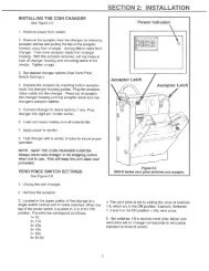
INITIAL SET-UPA. UNPACKINGRemove all plastic film, cardboard and tape from the outside of the vendor. Loosen anyshipping devices used to secure interior parts during shipment (backspacer, shims orspacers).To remove shipping boards from base, raise vendor on a well-stabilized lifting device.Remove the leveling bolts which hold the boards in place and remove the boards. Replacebolts to equal heights in the threaded holes. Another method to remove shippingboards is to split the boards apart. Using a pinch bar or a heavy screwdriver and hammer,insert tool into the slots and force the boards apart. The leveling legs shall notraise the vendor more than 1 1/8 inch above the ground.B. POSITIONINGIMPORTANT: PLACE THE VENDOR IN DESIRED LOCATION AT LEAST THREEINCHES (7.6CM) AWAY FROM ANY REAR OBSTRUCTION. This is for proper air flowthrough the refrigeration compartment. The refrigeration system requires rear to front aircirculation for proper operation.C. POWER SUPPLY CONNECTIONCAUTION: DO NOT USE AN EXTENSION CORD!The vendor’s power requirements will vary depending upon the country it was purchasedfor. To verify the power requirements of the vendor, check the serial plate locatedon the hinged side of the outer door (see Figure 4 on page G-4). The powerrequirements are listed on the serial plate.To insure safe operation of the vendor, the vendor’s power supply must be a properlygrounded and polarized outlet. Before plugging the vendor into the outlet, test the outletto confirm it will meet the vendor’s power requirements. If the power supply of the outletis different from the power requirements of the vendor, a transformer may be necessary.If the power requirements are not properly met, contact a licensed electrician and havethe necessary correction made.Should you require additional information, contact the Technical Services Department ofthe <strong>Vendo</strong> office in your area.G-307/2003
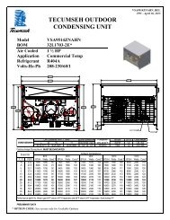
MODELSERIAL NO.APPROVED FOR OUTDOOR USEBASICUNITCHARGE OZ. R-134a AMPSDESIGN PRESSURE - PSIgLOW SIDE 90 HIGH SIDE 295REFRIGERATEDVENDING MACHINE239LMFD IN U.S.A. BY THE VENDO CO., FRESNO, CA.105/11550/601VOLTSCYCLEPHASEPOWER REQUIREMENTSFIGURE 1NOTE: The Model number of the vending machine is located on the top, left hand cornerof the serial plate. A typical model number could read “450VPV001”. The 450 is the modelnumber, VPV represents the product line of the vendor, and the remaining digits tell whatoptions are included.G-407/2003
FLAVOR STRIP INSTALLATIONInsert flavor labels to the top of selection window. A rear view of window is shown inFigure 2. The arrow points to the direction to insert labels.FIGURE 2ALIGNMENT CHECKFIGURE 3REFRIGERATION AREA CHECK:Check the position of the condensation pan (see Figure 3). The correct position of thepan is on the right hand side of the vendor with the ramp of the pan just outside theright hand air dam. Be sure the drain tube is attached to the pan and is free of kinks. Awater trap is installed into the condensation pan and will prevent warm, moist air fromreaching the evaporator area.G-507/2003
LOADING INSTRUCTIONSBASIC LOAD SET-UP (see Figure 4 on next page):The <strong>Vari</strong>-<strong>Pak</strong> machine is capable of vending a variety of products. For specific information,refer to the product set-up label on the machine inner door or contact the TechnicalServices Department of the <strong>Vendo</strong> office in your area.Use the directions in Figure 4 in the PRODUCT LOADING section to determine how toload a specific product.To maintain the integrity of the modules, never move a vending machine when it isloaded.VARI-PAK PRODUCT SETUP AND LOADING INSTRUCTIONS300 mLMODULE500 mLMODULESIZE125 mL200mL200 mL200 mL250 mL250 mL330 mL12 OZ250 mL500 mL16 OZ12 OZ12 OZDESCRIPTIONBRIKBRIKBRIK SLIMBRIK MID-SIZEBRIKPRISMAPRISMASTANDARDSTANDARDPRISMASTANDARDDASANI*AQUAFINA** LOAD CAP END FIRSTTYPEASEPTIC CARTONASEPTIC CARTONASEPTIC CARTONASEPTIC CARTONASEPTIC CARTONASEPTIC CARTONASEPTIC CARTONCANCANASEPTIC CARTONCANPET BOTTLEPET BOTTLESIDESPACER1125100NONE11251001125096NONE11251001125096NONE1125096NONENONENONENONECOLUMNSETTING4544545626666BACK SPACERPOSITIONSLEFT13NOT USEDNOT USEDNOT USEDNOT USEDNOT USEDNOT USEDNOT USEDNOT USEDNOT USEDNOT USEDNOT USEDRIGHT13NOT USEDNOT USEDNOT USEDNOT USEDNOT USEDNOT USEDNOT USEDNOT USEDNOT USEDNOT USEDNOT USEDSIDE SPACERS0.3"SIDESPACER0.6"SIDESPACER1125096 1125100BACK SPACERSBACK SPACERLOCATIONS(TWO LOCATIONSPER COLUMN)COLUMNSETTINGS1094 3 2 1151. PULL OUT MODULE.2. OPEN DOOR.3. INSERT PRODUCTINTO COLUMN.4. CLOSE DOOR.5. PUSH MODULE IN.PER MODULE)For questions regarding product settings not shown, contact the <strong>Vendo</strong> Technical Services Departmentat 1-800-344-7216 ext.3368 (US/Canada) or 559-439-1770 ext.3368.FIGURE 4SIDE SPACERLOCATIONS(SIX LOCATIONS87654321COLUMNSETTINGSARE MARKEDON MODULE(SETTING #3SHOWN)2G-6431125299(LEFT)1125299-1(RIGHT)07/2003
VEND MECHANISM PARTS DESCRIPTIONThe part listed below is the vend motor mechanism (refer to Figure 5 on this page). Threevend mechanisms are required per module. The parts are interchangeable. Settings willdiffer depending on product type and size.VEND MECHANISM ASSEMBLY: P/N 1124288The motor is attached to the module by screws.FIGURE 5G-707/2003
NOTESG-807/2003
VA R I - PA KCLEANING INFORMATIONSECTIONCL-107/2003
CARE AND CLEANINGDO NOT USE WATER JET FOR CLEANING.AVOID USING WATER OR ANY OTHER LIQUIDS NEARELECTRONIC COMPONENTSA. GENERAL PROCEDURE (painted metal areas)Wash the vendor with soap and water. The exterior may be waxed with any goodautomobile wax.B. FRESH PAINT SPLASHES, GREASE, GLAZING COMPOUND REMOVALBefore drying, these elements may be removed by rubbing lightly with grade“A” Naptha (or equivalent grade solvent). After removal, use general cleaningprocedure (listed above in A).C. LABELS AND STICKER REMOVALUse any specialized label removal liquid. When the label material does not allowpenetration of solvent (such as vinyl), the application of heat (ie – hot air gun) willsoften the adhesive and promote removal. CAUTION: Excessive heat can causesurface damage. After the label is removed, use the general cleaning procedure(listed above in A).D. SCRATCH REMOVALRemove or minimize hairline scratches and minor abrasions in painted surfaces byusing any good quality automobile polish. Test the polish before using.E. LEXAN SIGNSTo clean Lexan sign faces the following procedure is recommended.1. Wash sign with mild soap or detergent and lukewarm water.2. Using a soft cloth or sponge, gently wash the sign. DO NOT SCRUB!3. Rinse well with clean lukewarm water.4. Dry thoroughly with a chamois or cellulose sponge (to prevent waterspotting). DO NOT USE SQUEEGEE!NOTE: Most organic solvents, petroleum, spirits, or alcohol are NOT compatiblecleaning materials for Lexan signs. Usage of those materials couldpermanently damage the sign.F. REFRIGERATION AREAThe condenser and evaporator must be kept clean for efficient operation. Be sureall vanes and tubing are clean and clear of obstruction; this allows free passage ofair. Clean with a brush, a vacuum cleaner or compressed air, using extreme cautionnot to bend the condenser vanes. Keep cabinet drain open; clean as necessary.CL-207/2003
G. PRODUCT CHUTE, HOPPER, & OTHER INTERIOR SURFACES THAT CONTACTPACKAGED PRODUCTWash the surfaces with a mild food safe soap (i.e. Palmolive Liquid Dish Soap) &water. Rinse with plain water to remove any soap residue.Recommended Cleaning Schedule<strong>Vendo</strong>r AreaFrequencyProduct ChuteMonthly and when spills occurHopper/Delivery Port Weekly and when spills occurExterior Cabinet/Door Every 6 months or as neededSign FaceEvery 6 months or as neededCabinet Interior Every 6 months or as neededDoor InteriorEvery 6 months or as neededCondenserEvery 3 months or as neededEvaporatorAs requiredModulesEvery 6 months and when spills occurCL-307/2003
NOTESCL-407/2003
VA R I - PA K14.1 PROGRAMMINGSECTIONPG-107/2003
VEC 14.1 CONTROL BOARD OPERATIONThe VEC 14.1 controller operates via a 4-button programming system:Selection Button #1 – ReturnSelection Button #2 – Increase/Move ForwardSelection Button #3 – Decrease/Move BackwardSelection Button #4 - EnterIn order to access the mode functions, open the inner door. Locate the mode button.Press the mode button one time. Selection Button #2 will take you through the modes.The available modes are:DiagnosticsCoin PayoutTube FillTest ModeCash DataSales DataDiscount CounterFree CounterSet PriceConfigurationSpace to SalesDoor Closed PasswordSet LanguageSet Clock *Lighting *Refrigeration**Sales Block 1 *Sales Block 2 *Discount *Override **Custom MessageReturn* These modes will only appear when the Timing Features in Configuration are turnedON.** Limited options will appear in these modes depending on whether the Timing Featuresare ON/OFF.PG-207/2003
DiagnosticsSee attached error code chart on page PG-22 for errors and how to clear them.When you enter into the Diagnostics mode with selection button #4, the first one of thesummary error codes will be displayed. If no errors have occurred since the last error reset,the display will show an Error None message. Pressing selection button #2 (up) or selectionbutton #3 (down) will cycle through all of the summary error codes. Pressing selection button#4 will allow access into the detailed error code, while pressing selection button #1 returns tothe Diagnostics display.Coin PayoutAllows you to payout coin tubes.• Press selection button #4 to enter into Coin Payout mode.• Press selection button #2 (up) or selection button #3 (down) to choose denomination.• Press selection button #4 to dispense displayed denomination.• Press selection button #1 to exit mode.Tube FillAllows you to fill coin tubes via external coin insert. This is the recommended way to fill thecoin tubes because the control board is able to keep an accurate count of the coins.• Press selection button #4 to enter into Tube Fill mode.• Insert coins into coin insert slot and the controller will “count” the number of coins goinginto the coin mechanism.• Press selection button #1 to exit mode.Test ModeAllows you to test vend a column, selection switches, display, refrigeration relay, light relay,heater relay and evaporator fan relay.Test Mode - Vending• At Test mode, press selection button #4.• Display will read Test Mode – Vending.• Press selection button #4.• Display will read Test Mode – Vending; Column A1.• Press selection button #2 (up) or selection button #3 (down) to choose desiredcolumn.• Press selection button #4 to vend the displayed column.• If motor vends OK, display will read “Motor OK”• If motor does not test OK• Fail - Motor not Found will be displayedPG-307/2003
• Fail – Column Jam will be displayed if the motor is not in the homeposition and will not move.• Fail – No Connection will be displayed if the motor is disconnected.• Fail – High Current will be displayed if the motor has a short.Test Mode - Jog• At Test mode, press selection button #4• Press selection button #2 (up) or selection button #3 (down) until the display readsTest Mode - Jog• At Test Mode – Jog press selection button #4• Test Mode – Jog; Column A1&A2 will be displayed indicating that a jog test of thefirst column may be initiated.• Press selection button #2 (up) or selection button #3 (down) to choose desiredcolumn.• Press selection button #4 and Column nn&nn Forward will be displayed indicatinga forward motion of the motor.• Press selection button #2 (up) or selection button #3 (down) to toggle betweenForward and Reverse.• Pressing selection button #4 will initiate a jog test of the last displayed motor in thelast displayed direction. Please note that the jog will not be allowed to continue toa point, or in a direction, that will damage any part of the mechanism.• Press selection button #1 twice to return to the Test Mode – Jog display.Test Mode - Display• At Test mode, press selection button #4.• Press selection button #2 (up) or selection button #3 (down) until the display readsTest Mode – Display.• At Test mode – Display, press selection button #4• If functional, all 20 characters of the display should illuminate.• Press selection switch #1 to return to Test Mode – Display.Test Mode - Switches• At Test mode, press selection button #4.• Press selection button #2 (up) or selection button #3 (down) until the displayreads Test Mode – Switches.• Press selection button #4 and the display will read Test Mode – Switches;Selection ?• Activation of each selection button will display the selection switch number.• Press and hold selection button #1 for at least 2 seconds to return to Test Mode– Switches.Test Mode - RelaysAllows you to test compressor, fan, lights and heater via the relays.• At Test mode, press selection button #4.• Press selection button #2 (up) or selection button #3 (down) until the displayreads Test Mode - Relays• Press selection button #4.PG-407/2003
• To advance through sub-modes, press selection button #2 (up) or selection button#3 (down).• To test the compressor, press selection button #4 when the display readsCompressor Off.• Off will begin to flash.• Press selection button #2 (up) or #3 (down) to change Off to On.• Press selection button #4 and the compressor should turn on.• To turn the compressor off, press selection button #4 when the display readsCompressor On.• On will begin to flash.• Press selection button #2 (up) or #3 (down) to change On to Off.• Press selection button #4 and the compressor should turn off.• To test the optional evaporator fan relay, press selection button #4 when thedisplay reads Fan Off.• Off will begin to flash.• Press selection button #2 (up) or #3 (down) to change Off to On.• Press selection button #4 and the evaporator should turn on.• To turn the evaporator off, press selection button #4 when the display readsEvaporator On.• On will begin to flash.• Press selection button #2 (up) or #3 (down) to change On to Off.• Press selection button #4 and the evaporator should turn off.• To test the lighting system, press selection button #4 when the display reads LightOff.• Off will begin to flash.• Press selection button #2 (up) or #3 (down) to change Off to On.• Press selection button #4 and the lights should turn on.• To turn the lights off, press selection button #4 when the display readsLights On.• On will begin to flash.• Press selection button #2 (up) or #3 (down) to change On to Off.• Press selection button #4 and the lights should turn off.• NOTE: The lights will stay on during the rest of the programming if you do not turnthem off. This is to provide lighting during service work.• To test the optional heater, press selection button #4 when the display readsHeater Off.• Off will begin to flash.• Press selection button #2 (up) or #3 (down) to change Off to On.• Press selection button #4 and the heater should turn on.• To turn the heater off, press selection button #4 when the display reads HeaterOn.• On will begin to flash.• Press selection button #2 (up) or #3 (down) to change On to Off.• Press selection button #4 and the heater should turn off.PG-507/2003
• To exit the sub-modes, press selection button#1.Cash DataAllows you to retrieve historical information regarding the money accepted by the vendor.To clear the individual selection cash data, you must have the MIS Auto Reset in theConfiguration mode turned ON.• Press selection button #4 when the display reads Cash Data.• The non-resettable historical data is displayed.• To display resettable individual selections, press selection button #2 (up) orselection button #3 (down) until you reach the desired selection.• To reset historical data, make sure the MIS Auto Reset is turned ON in theconfiguration mode.• To exit mode, press selection button #1.Sales DataAllows you to retrieve historical information regarding the number of units sold by thevendor. To clear the individual selection sales data, you must have the MIS Auto Reset inthe Configuration mode turned ON.• Press selection button #4 when the display reads Sales Data.• The non-resettable historical data is displayed.• To display resettable individual selections, press selection button #2 (up) orselection button #3 (down) until you reach the desired selection.• To reset historical data, make sure the MIS data reset is turned ON in theConfiguration mode.• To exit mode, press selection button #1.Discount Counter(This item will only show when discounts are used.)Allows you to access the sales and cash data for vends that have been discounted.• Press selection button #4 when the display reads Discount Counter. The displaywill change to read Cash Data.• Press selection button #4 when the display reads Cash Data.• The display will change to read Cash Data Total and display the value of alldiscounts towards paid sales. This total is non-resettable and begins when thediscount feature is enabled.• Pressing selection button #2 (up) or selection button #3 (down) will scroll throughall of the selection buttons and display the value of the discounts toward productsales. The amounts for the individual selections can be reset using the rules inthe Configuration mode.• To exit this mode, press selection button #1.• The display will return to Discount Counter, Cash Data.PG-607/2003
• To advance to the sales information, press selection button #2 when the displayreads Discount Counter, Cash Data.• The display will change to Discount Counter, Sales Data. Press selection button#4 to access (enter) this information. The total number of discounted sales willbe displayed. This total is non-resettable and begins when the discount feature isenabled.• Pressing selection button #2 (up) or selection button #3 (down) will scroll throughall of the selection buttons and display each selection’s number of discounted sales.The amounts for the individual selections can be reset using the rules in theConfiguration mode.Free Counter(This item will only show if free vends during closed-door sales mode have been made.)Allows you to access the sales and cash data (loss) for vends that have been free.• Press selection button #4 when the display reads Free Counter. The display willchange to read Cash Data Total XX.XX. It will display the value of all lost moneybased on the price value setting. This total is non-resettable and begins when thefree vend override feature is enabled.• Pressing selection button #2 (up) or selection button #3 (down) will change to thesecond screen. The display will change to read Sales Data Total X. It will display thetotal number of free vends that have occurred. This total is non-resettable andbegins when the free vend override feature is enabled. Press selection button #1 toexit the mode.Set PriceAllows you to set the vend price of each selection. In this mode, you have the option of pricingeach selection button at the same vend price or price each selection button independently.• Press selection button #4 when the display reads Set Price.• Press selection button #2 (up) or selection button #3 (down) to toggle between allof the selections.• Press selection button #4 to start the current vend price flashing.• Press selection button #2 to increase the price.• Press selection button #3 to decrease the price.• Press selection button #1 to exit the mode.PG-707/2003
ConfigurationThere are various options in the configuration mode that you can turn ON/OFF. Theoptions are:Multi-PriceON = All selections can be programmed individually. Single price operation isdisabled.OFF = All selections will be set to the same price as selection 1. Single price operationis enabled.Timing Features*ON = Gives you access to the Clock settings and its associated modes.OFF = Clock settings and its associated modes are hidden.Door SummaryON = Sales, cash data and error status are displayed as soon as the outer door isopened or by activating the door switch.OFF = Sales and cash data are not displayed when the door is opened, but the errorsummary will be displayed.MIS Auto ResetON = After you check the sales and cash data, press the door switch and the individualselection data will be reset back to zero.OFF = Sales and cash data will not be reset by activating the door switch.Customer OverpayON = A dollar bill will be accepted even if the correct change light is on and there isinsufficient change in the coin tubes.OFF = A vend will not be allowed when the correct change light is on and the consumerattempts to use the dollar bill validator.Save Credit TmrON = Credit that is established will be displayed for five minutes unless someoneeither makes a vend or presses the coin return button – whichever comes first.OFF = Credit that is established will remain indefinitely unless someone either makesa vend or presses the coin return button.Force VendON = The consumer will not be able to insert a dollar into the validator, hit the coin returnand receive change without first attempting a vend. Change machine is disabled.OFF = The consumer can insert a bill into the validator, press the coin return buttonand immediately receive change. Change machine is enabled.PG-807/2003
Multi-VendON = The consumer may insert enough credit to make multiple vends. The credit will remainon the display until an additional vend is made or the coin return button is pressed.OFF = The consumer is only allowed to make a single vend and the credit (if applicable),will be returned after the completion of the vend.Deny EscrowON = The validator will stack all bills received.OFF = The validator will not stack the bills, rather it will hold them in escrow until a vendis complete.SO IndicatorON = A small symbol will appear in the lower right hand corner of the display when at leastone column is sold out or the machine detects an error.OFF = The symbol will not appear.Count by Selection/PriceCOUNT BY SELECTION = Individual sales and cash data will be reported in unit sales.COUNT BY PRICE = Individual sales and cash data will be reported by vend price.MIS Reset with DEXON = The resettable MIS data will be reset when a DEX read has been completed.OFF = The resettable MIS data will not be reset when a DEX read has been completed.*When the Timing Features are turned ON, you will have access to additional modes inthe programming relating to the internal timing and blocking functions.• To adjust any of the settings, press selection button #4 at Configuration mode.• Press selection button #2 (up) or selection button #3 (down) to scroll through thevarious sub-modes.• Press selection button #4 to change the status of the mode. The current setting willbegin to flash.• Press selection button #2 (up) or selection button #3 (down) to change the currentsetting.• Press selection button #1 to exit the mode.Space to SalesAllows you to program which column will vend when you choose a desired selectionbutton. There are 6 preset configurations (See Page PG-23). You also have the optionof customizing the space to sales. To change current setting:• Press selection button #4 at the Space to Sales prompt.• The current space to sales setting will be displayed.• Press selection button #4 to change the current setting.• Press selection button #2 (up) or selection button #3 (down) to toggle through thePG-907/2003
available settings.• Press selection button #4 to save the desired setting.• NOTE: Pressing selection button #1 before saving, will exit you from the Spaceto Sales mode without changing the current setting.• Press selection button #1 to exit mode.Custom Space to Sales Setting• Press selection button #4 at the Space to Sales prompt.• The current space to sales setting will be displayed.• Press selection button #4 to change the current setting.• Press selection button #2 (up) or selection button #3 (down) to toggle through theavailable settings until you reach Custom.• Press selection button #4 and the display will read Clear Setting?• Press selection button #4 to clear previous space to sales settings and unassign allcolumns and selection buttons – OR -• Pressing selection button #2 (up) or selection button #3 (down) to cycle through all theselections and Save Setting?.• Pressing selection button #4 at the desired selection will activate the change status.The display will show Sel n - XX where the X is blinking if the column is currentlyassigned to the selection n.• Using selection button #2 (up) or selection button #3 (down) will cycle through allavailable columns.• Press selection button #4 to change the status. If XX is blinking, the column is assignedto the displayed selection. If XX is steady/not blinking, the column is not assigned tothe displayed selection.• NOTE: Pressing selection button #1 will exit you from the custom space to sales modeand display Save Setting? Be sure to press selection button #4 at Save Setting? if youwould like the changes to be made.• The display will return to Custom once selection button #4 is pressed.• Press selection button #1 to exit the mode and return to the Space to Sales prompt.Door Closed PasswordAllows you to set a password to access sales data only when the door is closed. Pleasenote that this function will not work if the vend price is set at 0.00.• Press selection button #4 at Door Closed Password mode.• The current password will be displayed with the first digit flashing indicating that itis ready to be edited.• Pressing selection button #2 (up) or selection button #3 (down) will allow you tochange the digits. NOTE: Valid digits are 0 through 6. Any password with 0 willdisable this feature.• Press selection button #4 to advance to the next digit.• Press selection button #4 after the 4 th digit to exit the mode.PG-1007/2003
Set LanguageAllows you to program different languages on the controller. The current languages availableare English, Spanish and French.• Press selection button #4 at the Set Language mode.• The current language will be displayed.• To change current language, press selection button #4 to start the language flashing.• Press selection button #2 (up) or selection button #3(down) to choose a language.• Press selection button #4 to save the language change.• Press selection button #1 to exit mode.Set ClockIf the Timing Features in the Configuration mode are turned ON, you will have access to thismode. This mode allows you to set the current month, day, year, hour and minute.To set the clock:• Press selection button #4 at the Set Clock prompt. You will be able to scroll throughthe following options by pressing selection button #2 (up) or selection button #3(down).• Enable ON/OFF - This will turn the clock timer on or off.• MM/DD/YYYY HH:MM - This is the current time & date.• Daylight Savings – OFF, North American, Europe or Australia• To change current setting, press selection button #4.• The current setting will begin to flash.• Press selection button #2 (up) or selection button #3 (down) to change currentsetting• Press selection button #4 to save the current setting.• Press selection button #1 to exit the mode.LightingIf the Timing Features in the Configuration mode are turned ON, you will have access tothis mode. This mode allows you to turn the lights on/off with the internal timer for energyconservation. You have the ability to turn the lights off at two different intervals during theday.• Press selection button #4 when the display reads Lighting• Press selection button #4 at Enable On/Off.• To change the status of the lights, press selection button #2 (up) or selection button#3 (down) to toggle between On/Off.• Press selection button #4 to change the status.• Press selection button #2 to advance to Start Time 1. This is the time that the lightsPG-1107/2003
will turn off or begin the light conservation.• Press selection button #4 at Start Day 1.• Scroll through the days of the week or Every Day with selection button #2 (up) orselection button #3 (down).• To change the current setting, press selection button #4.• On/Off will begin to flash.• Press selection button #2 (up) or selection button #3 (down) to toggle betweenOn/Off.• Press selection button #4 to save the current setting.• Press selection button #1 to return to Start Day 1.• Press selection button #2 (up) to advance to Start1 hh:mm.• Press selection button #4 at Start1 hh.mm to set the time for the light energyconservation mode to begin.• Press selection button #2 (up) or selection button #3 (down) to change the hour.• Press selection button #4 to advance to the minutes.• Press selection button #4 to save the displayed time.• Press selection button #1 to exit the mode and return to Start Time 1.• Press selection button #2 (up) to advance to Stop Time 1.• Repeat process with Stop Time 1.RefrigerationIf the Timing Features in the Configuration mode are turned OFF, you will only haveaccess to the following two modes:Set PointSensor ReadingDegree X – Celsius or FahrenheitFan Disable/EnablePeriodic Defrost – On/OffIf the Timing Features in the Configuration mode are turned ON, you will have additionalaccess to the following modes:EnableStart Time 1 & 2Start Day 1 & 2Start 00:00Stop Time 1 & 2Stop Day 1 & 2Stop 00:00This mode allows you to turn the refrigeration on/off with the internal timer for energyconservation. You have the ability to raise the temperature of the refrigeration system 18°Fat two different intervals during the day.PG-1207/2003
• Press selection button #4 when the display reads Refrigeration.• The display will read Setpoint.• Press selection button #4 and the display will read the current setpoint temperature.NOTE: The machine is set at 36°F from the factory.• Press selection button #4 and the temperature will begin to flash.• Pressing selection button #2 (up) or selection button #3 (down) will cycle youthrough the following settings:Cut-in Temperature (F) 34 35 36 37 38 39 40 41 42Cut-out Temperature (F) 30 31 32 33 34 35 36 37 38Nominal Temperature (F) 32 33 34 35 36 37 38 39 40Nominal Temperature (C) 0 0.5 1.0 1.5 2.0 2.5 3.0 3.5 4.0• Press selection button #4 to save the setting.• Press selection button #1 to return to the Setpoint mode.• Press selection button #2 (up) to advance to the next submode.• Press selection button #4 to access the temperature reading.• Press selection button #1 to exit this mode.• Press selection button #2 (up) to advance to the next submode.• The display will show the current degree scale F or C (Fahrenheit or Celsius).• Press selection button #4 to change the current setting.• Use selection button #2 (up) or selection button #3 (down) to toggle between Celsiusor Fahrenheit.• Press selection button #4 to save the setting and exit the mode.• Press selection button #2 (up) to advance to the next submode.• Press selection button #4 to access the Fan X mode.• Fan Disable = The evaporator fan will be turned off/on with the activation of thecompressor.• Fan Mode 1 = The evaporator fan will turn off 5 minutes after the compressor fanis turned off. When the compressor is turned on, the evaporator will turn on at thesame time.• X will be flashing.• Press selection button #2 (up) or selection button #3 (down) to toggle betweenDisable/Mode 1/Mode 2.• Press selection button #4 to save the setting.• Press selection button #1 to exit this mode.• Press selection button #2 (up) to advance to the Periodic Defrost mode.• On/Off will be flashing.• Press selection button #2 (up) or selection button #3 (down) to toggle between On/Off.PG-1307/2003
• On = The machine will defrost every 6 hours – for 30 minutes. This is forextremely high humidity environments.• Off = Machine will not defrost every 6 hours.• Press selection button #4 to save the setting.• Press selection button #1 to exit this mode.• Press selection button #2 (up) to advance to the next submode – Enable Timer.• Press selection button #4 to access the Fan energy conservation mode.• Press selection button #4 at Enable Timer On/Off.• To change the timer status, press selection button #2 (up) or selection button #3(down) to toggle between On/Off.• Press selection button #4 to save the status.• Press selection button #2 to advance to Start Time 1. This is the time that thetemperature will raise to begin the energy conservation.• Press selection button #4 at Start Day 1.• Scroll through the days of the week or Every Day with selection button #2 (up) orselection button #3 (down).• To change the current setting, press selection button #4.• On/Off will begin to flash.• To change the status, press selection button #2 (up) or selection button #3(down) to toggle between On/Off.• Press selection button #4 to save the status.• Press selection button #1 to return to Start Day 1.• Press selection button #2 (up) to advance to Start 1 hh:mm.• Press selection button #4 at Start 1 hh.mm to set the time for the refrigerationconservation mode to begin.• Press selection button #2 (up) or selection button #3 (down) to change the hour.• Press selection button #4 to save the displayed hour and advance to the minutes.• Press selection button #2 (up) or selection button #3 (down) to change theminutes.• Press selection button #1 to exit the mode and return to Start Time 1.• Repeat process with Stop Time1.Sales Block 1 and 2Allows you to program the machine to turn off and on at regular intervals. You have theability to turn the machine off/on at two intervals during the day.To program the blocking feature, you must enter the following information:Selections – the selection buttons that will be disabled during the blocked timeStart Time – the time that the machine will turn off/shut downStart Days – the days that the machine will turn off/shut downStop Time – the time that the machine will turn back onStop Days – the days that the machine will turn back onPG-1407/2003
To choose the selections:• Press selection button #4 when the display reads Sales Block 1 or 2.• The display will read Enable X• Enable Off = The block function is off/disabled/inactive• Enable On = The block function is on/enabled/active• Enable Light = The block function is on and the lights are off when blocking occurs.• To change the Enable status, press selection button #4.• Use selection button #2 (up) or selection button #3 (down) to cycle through the availableoptions.• Press selection button #4 to save the status change and return to the Enable submode.• Press selection button #2 (up) to advance to Selections.• Press selection button #4 to change the status of the selection buttons during the blockingmode.• Press selection button #2 (up) or selection button #3 (down) to cycle through the availableselections or All Selections.• Press selection button #4 to change the status of the selections. If the status is On, theselections will be disabled during the blocked time(s). If the status is Off, the selections willremain enabled during the blocked time(s).• Press selection button #2 (up) or selection button #3 (down) to toggle between On/Off.• Press selection button #4 to save the setting.• Press selection button #1 to return to Selections.To set the start time• Press selection button #2 (up) when the display reads Selections.• Press selection button #4 when the display reads Start Time.• Press selection button #4 when the display reads Start Day.• Press selection button #2 (up) or selection button #3 (down) to cycle through the days orEvery Day.• Press selection button #4 to change the status of the days. If the status is On, the days willbe disabled during the blocked time(s). If the status is Off, the days will remain enabledduring the blocked time(s).• Press selection button #2 (up) or selection button #3 (down) to toggle between On/Off.• Press selection button #4 to save the setting.• Press selection button #1 to return to Start Day.• Press selection button #2 (up) to advance to Start hh:mm.• Press selection button #4 and the hour setting will begin to blink indicating that it is readyto be edited.• Press selection button #2 (up) or selection button #3 (down) to choose the desired starthour. The time is in a 24-hour format.• Press selection button #4 and the minutes will begin to flash.• Press selection button #2 (up) or selection button #3 (down) to choose the desired startminutes.• Press selection button #4 to save your settings.• Press selection button #1 to return to Start Time.PG-1507/2003
To set the stop time• Press selection button #2 (up) when the display reads Start Time.• Press selection button #4 when the display reads Stop Time.• Press selection button #4 when the display reads Stop Day.• Press selection button #2 (up) or selection button #3 (down) to cycle through the daysor Every Day.• Press selection button #4 to change the status of the days. If the status is On, the dayswill be disabled during the blocked time(s). If the status is Off, the days will remainenabled during the blocked time(s).• Press selection button #2 (up) or selection button #3 (down) to toggle between On/Off.• Press selection button #4 to save the setting and exit the submode.• Press selection button #2 (up) to advance to Stop hh:mm.• Press selection button #4 and the hour setting will begin to blink indicating that it isready to be edited.• Press selection button #2 (up) or selection button #3 (down) to choose the desiredstop hour. The time is in a 24-hour format.• Press selection button #4 and the minutes will begin to flash.• Press selection button #2 (up) or selection button #3 (down) to choose the desiredstop minutes.• Pressing selection button #4 will save your settings.• Press selection button #1 to return to Stop Time.• Pressing selection button #1 again, will return you to the Sales Block 1 or 2 mode.DiscountAllows you to program the machine to discount beverages at regular intervals.To program the Discount feature, you must enter the following information:Discounted Selection – The selections to be offered at a discounted price.Start Time – The time that the discount begins.Start Day – The days that the discount is offered.Stop Time – The time that the discount ends.Stop Day – The days that the discount ends.Amount - The amount subtracted/discounted from the original vend price.To set the discounted selections• Press selection button #4 when the display reads Discount.• The display will read Enable X• Enable Off = The discount function is off/disabled/inactive• Enable On = The discount function is on/enabled/active• To change the Enable status, press selection button #4.• Use selection button #2 (up) or selection button #3 (down) to cycle through theavailable options.PG-1607/2003
• Press selection button #4 to save the status change and return to the Enable submode.• Press selection button #2 (up) to advance to Discounted Selection.• Press selection button #4 to change the status of the selection buttons during the discountmode.• Press selection button #2 (up) or selection button #3 (down) to cycle through the availableselections or All Selections.• Press selection button #4 to change the status of the selections. If the status is On, theselections will be discounted during the established time. If the status is Off, the selectionswill not be discounted during the established time.• Press selection button #2 (up) or selection button #3 (down) to toggle between On/Off.• Press selection button #4 to save the setting.• Press selection button #1 to return to Discounted Selection.To set the start time• Press selection button #2 (up) when the display reads Discounted Selection.• Press selection button #4 when the display reads Start Time.• Press selection button #4 when the display reads Start Day.• Press selection button #2 (up) or selection button #3 (down) to cycle through the days orEvery Day.• Press selection button #4 to change the status of the days. If the status is On, the days willbe enabled during the discount time. If the status is Off, the days will be disabled duringthe discount time.• Press selection button #2 (up) or selection button #3 (down) to toggle between On/Off.• Press selection button #4 to save the setting.• Press selection button #1 to return to Start Day.• Press selection button #2 (up) to advance to Start hh:mm.• Press selection button #4 and the hour setting will begin to blink indicating that it is readyto be edited.• Press selection button #2 (up) or selection button #3 (down) to choose the desired starthour. The time is in a 24-hour format.• Press selection button #4 and the minutes will begin to flash.• Press selection button #2 (up) or selection button #3 (down) to choose the desired startminutes.• Pressing selection button #4 will save your settings.• Press selection button #1 to return to Start Time.To set the stop time• Press selection button #2 (up) when the display reads Start Time.• Press selection button #4 when the display reads Stop Time.• Press selection button #4 when the display reads Stop Day.• Press selection button #2 (up) or selection button #3 (down) to cycle through the days orEvery Day.• Press selection button #4 to change the status of the days. If the status is On, the days willbe enabled during the discount time. If the status is Off, the days will be disabled duringPG-1707/2003
the discount time.• Press selection button #2 (up) or selection button #3 (down) to toggle between On/Off.• Press selection button #4 to save the setting.• Press selection button #1 to return to Stop Day.• Press selection button #2 (up) to advance to Stop hh:mm.• Press selection button #4 and the hour setting will begin to blink indicating that it isready to be edited.• Press selection button #2 (up) or selection button #3 (down) to choose the desiredstop hour. The time is in a 24-hour format.• Press selection button #4 and the minutes will begin to flash.• Press selection button #2 (up) or selection button #3 (down) to choose the desiredstop minutes.• Pressing selection button #4 will save the settings.• Press selection button #1 to return to Stop Time.To set the discount• Press selection button #2 (up) when the display reads Stop hh:mm.• Press selection button #4 when the display reads Amount $.• Use selection button #2 (up) or selection button #3 (down) to change the discountedamount.• Press selection button #4 to save the amount.• Pressing selection button #1 will return you to the Discount mode.OverrideThis feature is used in conjunction with an optional override key switch and harness.You must program a Start Time and a Start Time in the desired mode in order forthe key switch to operate. The key switch will only be active during the programmedtimes. The following features can be activated/deactivated with the key switch:Free Vend, Sales Blocking, Discount, Light Timing and Refrigeration.To activate the override features• Press selection button #4 when the display reads Override.• Press selection button #2 (up) or selection button #3 (down) to cycle through theavailable submodes.• Press selection button #4 to change the status – On/Off – of the submodes.• On = key switch will override pricing, blocking, discounting, lighting orrefrigeration.• Off = No change in pricing, blocking, discounting, lighting or refrigeration.• Press selection button #2 (up) or selection button #3 (down) to alternate betweenOn/Off.• Press selection button #4 to save the setting.• Press selection button #1 to return to Override.PG-1807/2003
Custom MessageThis feature provides the customer the ability to customize their welcome message on thevending machine. The display has a 20-character capacity on two lines for a total of 40characters. The message will not be shown if the feature is disabled.To set the custom message• Press selection button #4 when the display reads Custom Message.• The display will read Enable X.• Enable On = Custom message will be displayed.• Enable Off = Custom message will not be displayed.• To change the status, press selection button #4.• Press selection button #2 (up) or selection button #3 (down) to toggle between On/Off.• Press selection button #4 to save the change.• Press selection button #2 at Enable X and the current message will be displayed.• Press selection button #4 to change the current message. “a “ will be displayed if noprevious message had been set.• Press selection button #2 (up) or selection button #3 (down) to cycle through the availablecharacters.• Press selection button #4 to save the character and advance to the next character. Bydefault, every other position will change to “a” during the programming. This is becausethe lower case “a” is located in a central location between all usable characters.• Usable characters – “!”#$%&’()*+,-./0123456789:;?@ABCDEFGHIJKLMNOPQRSTUVWXYZ[\]^_`abcdefghjklmnopqrstuvwxyz{|}~”• Selection button #1 will be used as a space bar unless it is pressed and held for 2 seconds.After the 2 seconds, the unwanted space will go back to the value that was there and themessage will be saved.• Pressing selection button #1 will also return to Custom Message.ReturnExits the programming mode and returns the machine to stand-by.• Press selection button #4 when the display reads Return. The control board will be in anopen door standby mode until the door switch is activatedPG-1907/2003
VEC 14.1 WIRING DIAGRAMMODULE E MODULE D MODULE C MODULE BMODULE AG G G V R B Y YRN RN RN I E LK E EO D L LYEL10 9 8 7 6 5 4 3 2 1 10 9 8 7 6 5 4 3 2 1 10 9 8 7 6 5 4 3 2 1 10 9 8 7 6 5 4 3 2 1 10 9 8 7 6 5 4 3 2 110 9 8 7 6 5 4 3 2 1 10 9 8 7 6 5 4 3 2 1 10 9 8 7 6 5 4 3 2 1 10 9 8 7 6 5 4 3 2 1 10 9 8 7 6 5 4 3 2 1BLUWHTVIOBRNYELBLK/WHTBLKREDGRYORNRED/WHTORN/WHTB T PL A NK N K/WHTY B BE R LL N U1 1 1V W BI H LO T U2 2R Y BE E RD L N2 2V O GI R RO N Y11 2 3 4 5 6 7 8 9 10 11 121 2 3 4 5 6 7 8 9 10 11 12Y VE IL OGRYRED/WB BL LK U/WBRNORNREDORN/WBLKWHTCABINET COLDDOORJUNCTION LOCATEDIN WARM CABINETSELECTION SWITCHESDISPLAYSEL. # 1NO PNKCOM YELSEL. # 2PNKBRNSEL. # 3PNKVIOSEL. # 4PNKORNSEL. # 5PNKGRYSEL. # 6BLUYELSEL. # 7BLUBRNSEL. # 8BLUVIOSEL. # 9BLUORNSEL. # 10BLUGRY1GRNREDWHTBLK4GRN (SHIELD)H HT T1 12 23 3 YEL4 4 VIO5 5 GRY6 6 PNK7 7 WHT8 89 910 1011 1112 1213 13 BRN14 14 ORN15 1516 16 BLU17 1718 1819 1920 20DS/WHTCOMDOORSWITCHNC NODS/WHTHTGRNBLKJ25678123412 J113WHTREDJ311 112 2BRN 13 3 YELORN 14 4 VIORED 15 5 GRYBLU 16 6 PNKORN/WHT 17 7 RED/WHTBLK 18 8 BLK/WHTWHT 19 9 BLU20 107 18 29 3 J1010 4WHT11 512 6WHTJ9B B Y O GL R E R R1 K N L N N 6MDB SOCKETJ914 13 12 117 6 5 4G O YR R EN N L6 5 43 2 1B BR LN K1039281VEC 14.1CONTROLBOARDMODE SWITCHJ1ADEXSOCKETORN 4 3GRNORN 1 2 GRNJ5J6VIO1 C5-C6 9 1 BLU1 A1-A2BRN2 D1-D2 10 2 BRN1 A3-A4YEL2 D3-D4 11 3 YEL1 A5-A6RED D5-D6 12 4 PINK B1-B2BLU2 E1-E2 13 5 TAN B3-B4WHT E3-E4 14 6 BLK/WHT B5-B6VIO2 E5-E6 15 7 GRY C1-C2BLK/MCOM 16 8 ORN C3-C4J7WHT/CS 10 1 24V/GRYBRN/TS1 11 2 HEATER/VIOBRN/TS1 12 3 COMP/BLUWHT/VS1S 13 4 FAN/YELSHIELD/VS1R 14 5WHT/VS2S 15 6 LIGHTS/PNKSHIELD/VS2R 16 7TAN/TS2 17 8TAN/TS2 18 9 CS/WHT10 95 4J8837 62 1LIGHTING SYSTEM:SEE BALLAST FORWIRING DIAGRAMPG-2007/2003
VEC 14.1 WIRING DIAGRAM (CONTINUED)8 7 6 5 4 3 2 1 8 7 6 5 4 3 2 1 8 7 6 5 4 3 2 1GRNBLKYELFRONTMOTORR VE ID OGRNBLKYELMIDDLEMOTORR VE ID OGRNBLK(TYPICAL FOR EACH MODULE)YELBACKMOTORJUNCTION LOCATEDIN WARM CABINETR VE ID OE6BACKMOTORE5E4MIDDLEMOTORE3E2FRONTMOTORE1MODULEED6BACKMOTORD5D4MIDDLEMOTORD3D2FRONTMOTORD1MODULEDC6BACKMOTORC5C4MIDDLEMOTORC3C2FRONTMOTORC1MODULECB6BACKMOTORB5B4MIDDLEMOTORB3B2FRONTMOTORB1MODULEBMODULE & COLUMN CONFIGURATIONA6BACKMOTORA5A4MIDDLEMOTORA3A2FRONTMOTORA1MODULEACABINET COLDDOORBRNBRNTANTANGRNBLKWHT1 12 23 34 45 56 67 78 89 910 10 BRN211 11 YEL212 12 RED13 1314 1415 1516 1617 1718 1819 1920 2021 2122 2256781234123412341234GRN1 12 23 34 4123456123456BLKWHT/VS1SSHIELD/VS1RWHT/VS2SSHIELD/VS2RTEMPSENSOR 1(REFRIG.)VS1VENDSENSORSVS2CABINET COLDCABINET WARMPOWERPNK (6)BLKCORDLORN (5)WHTNORN (7)24GVAC2424 VACVACCTRANSFORMERGRNLIGHTPLAIND ABINETRELAYW COMPPRIMARYRELAYO ARMOR1 12 2BLU1BRN1YEL1PNKTANBLK/WHTGRYORNVIO1BLU2WHTVIO2WHTWHTBLKWHT/VS1SHIELD/VS1WHT/VS2SHIELD/VS2POWER DIST. BOX5678BLKWHTWHTYEL (4)VIO (2)BLU (3)GRY (1)BLKCS/WHTNCNO CABINETSWITCHCOMCS/WHTPNKBLKGRYGRYBLK3 41 21 23 4WHTBLKWHTBLKYELGRY (1)YEL (2)FUSE0.8 AMPSLOW BLOWBLUBLKRIBBED2 12 1WHTBLK3 41 23 41 2GRYBLKEVAP. FANMOTORMPLAINOPTIONALFANRELAY24VACGRYVIOWHTBLKBLKWHT1 12 23 34 4LNPLAINRIBBEDCOMP.PLUGCOND. FANMOTORMOVERLOADCABINET COLDCABINET WARMSTARTRELAYRIBBEDCAPACITOR(110 VOLTUNITS ONLY)REFRIGERATIONSYSTEMPG-2107/2003
Error Codes(sub-codes indented)NoneVend Mech ErrorColumn Jam XXVend Sensor ErrorVend Sensor 1Vend Sensor 2System ErrorCabinet SwitchDoor SwitchRAMA/C LowEscrow Return Mech.Scaling FactorInlet SensorInlet BlockedSelect Switch ErrorSelection XXSpace to Sales Column ErrorUnassigned Column XXSpace to Sales Selection ErrorUnassigned Selection XXChanger ErrorNo CommunicationTube SensorCoin InletTube XX JammedChecksumExcessive EscrowsCoin JamLow AcceptanceDisconnectedCoin RoutingBill Validator ErrorNo CommunicationStacker FullMotor ErrorJammedChecksumStacker OpenSensorCard Reader ErrorNo CommunicationCode XYRefrigeration ErrorSensorToo ColdToo HotNot CoolingNot HeatingVEC 14.1 Diagnostics Error CodesDescriptionNo error existVend mechanism summary errorColumn jam in column XXVend mechanism summary errorVend Sensor ErrorVend Sensor ErrorControl system summary errorCabinet switch open for more than 1 hourDoor switch open for more than 1 hourRAM check sum of service mode settingsA/C supply lowEscrow return mech. errorScale factor incompatibility<strong>Vendo</strong>r inlet coin chute sensor is blocked<strong>Vendo</strong>r inlet coin chute is blockedSelection switch summary errorSelection switch error in switch XXSpace to sales summary errorUnassigned columnSpace to sales summary errorUnassigned selectionChanger summary errorNo changer communicationTube sense errorChanger inlet chute blockedTube payout jam in coin type XXChanger ROM check sum errorExcessive escrow attemptsCoin jamAcceptance rate below 80%Disconnected acceptorCoin routing errorBill validator summary errorNo bill validator communicationBill validator stacker fullDefective bill validator motorBill validator jammedBill validator ROM check sum errorBill validator stacker is open or out of positionBill validator sensor errorCard reader summary errorNo card reader communicationCard reader non-transient error; code X, subcode YRefrigeration summary errorTemperature sensor defective or unpluggedCabinet temperature 3°F below low limitCabinet temperature 3°F above high limitCooling system not coolingHeating system not heatingPG-22Error codes are cleared by pressingselection button # 4 for 2 sec. when displayed,or automatically by the following activities:Complete a test vend cycle for column XXCheck or replace vend sensor assemblyCheck or replace vend sensor assemblyCabinet switch closure detectedDoor switch closure detectedChange any service mode settingCheck or replace escrow return mech assemblyScale factor correctedBlockage removedCoin detected by changerSelection switch opensColumn is assignedSelection is assignedProper communication receivedChanger correctedA coin is sensedChanger correctedChanger correctedA valid coin is sensedA coin is sensedAcceptance rate above 80%Acceptor properly connectedCoin is routed properlyProper communication receivedReceive stacker commandValidator becomes enabledValidator becomes enabledValidator becomes enabledValidator becomes enabledValidator becomes enabledProper communication receivedError stops being reportedSensor detectedTemperature rises above low limitTemperature falls below high limitSystem cools 1°F per hourSystem heats 1°F per hour07/2003
VEC 14.1 PRE - PROGRAMMED SPACE - TO - SALESSEL #1A1, A2, A3A1 - A6A1 - A6A1, A2, A32A4, A5, A6B1 - B6B1, B2, B3A4, A5, A63B1, B2, B3C1, C2, C3B4, B5, B6B1, B2, B34B4, B5, B6C4, C5, C6C1, C2, C3B4, B5, B65C1, C2, C3D1, D2C4, C5, C6C1, C26C4, C5, C6D3, D4D1, D2, D3C3, C47D1, D2, D3D5, D6D4, D5, D6C5, C68D4, D5, D6E1, E2E1, E2D1, D29E1, E2, E3E3, E4E3, E4D3, D410E4, E5, E6E5, E6E5, E6D5, D6OPTION 1OPTION 2OPTION 3OPTION 4CUSTOM SPACE TO SALESMODULE CONFIGURATIONE6E5E4E3E2E1D6D5D4D3D2D1C6C5C4C3C2C1B6B5B4B3B2B1A6A5A4A3A2A1*MODULE E MODULE D MODULE C MODULE B MODULE A*ONLY PRESENT ON MODEL 450PG-2307/2003
NOTES1. If the outer door is left open for over an hour, the lights and compressor willbecome active. In order to over-ride this option, press the door switch one time.PG-2407/2003
VA R I - PA KCABINET PARTSSECTIONC-107/2003
READING A PARTS LISTIIIIIIIVVITEM NUMBER is found in two locations:A. It is on the drawing plate, and identifies the part and its location;B. The same number is in the parts lists and ties the two together.PART NUMBER is the part number that has been assigned to a specific part by<strong>Vendo</strong>, for easier identification.QUANTITY REQUIRED relates to the amount required of a part, or will beindicated by “A/R” (as required) to attach it to another part.PART NAME AND DESCRIPTION is the general description for the part, foreasier identification when ordering a like part.HARDWARE is identified by a letter in a hexagon. Refer to hardware list sectionor description and part numbers. See pages C-4 and C-5.The example below will show how the parts are listed in the parts lists:1. TEMPERATURE SENSOR ASSEMBLY: This is the main assembly name, andany replaceable parts will be indented below the assembly.2. TEMPERATURE SENSOR: This is an individual part, and will be indented.These indented parts can be ordered separately, so you do not need to order theentire assembly.3. Whenever an assembly is ordered, all the parts that are indented will be includedin the assembly. Any hardware will be listed next to their corresponding parts.4. Any parts that may be ordered separately will not have any indented parts listedbelow them.ITEMNODESCRIPTIONQTYREQPART NO.1 TEMPERATURE SENSOR ASSEMBLY 1 11242542 TEMPERATURE SENSOR 1 11229243 TEMPERATURE SENSOR BRACKET 1 1124156If an asterisk is listed below the parts list, it is an indication that special information isnoted. There may be more than one asterisk (*) (**) (***) denoting special notes.C-207/2003
HARDWARE LISTC-307/2003
C-407/2003
C-507/2003
C-607/2003
VARI-PAK CABINET ASSEMBLYITEM NO. DESCRIPTION QTY REQ PART NO.1 CABINET ASSEMBLY - FOAMED 1 *2 SIDE DECAL A/R **3 INNER DOOR HINGE 2 11235024 LATCH BRACKET 3 11257555 PRODUCT CHUTE ASSEMBLY (SEE PAGES C8-C9) 1 ~6 FRONT STRAP ASSEMBLY 1 11258437 MODULE GUIDE BEARING *** 10162378 PRODUCT DEFLECTOR 1 11249289 POWER BOX ASSEMBLY (SEE PAGES C10-C11) 1 ~10 AIR DAM / KICK PLATE 1 112344011 LEVELING LEG 1 105990212 FIBERGLASS EVAPORATOR BOARD 1 112272813 CONDENSATE PAN 1 112247514 DRAIN TUBE 1 1088449-115 DRAIN TUBE NUT 1 38792516 DRAIN TUBE GASKET 1 38783717 DRAIN TUBE FUNNEL 1 106867818 BRACKET - REFRIGERATION 2 112352719 SAFETY SCREEN 1 112256820 CABINET GUARD 1 1124060-221 RAMP 1 112038722 COUNTERWEIGHT ASSEMBLY 1 112181223 SHROUD EXTENSION 1 112509924 CABINET HARNESS (NOT SHOWN) 1 112440125 GUIDE, MODULE STOP 1 112417726 MODULE STOP (MODEL 450 ONLY)MODULE STOP (ALL OTHER MODELS)* NOTE: WHEN ORDERING CABINET ASSEMBLY, PLEASE PROVIDE 9-CODE OR 11-CODE ANDMANUFACTURER’S DATE CODE.** NOTE: WHEN ORDERING DECALS, PLEASE PROVIDE STYLE.***NOTE: QUANTITY OF MODULE GUIDE BEARINGS IS EQUAL TO THE NUMBER OFMODULES IN YOUR STACK.431076317112527127 DEADBOLT HASP 2 1125769C-707/2003
C-807/2003
VARI-PAK PRODUCT CHUTE ASSEMBLYITEM NO. DESCRIPTION QTY REQ PART NO.1 PRODUCT CHUTE ASSEMBLY ~ 11257292 VEND SENSOR ASSEMBLY 1 11229233 FOAM PAD 2 11236544 MOUNTING BRACKET, VEND SENSOR 1 11236015 PRODUCT CHUTE 1 11257336 BRACKET, PRODUCT CHUTE 1 1125098-17 LINER, PRODUCT CHUTE 1 11257318 SPLASH GUARD, PRODUCT CHUTE 1 1125732C-907/2003
C-1007/2003
VARI-PAK POWER BOX ASSEMBLYITEM NO. DESCRIPTION QTY REQ PART NO.1 POWER BOX HOUSING ASSEMBLY, U.S.POWER BOX HOUSING ASSEMBLY, INTERNATIONAL11112344811258152 RELAY 2 11242843 CLAMP 1 324099-34 CORDSET, U.S. 110VCORDSET, DENMARKCORDSET, SWITZERLANDCORDSET, ITALYCORDSET, AUSTRALIACORDSET, UKCORDSET, CONTINENTAL EUROPE5 TRANSFORMER, U.S. 110VTRANSFORMER, INTERNATIONAL, CE1111111111124281112164611216451121644112164311216421121641111120111219326 FUSEHOLDER 1 3879667 0.8 AMP FUSE (NOT SHOWN) 1 10538648 FUSE LABEL 1 10895469 POWER HARNESS (NOT SHOWN) 1 1123444C-1107/2003
C-1207/2003
ITEMNO.VARI-PAK LEFT MODULE ASSEMBLYDESCRIPTIONQTYREQPART NO.330mLPART NO.500mL1 MODULE HANGER 1 1124055 11240552 OUTER / MIDDLE SLIDE 2 1124181-1 1124181-13 HARNESS GUIDE ASSEMBLY 1 1124852 11248524 INNER MEMBER, SLIDE 2 1124181-2 1124181-25 FRONT COVER - MODULE 1 1124180 11241806 MODULE TOP 1 1125254 11252537 MODULE LABEL 1 1124922 1124922-18 HANDLE 1 1124168 11241689 MODULE GUIDE 1 1125252 112525210 MODULE BODY 3 1125291 112426211 HOUSING - VEND MECHANISM 3 1125292 112426312 SUPPORT BRACKET - VEND MECHANISM 3 1124753 1124753-113 VEND MECHANISM 3 1124288 112428814 FRONT STRAP 1 1124044 112404415 DOOR ASSEMBLY - RIGHT 3 1125160 112516016 DOOR ASSEMBLY - LEFT 3 1125160-1 1125160-117 MODULE TOP BRACKET (500mL ONLY) 1 ~ 112426518 BUMPER (MODULE CLOSEST TO HINGE ONLY) 2 1036912 103961219 MODULE HARNESS (NOT SHOWN) 1 1124289 1124289C-1307/2003
C-1407/2003
ITEMNO.VARI-PAK RIGHT MODULE ASSEMBLYDESCRIPTIONQTYREQPART NO.330mLPART NO.500mL1 MODULE HANGER 1 1124055 11240552 OUTER / MIDDLE SLIDE 2 1124181-1 1124181-13 HARNESS GUIDE ASSEMBLY 1 1124852-1 1124852-14 INNER MEMBER, SLIDE 2 1124181-2 1124181-25 FRONT COVER - MODULE 1 1124180 11241806 MODULE TOP 1 1125254 11252537 MODULE LABEL 1 1124922 1124922-18 HANDLE 1 1124168 11241689 MODULE GUIDE 1 1125252 112525210 MODULE BODY 3 1125291 112426211 HOUSING - VEND MECHANISM 3 1125292 112426312 SUPPORT BRACKET - VEND MECHANISM 3 1124753 1124753-113 VEND MECHANISM 3 1124288 112428814 FRONT STRAP 1 1124044 112404415 DOOR ASSEMBLY - RIGHT 3 1125160 112516016 DOOR ASSEMBLY - LEFT 3 1125160-1 1125160-117 MODULE TOP BRACKET (500mL ONLY) 1 ~ 112426518 MODULE HARNESS (NOT SHOWN) 1 1124289 1124289C-1507/2003
C-1607/2003
ITEMNO.VARI-PAK REFRIGERATION ASSEMBLYDESCRIPTIONQTYREQPART NO.U.S. 110VPART NO.220V / 50Hz1 REFRIGERATION ASSEMBLY S 1/3 R134a ~ 1123589 1123589-12 ORIFICE PLATE, SINGLE FAN 1 390228 3902283 TEMPERATURE SENSOR ASSEMBLY 1 1124254 11242544 TEMPERATURE SENSOR 1 1122924 11229245 TEMPERATURE SENSOR BRACKET 1 1124156 11241566 CLAMP, 1/4” 1 324099-2 324099-27 PUSH MOUNT CLAMP 1 384692 3846928 EVAPORATOR FAN BLADE 1 1113562 11135629 FAN MOTOR - EVAPORATOR 1 42321-17 42321-4310 BRACKET - FAN MOTORS 6 1117996 111799611 RIGHT AIR BAFFLE - EVAPORATOR 1 1123564 112356412 SMALL AIR DUCT - EVAPORATOR 1 1124097 112409713 FOAM TAPE, 29” 1 1124421-1 1124421-114 CONDENSER DUCT 1 1122413 112241315 FAN MOTOR - CONDENSER, 115V 1 1121770 112179116 FAN MOTOR CLIP - CONDENSER 1 V42323 V4232317 BASE - REFRIGERATION 1 1122470 112247018 START RELAY ASSY 1 513506066 51350636819 START RELAY (NOT SOLD SEPARATELY) 1 -- --20 OVERLOAD PROTECTOR (NOT SOLD SEPARATELY) 1 -- --21 COVER - OVERLOAD (NOT SOLD SEPARATELY) 1 -- --22 CLIP - COMPRESSOR MOUNT 2 343874 34387423 STUD - COMPRESSOR MOUNT 2 390102 39010224 CLAMP, 5/16” 1 324099-3 324099-325 CAPACITOR ASSEMBLY, 110V 1 1124549 --26 BRACKET - CAPACITOR 1 1112848 --27 CAPACITOR-START/END, 110V 1 1122999 --28 CAPACITOR CLIP 1 1076481 --29 EDGE TRIM - SHORT 3 388304-1 388304-130 EDGE TRIM - LONG 1 388304-3 388304-331 COMPRESSOR POWER HARNESS 1 1121019-1 1121019-132 EVAPORATOR FAN HARNESS 1 1122193 112219333 EVAPORATOR POWER HARNESS 1 1124185 112418534 EVAPORATOR 1 1122235 112223535 EVAPORATOR COVER 1 1124099 112409936 CONDENSER FAN BLADE 1 389614 389614C-1707/2003
VARI-PAK HARNESS QUICK REFERENCE GUIDEPART NO. DESCRIPTION PURPOSE1124402 Door HarnessConnects vend mechanism, temp. sensor, transformer, dropsensors and relays to the control board.1111287 Selection Harness Connects selection buttons to the control board.1124570 MDB Harness Connects the control board to the payment systems.1124782 Door Switch Harness Connects the door switch to the control board.1124876 Display Harness Connects the display to the control board.1124401 Cabinet Harness Connects the vend mechanisms to the door harness.1124289 Module Harness Connects each vend mechanism to the cabinet harness.1122193 Evaporator Fan HarnessConnects the evaporator fans to the evaporator powerharness.1124185 Evaporator Power HarnessConnects the evaporator fan harness to the powerdistribution box.1121019-1 Compressor Power Harness Connects the compressor to the power distribution box.1123444 Power Distribution HarnessInput for 110v service cord and output to compressor,evaporator, fans, control board, and transformer.C-1807/2003
NOTESC-1907/2003
VA R I - PA KDOOR PARTSSECTIOND-107/2003
D-207/2003
ITEMNO.VARI-PAK DOOR ASSEMBLYDESCRIPTIONQTYREQPART NO.1 OUTER DOOR ASSEMBLY 1 *2 SIGN CAP - UPPER 1 11196943 SIGN CAP - LOWER 1 1119694-14 SIGN TRIM - LEFT & RIGHT 2 11257025 SIGN FACE 1 **6 SELECTION ASSEMBLY (SEE PAGES D8-D9) 1 ~7 POS LABEL, UPPER (OPTIONAL) A/R **8 POS LABEL, LOWER (OPTIONAL) A/R *** NOTE: WHEN ORDERING OUTER DOOR ASSEMBLY, PLEASE PROVIDE 9-CODE OR 11-CODEAND MANUFACTURER’S DATE CODE.**NOTE: WHEN ORDERING, PLEASE PROVIDE FRANCHISE AND STYLE.D-307/2003
D-407/2003
D-607/2003
VARI-PAK DOOR ASSEMBLY (CONTINUED)ITEM NO. DESCRIPTION QTY REQ PART NO.1 DOOR WELD - BLACK 1 11257902 UPPER SHEAR PANEL 1 1124144-13 LOWER SHEAR PANEL 1 11241444 COIN BOX ASSEMBLY 1 11248505 SHELF - COIN BOX 1 11252986 ROLLER - DOOR 1 11203887 ROLLER BRACKET 1 11252808 DOOR GUARD - BLACK 1 11257179 LOCKING ASSEMBLY (SEE PAGES D10-D11) 1 ~10 MOUNTING BRACKET - CONTROL BOARD 1 107771611 CONTROL BOARD 1 1124555-12.112 COVER - CONTROL BOARD 1 112304913 BRACKET - DOOR SWITCH 1 112462314 DOOR SWITCH 1 32300715 COINAGE DOOR ASSEMBLY (SEE PAGES D12-D13) 1 ~16 CHUTE ASSEMBLY - COIN BOX 1 112478017 COIN CUP ASSEMBLY 1 107954618 HOPPER TRIM 1 112476119 HOPPER ASSEMBLY 1 133574-1420 SPRING 1 38784921 SELECTION ASSEMBLY (SEE PAGES D8-D9) 1 ~22 DOOR SWITCH HARNESS (NOT SHOWN) 1 112478223 DOOR HARNESS (NOT SHOWN) 1 112440224 MDB HARNESS (NOT SHOWN) 1 1124570D-707/2003
ITEMNO.VARI-PAK SELECTION ASSEMBLYDESCRIPTIONQTYREQPART NO.1 CONTROL PANEL 1 *2 COVER PLATE - COIN INSERT, PRINTED 1 11245563 COIN INSERT PLATE 1 11247464 DISPLAY WINDOW 1 11241085 BRACKET - DISPLAY 1 11253906 DISPLAY - 2 X 20 1 11211847 COIN RETURN BUTTON 1 10504738 COIN INSERT GUIDE 1 11238209 COIN RETURN LEVER 1 112446710 COIN RETURN BRACKET 1 112473811 NYLON SHOULDER WASHER 1 112271512 COIN INSERT CHUTE 1 112106613 GASKET - DBV PLUG 2 108675914 DBV FILLER PLATE (WHEN USED) 2 200085615 WATER DIVERTER - DBV 1 112561616 CIRCUIT BOARD SUPPORT 1 112550017 BUTTON PANEL 1 *18 SELECTION WINDOW ASSEMBLY 10 13343119 SELECTION WINDOW 1 38822320 SELECTION WINDOW BACK 1 38811621 SELECTION BUTTON ASSEMBLY 10 1017128-122 BUTTON HOUSING 1 100693223 SELECTION BUTTON - GRAY 1 111677524 SELECTION SPRING 1 38885825 SOLD OUT PLUG 1 1006975-126 SELECTION SWITCH 1 36829927 CONTROL PANEL STIFFENER 1 112473728 SELECTION HARNESS (NOT SHOWN) 1 111128729 FLAVOR STRIP (NOT SHOWN) A/R **30 RAIN CURTAIN - DISPLAY (NOT SHOWN) 1 112474231 DISPLAY HARNESS (NOT SHOWN) 1 1124876* NOTE: WHEN ORDERING CONTROL PANEL & SELECTION PANEL, PLEASE PROVIDE 9-CODEOR 11-CODE AND MANUFACTURER’S DATE CODE.**NOTE: WHEN ORDERING FLAVOR LABELS, PLEASE PROVIDE FRANCHISE AND STYLE.D-907/2003
D-1007/2003
ITEMNO.VARI-PAK LOCKING ASSEMBLYDESCRIPTIONQTYREQPART NO.1 T-HANDLE LOCK ASSEMBLY 1 11245612 SLIDER BAR ASSEMBLY 1 11257973 LOCK CAM 1 11245264 BUSHING 1 1124527D-1107/2003
D-1207/2003
ITEMNO.VARI-PAK COINAGE DOOR ASSEMBLYDESCRIPTIONQTYREQPART NO.1 COINAGE DOOR ASSEMBLY 1 11258652 COINAGE DOOR 1 11256973 EDGE TRIM 1 388304-14 COINAGE DOOR LATCH 1 10855465 CHUTE ASSEMBLY - COIN RETURN 1 11250226 COIN CHUTE - COIN BOX 1 10695547 HINGE 2 388124D-1307/2003
D-1407/2003
ITEMNO.VARI-PAK INNER DOOR ASSEMBLYDESCRIPTIONQTYREQPART NO.1 INNER DOOR ASSEMBLY 1 134302-1112 LATCH BRACKET - INNER DOOR 1 11253033 LATCH - INNER DOOR 1 11253014 LATCH PLATE - INNER DOOR 1 11253045 INNER DOOR HINGE 2 11235026 VEND FLAP 1 10130767 HINGE PIN 1 3899858 EDGE TRIM - INNER DOOR EYELET 1 11251819 SWITCH ACTUATOR PLATE 1 1125794VARI-PAK INNER DOOR LABELS - NOT SHOWNDESCRIPTION QTY REQ PART NOERROR CODE LABEL, VEC 14.1 1 1125180PROGRAMMING LABEL, VEC 14.1 1 1124731WIRING DIAGRAM LABEL, VEC 14.1 1 1125804PRODUCT SET UP AND LOADING, VARI-PAK 1 1125656SPACE TO SALES, VEC 14.1 1 1125822INNER DOOR LABEL, DOMESTIC 1 1125783-1INNER DOOR LABEL, INTERNATIONAL 1 1125783SHELF STABLE PRODUCTS ONLY LABEL 1 1125135D-1507/2003
NOTESD-1607/2003
VA R I - PA KMAINTENANCESECTIONM-107/2003
MAINTENANCEThe following section is a basic guide for general maintenance and servicing of thevendor. This section is divided into three parts: (I) Preventative Maintenance, (II)Lubrication Guide, and (III) Care and Cleaning.I. PREVENTATIVE MAINTENANCE SUGGESTIONS:Whenever a vendor is visited on its site, the following service should be performed.Preventative maintenance will help prevent future problems with the vendor.A. Observe the vendor and its surrounding area for any unusual indications ofproblems (rear of cabinet, obstructions of the air flow, dark spots on the signface, etc.).B. Open the door and visually check the inside of the vendor (water accumulation,rust marks, moisture around the edges of the inner door, etc.).C. Check the fluorescent lamps, replace as necessary. Replace all lamps within24 to 48 hours of burnout. This will prevent damage to the ballast.D. Check the product temperature for proper cooling.E. Check the evaporator drain for obstruction; water in the evaporator area mustdrain to the condensation pan.F. Empty condensation pan.G. Clean the condenser filter.H. Check that evaporator fan runs normally.I. Check that the compressor and condenser fan run normally.J. Investigate any unusual sounds (fan blades hitting something, refrigerationlines rattling, etc.).K. Clean coin acceptor.L. Check for proper operation of the coinage mechanism by inserting alldenominations of coins accepted by the vendor.M. Test the vendor and make a report on the problems.II.LUBRICATION GUIDE:Lubricate indicated areas as directed on the chart below.INTERVALS PARTS LUBRICANTEvery six months Door latch slide mechanism & T-handle Grade two, high low temperature greaseassemblyM-207/2003
REFRIGERATION OPERATIONThe refrigeration operation section is divided into three areas: Basic RefrigerationPrinciple, Detailed Vending Machine Refrigeration Cycle, and Parts Description.BASIC REFRIGERATION PRINCIPLEWhat a refrigeration system really accomplishes is the transfer of heat. A refrigerationsystem removes the excess heat from a refrigerated area and then transfers it to acondenser where it is dissipated. As heat is removed, the refrigerated area cools.In vending machines, large quantities of the heat must be transferred rapidly, economicallyand efficiently. This process must be able to withstand continuous repetition, without lossof refrigerant, over an extended period. The most common system used in the vendingindustry is the vapor compression (or simple compression) cycle system. It consists offour basic elements: An evaporator, a compressor, a condenser, and a pressure-reducingdevice (all part of a sealed system).The compression system operates at two pressure levels: The low evaporating pressureand the high condensing pressure. The refrigerant acts as the transport medium, inwhich heat is moved from the evaporator to the condenser; at the condenser, the heat isdissipated into the surrounding air.The liquid refrigerant changes from a liquid to a vapor and back to a liquid again. Thischange of state allows the refrigerant to absorb, and rapidly discharge, large quantities ofheat efficiently.BASIC VAPOR COMPRESSION SYSTEM CYCLE:In the evaporator, the liquid refrigerant vaporizes. This change occurs at a temperaturelow enough to absorb heat from the refrigerated space. The temperature of vaporizationis controlled by the pressure maintained in the evaporator (the higher the pressure, thehigher the vaporization point).The compressor pumps the vapor from the evaporator, through the suction line, and to thecondenser. The compressor takes the low pressure vapor and compresses it, increasingboth the pressure and the temperature. The compressor pumps the vapor at a rate rapidenough to maintain the ideal pressure. The hot, high pressure vapor is forced out of thecompressor, into the discharge line and then into the condenser.Air is blown through the condenser, allowing heat to transfer from the condenser andinto the passing air. As the heat is removed, the stored refrigerant is condensed into aliquid. The liquid refrigerant is stored in the lower tube of the condenser. This is whereit flows through the capillary tube back into the evaporator, where the refrigeration cycleis repeated.M-307/2003
DETAILED REFRIGERATION CYCLEThe following is a detailed refrigeration cycle as it applies to the refrigeration systeminstalled in <strong>Vendo</strong> equipment. (Refer to the flow chart in Figure 1.)As the air temperature in the cabinet rises, the electronic temperature sensor reportsthe air temperature to the electronic controller. The electronic controller actuates therefrigeration control relay, which turns on both the compressor and condenser fan motor.The evaporator fan pulls air from the front of the refrigerated space of the cabinet. It pullsthe air through the evaporator, and blows it up the rear of the vend stack. (The evaporatorfan runs continuously.) As the air passes through the evaporator, heat is drawn from theair and transferred to the liquid refrigerant. As the cooled air circulates through the vendstack, heat is drawn from the product and transferred to the circulating air. The heated airis again drawn through the evaporator where the heat is removed.In the evaporator, the liquid refrigerant draws heat from the circulating air. As refrigerantreceives heat, it vaporizes.The compressor pumps the vapor from the evaporator and compresses it, increasing bothpressure and temperature. The compressor forces the compressed vapor out, throughthe discharge line and into the condenser.The condenser fan pulls air through the condenser. As the hot refrigerant vapor passesthrough the condenser tubes, heat is drawn from the vapor. This heat is dissipated intothe passing air. The air then exits out the back of the vendor. As the refrigerant vapor inthe condenser lines is cooled, it returns to a liquid state.From the condenser the liquid flows to the drier. The drier removes any water and solidparticles from the liquid refrigerant.The cooled liquid refrigerant continues from the drier, through the capillary tube, to theevaporator. The capillary tube steadies the flow rate of the refrigerant. Its small insidediameter allows the pressure in the evaporator to remain low while the pressure in thecondenser is high.The cool refrigerant in the evaporator draws heat from the circulating air in the cabinet.As the temperature in the cabinet drops, the electronic temperature sensor reports theair temperature to the electronic controller. The electronic controller deactivates therefrigeration control relay, which turns off the compressor and condenser fan motor.When the air temperature in the cabinet rises above the electronic controller’s cut insetting, the compressor and the condenser fan engage again.M-407/2003
DISCHARGEHIGH PRESSURESIDECOMPRESSORSUCTIONVAPOR110°50°CONDENSERVAPORCONDENSERFANLIQUIDDRIERLOW PRESSUREACCUMULATOREVAPORATORM-5EVAPORATORFANLIQUIDCAPILLARY RESTRICTION TUBEFIGURE 107/2003
REFRIGERATION PARTS DESCRIPTIONThe compressor, condenser, drier, capillary tube, evaporator, and accumulator are part ofa sealed system (refer to Figure 2). These items are not available separately.COMPRESSORThe compressor takes in low pressure vapor and compresses it, increasing both thepressure and the temperature. The hot, high pressure gas is forced out to the condenser.The compressor and the motor that drives the compressor are sealed inside a housing.The compressor, as a unit, is mounted on the refrigeration base. The base is mounted inthe bottom of the vendor, outside the sealed refrigeration space.CONDENSERThe condenser takes heat out of the high pressure vapor that it receives from thecompressor. As the vapor passes through the condenser it cools and returns to a liquidstate. The condenser is mounted to the refrigeration base near the front of the vendor. Itis easily accessible for cleaning.DRIERThe drier is a molecular sieve strainer drier. It removes water and solid particles fromrefrigerant liquid. One side of the drier is connected to the outlet line of the condenser;the other side is connected to the capillary tube going to the evaporator.CAPILLARY TUBEThe capillary tube controls, at a steady rate, the flow of refrigerant liquid to the evaporator.It has a very small inside diameter to keep pressure in the evaporator low while thepressure in the condenser is high. It is the connecting link between the condenser andevaporator.EVAPORATORThe evaporator is a heat transference device. It removes the heat from the air in arefrigerated space and transfers it to the refrigerant liquid. This liquid evaporates intoa vapor and is removed by the compressor. The evaporator is mounted inside therefrigerated space of the cabinet, directly below the delivery chute.ACCUMULATORThe accumulator traps any refrigerant liquid, which did not boil off into a vapor beforereaching the compressor. The accumulator allows the refrigerant liquid to boil off as avapor (preventing damage to the compressor). It also prevents suction line sweating.The accumulator is mounted in the suction line on the outline side of the evaporator.M-607/2003
FIGURE 2M-707/2003
The parts listed below are not part of the sealed refrigeration system and are availableseparately.START CAPACITOR - P/N: 1124549The start capacitor is used to increase power during the start. This additional powerwill help get the compressor running in case there is any back pressure.STARTING RELAY – INCLUDED IN ASSEMBLY P/N 513506066The starting relay is mounted in the terminal box on the outside of the compressorunder the housing. When the compressor first starts up, the starting relay closesand completes a starting circuit. When the compressor motor reaches operatingspeed, the starting relay opens and breaks the starting circuit.THERMAL OVERLOAD SWITCH – INCLUDED IN ASSEMBLY P/N 513506066The thermal overload switch is mounted in the terminal box on the outside of thecompressor under the housing. If the compressor motor gets hot or draws too muchcurrent, the thermal overload opens and breaks the starting and running circuit ofthe motor. As the motor cools, the thermal overload closes, allowing the compressorto restart.TEMPERATURE SENSOR – P/N 1122924The temperature sensor is mounted in the inlet airflow of the evaporator. Thismonitors the air temperature and reports it to the electronic controller so that thecontroller can operate the refrigeration system via the power box.M-807/2003
NOTESM-907/2003
VA R I - PA KTROUBLESHOOTINGSECTIONT-107/2003
THE VENDO COMPANYNEW EQUIPMENT WARRANTYVARI-PAK VENDING MACHINESDistributor North America/ CanadaI. This warranty benefits each current owner of a <strong>Vari</strong>-<strong>Pak</strong> vending machine, whether that owner is the originalpurchaser or a transferee.II. The <strong>Vendo</strong> Company warrants each part of each new vending machine for a period of fifteen (15) months fromthe date of shipment, to be free from defects in material and workmanship. This includes electronic control boards,LED displays and vend mechanisms. This Warranty DOES NOT include light bulbs, fluorescent tubes, fuses, finish oroperating supplies.III. The hermetically-sealed refrigeration system used in machines designed to vend bottles, cans, and aseptic cartonsis warranted to be free from defects in materials and workmanship for six (6) years, provided the hermetically-sealedportion of the system has not been opened or damaged. This six (6) year warranty DOES NOT include fan motors,temperature controls, capacitors, overload switches or starting relays.IV. Return authorization is required to qualify for warranty replacement. All requests for returns must be in writing orvia phone, within the warranty period, and accompanied by a record of the cabinet model and serial number of themachine. Freight carrier return tickets will only be issued to the machine owner for refrigeration system returns. Thiswarranty is voided when the serial number of a machine is missing. If a return is found to be inoperative due to defectsin material and/or workmanship, we will, at our option, make necessary repairs or furnish a reconditioned or newreplacement part or refrigeration system at no charge.V. “Return Material Tags” indicating cabinet model, machine serial number and explanation of defect must accompanyall returned parts or machines. “Return Material Tags” will be furnished upon request. On-site inspection of defectiveparts, at The <strong>Vendo</strong> Company’s option, may be used to facilitate credit approval or the replacement of parts.VI. The <strong>Vendo</strong> Company will pay normal transportation charges on refrigeration systems and parts replaced under thiswarranty. If special handling or premium transportation is requested, those charges will be assumed by the machineowner.VII. Any parts and/or refrigeration systems replaced during the warranty period are warranted for the remaining timeon the original warrantyVIII. This warranty DOES NOT apply to machines located outside the United States and Canada, reconditionedequipment, equipment sold “as is”, or components designed to work on electric currents other than 110v/120hz 60 cycleor 208v/220hz 50 cycle, as specified on the serial tag.IX. Title and risk of loss pass to the machine owner on delivery of the vending machine, replacement parts and/orrefrigeration system to the common carrier. All loss and damage claims are the responsibility of the machine owner andmust be filed with the delivering carrier.X. This warranty DOES NOT include any service guarantee, either explicit or implied, nor will it extend to coverincidental or consequential damages resulting from purchaser or third party negligence, accident, vandalism, or an actof God.XI. The <strong>Vendo</strong> Company reserves the right to make design changes, additions to, and improvements upon any of ourproduct without incurring any obligation to incorporate same on any product previously manufactured.XII. This warranty is in lieu of all other express warranties or other obligations or liabilities on our part, and weneither assume nor authorize any person to assume for us, any other obligation for liability in connection with the saleof said machines or parts thereof. EXCEPT AS SPECIFICALLY PROVIDED HEREIN, THERE ARE NO WARRANTIESGIVEN, EITHER EXPRESS OR IMPLIED, AND ALL OTHER WARRANTIES, INCLUDING SPECIFICALLY BUTWITHOUT LIMITATION WARRANTIES OF MERCHANTABILITY AND FITNESS FOR PARTICULAR PURPOSE, AREHEREBY EXPRESSLY DISCLAIMED.T-207/2003
1. All parts returned must be accompanied by a material return tags (P/N 1122825) Tag must clearlystate the reason for the return and the Return Goods Authorization Number received from your <strong>Vendo</strong>Customer Service Rep at 1-800-344-7216. (Return tags are available from our parts department uponrequest).2. All parts should be properly wrapped and packed securely to avoid further damage.3. To replace an inoperative part, please use the following instructions4. Complete the return tag making sure to fill in ALL requested information to ensure prompt processing.Keep top (white) copy for your records. Attach tag to inoperative part and send it by the mostinexpensive method of transportation (Federal Express Ground or Overnight Transportation) To: THEVENDO COMPANY, 4015 EAST RAINES ROAD, MEMPHIS, TENNESSEE 38118.5. Be sure to check (R) the box marked “credit” and to fill in the invoice number covering the part sent toyou or check the box marked “replace with like part”.6. If the box is marked for replace with like part, a like part will be shipped at no charge if our inspectionshows that the inoperative part became defective during the warranty period.7. If the box is marked for credit, a credit will be issued to cancel the invoice on which the replacement partwas shipped. This credit will include any applicable prepaid transportation charges. To receive credit theinoperative part must be returned within 30 days from the date the replacement was shipped.8. <strong>Vendo</strong> does not issue cash credit for the return of any part or accessory.REFRIGERATION UNIT RETURN PROCEDUREPARTS RETURN PROCEDURES1. All refrigeration units returned must be accompanied by a material return tag (P/N 1122826). Tag mustclearly state the reason for the return and the Return Goods Authorization Number received from your<strong>Vendo</strong> Customer Service Rep at 1-800-344-7216. (Return tags are available from our parts departmentupon request).2. All refrigeration units should be properly wrapped and packed securely to avoid further damage.3. To replace an inoperative part, please use the following instructions.4. Complete the return tag making sure to fill in ALL requested information to ensure prompt processing.Keep top (white) copy for your records. Attach tag to inoperative part and send it by the most inexpensivemethod of transportation (Federal Express Ground or Overnight Transportation) To: THE VENDOCOMPANY 7209 N. INGRAM AVE. FRESNO, CA. 936505. Be sure to check (R) the box marked “credit” and to fill in the invoice number covering the part sent toyou or check the box marked “replace with like part”.6. If the box is marked for replace with like part, a like part will be shipped at no charge if our inspectionshows that the inoperative part became defective during the warranty period.7. If the box is marked for credit, a credit will be issued to cancel the invoice on which the replacement partwas shipped. This credit will include any applicable prepaid transportation charges. To receive credit theinoperative part must be returned within 30 days from the date the replacement was shipped.8. <strong>Vendo</strong> does not issue cash credit for the return of any refrigeration unit.*Canadian and International customers please contact your Customer Service Representativefor return instructionsT-307/2003
TROUBLESHOOTING GUIDEThe <strong>Vari</strong>-<strong>Pak</strong> vendor provides self-diagnostics to aid you in the trouble shooting process.Error codes are stored in the controller’s memory when a system error is sensed. Thesecodes can be accessed by following the procedure listed below.The trouble shooting guide below contains information on how to solve problems with the1) Vend system; 2) Selection switches; 3) Peripherals; 4) Refrigeration system; and 5)Miscellaneous problems. The guide is divided into subsections with these headingsAccessing Error Codes with 4-button Programming (version 14.1 only)ERRORDESCRIPTION OFERROR CODEVending MechanismColumn Jam #nn Column jam - vend cyclefor column “nn” did notstart or complete.Selection SwitchesStuck Sel SW #nnSpace to Sales ColumnUnassigned Column#nnSpace to Sales SelectionUnassigned Sel SW#nnCoin ChangerCoin CommunicationTube SensorBad Selection Switch- Selection switch nn isactuated for more than15 seconds while in theCustomer Mode or DoorOpen Sales Test Mode.Column nn is notassigned to a selection.Selection switch skipped- switch nn unassignedand a higher numberswitch is assigned.Changer communicationerror - no changercommunication for morethan 2 seconds.Tube sensor is defective-- reported by changer .CHECKING METHODLook in column to see if productis jammed in mechanism.Insure correct side spacer isused (see setup diagram).Insure product is loadedcorrectly.Check the selection switchnumber shown in the detailederror code “nn” to see if: 1) thebutton is sticking; 2) the switchis sticking/defective; 3) theharness is wired wrong/shorted.Access space-to-sales modeand go to custom space-tosales.Check all selections for thecolumn shown in the detailederror description (nn).1) Check that red light isflashing on control board.2) Check fuse on the powerdistribution panel.CORRECTIVE ACTIONClear jam, complete a testvend cycle.Install correct side spacer andcomplete a test vend cycle.Load product correctly.Try to correct the problemif one of the three items isfound. If you can’t correct it,then replace the component inquestion.Change space-to-salessetting as required. In somesituations, it may be quicker tocompletely reset all space-tosales.Switch is assigned.If light is not flashing, thereis no power to board. Checkand replug any unpluggedconnections.If fuse is blown replace it.Replace transformer.3) Defective acceptor. Replace acceptor.Check changer tubes forblockage.Clear tube blockage. If noblockage is found, replacechanger.T-407/2003
Coin InletChanger inlet chuteblocked - no coinssensed for over 96 hoursby the changer.Tube Jam Tube pay out jam --reported by changer.Coin Read OnlyMemoryExcessive EscrowCoin JamLow AcceptanceChanger check sumincorrect -- reported bychanger.Excessive escrowrequests -- more than255 requests since thelast coin was sensed.Coin jam - reported bychanger.Low acceptance rate-- coin acceptance hasfallen below 80%.Accept Disconnect Disconnected acceptor-- indicates that anacceptor is unplugged.RoutingCoin routing - indicatesa coin was routedincorrectly.Dollar Bill ValidatorBill ValidatorCommunicationBill validatorcommunications - No billvalidator communicationfor 5 seconds.Bill Validator Full Bill validator full -reported by validator(STACKER command).Bill Validator Motor Bill validator motor isreported as defective byvalidator.Bill ValidatorJammedBill Validator ROMBill jammed -- reportedby validator.Bill validator check sumis incorrect.Check inlet chute for blockage.Drop coins in Sales Modeor Tube Fill Mode to testacceptance. <strong>Manual</strong>ly clear theerror.Check changer tubes andpayout for blockage.Unplug machine, wait at leastfive seconds, replug machine.<strong>Manual</strong>ly clear the error.Check escrow lever andassociated mechanisms.Close door then reopen. Checkto see if error still occurs.Check changer/acceptorfor jammed coins or otherobstructions.Check changer/acceptor forobstructions or dirt.Drop coins test acceptance.Check coin mechanism plugs.Check for faulty harness wiring(see wiring diagram for circuit).Verify acceptor set-upusing manufacturer’srecommendations.If changer or card reader isbeing used, check for “CC” or“rC” errors.Turn off door switch and wait atleast five seconds. Turn on doorswitch.Insure bill cashbox is emptyand that the cashbox is properlyclosed and in place.No test available.Check bill validator forobstructions or dirt.Turn power switch off. Wait atleast five seconds. Turn powerswitch on. <strong>Manual</strong>ly clear theerror.T-5Clear inlet chute blockage. Ifno blockage found, replacechanger. If acceptance rateis acceptable, system is OK.If acceptance rate is low orchanger will not accept coins,replace changer.Clear blockage, if found. Ifno blockage is found, replacechanger.If error does not clear, replacechanger/acceptor.Replace acceptor.<strong>Manual</strong>ly clear the lever anderror.Replace changer/acceptor.If no obstructions areapparent, replace changer/acceptor.If no obstructions areapparent, and acceptanceappears to be OK, this maybe an indication of cheatingattempts.If no obstructions are apparentand coins do not accept,or acceptance rate is poor,replace changer/acceptor.Correct connections.If acceptor was set upcorrectly, replace acceptor.If there are no “CC” or “rC”errors: 1) Check bill acceptorharness; 2) Replace billacceptor. If there is a “C” or“rC” error: 1) Check controlboard MDB harness.If cashbox appears to be OK,replace bill acceptor.Replace bill acceptor.If no obstructions areapparent, replace bill validator.If error does not clear, replacebill acceptor.07/2003
Bill Validator Open Bill validator is open. Check that bill cashbox is closedand in correct position.Bill Validator SensorCard ReaderCard ReaderCommunicationCard ReaderRefrigerationTemp SensorCompressorBill validator sensor isnot functioning.There is no card readercommunication for 5seconds.Most recent “nontransienterror” from thecard reader.The temperaturesensor is defective orunplugged.System has failed todecrease temperature1° per hour while thecompressor is running.HeaterHeater system has failedto increase temperature1° per hour while heateris on.Miscellaneous ProblemsDoor Switch Outer door has beenopen for more than onehour.Ram ErrorRam check sum forservice mode settingsstored in non-volatilememory has beencorrupted.AC LowAC voltage to thecontroller is less than20Vrms for more than 30seconds.ScaleScaling Factor error - oneof the credit peripheralshas introduced ascaling factor that isnot compatible with thecurrent configuration.Check bill validator forobstructions or dirt.If card reader/bill acceptor isbeing used, check for “rC’ or“bC” errors.Turn power switch off. Wait atleast five seconds. Turn powerswitch on.No test available.Check to see that temperaturesensor harness is plugged intodoor harness at air dam area.Check for temperature sensorconnection J7 on control boardis plugged in.Access relay mode (refer toprogramming manual).Check refrigeration settings(refer to refrigeration section ofprogramming manual).Heater circuit not properly wired.Bad sensor on heater circuit.Defective heating element.Check the vendor’s door switchto see if it’s sticking or miswired.No test available.Check for low voltage at the walloutlet at unit start-up.Check the connections ofchanger harness; make surechanger is plugged in andworking.T-6If cashbox appears to be OK,replace bill acceptor.If no obstructions areapparent, replace bill validator.If there is no “rC” or “bC” error:1) Check changer harness.2) Replace changer.If there is a “rC” or “bC” error:3) Check control board MdBharness.Refer to card reader manualfor corrective action.If the sensor is unplugged,replug it.Check to see that therefrigeration harness isconnected to the powerdistribution panel. If theyare, refer to the refrigerationtroubleshooting flow chart onthe following pages.Change settings as required.Check electrical connections.Replace sensor.Replace heating element.Replace the door switch, ifdefective.If error shows up frequently,replace the control board.Contact a qualified electrician.Make corrections to harnessor replace the changer ifnecessary.07/2003
Inlet SensorEscrow ReturnMech.Cabinet SwitchMachine’s coin inletsensor is blocked formore than 1 minute.3 successive coins aredetected at the inlet butdo not make it into thechanger in 10 seconds.Cabinet (inner) door hasbeen open for more thanone hour.Check changer harnessing forcut, pinched or crimped wires.Check inlet for blockage. Ifnothing is found, check changerharnessing for cut, pinched orcrimped wires.Check the cabinet switch to seeif it’s sticking or miswired.Replace harnesses orchanger.Clear blockage or replaceharness or changer.Replace the cabinet switch, ifdefective.ERROR PROBABLE CAUSE CORRECTIVE ACTIONCoin Acceptance/Payout (Record all errors for reference if <strong>Vendo</strong> Technical Service is required)Coin mechanism will notaccept coins.No acceptance or rejectsa percentage of goodcoins.Always accepts coins butgives erratic/no credit.Changer will not payoutcoins.No power to control board.Harness from coin mech to board iscut or disconnected.Check to make sure the red LED on the controlboard is flashing red. If flashing, check MDBharness connections. If connections are good,replace changer.Use a meter and check each wire for continuityand ground.Short in coin mechanism. Replace coin changer/acceptor.Acceptor is dirty or other problemmay exist (not tuned).Defective control board.Coin return lever pressing down onacceptor’s coin plunger.Acceptor is dirty or foreign matter isin the path.Coin changer is improperly tuned (iftunable).Defective controller board.If NO CREDIT: Defective harnessbetween coin mech and controlboard (will have “CC” error).If ERRATIC OR NO CREDIT:Acceptor or coin mech.If NO CREDIT: Defective controller.Defective harness between coinmech and control board.Defective coin mech.Defective controller board.Changer payout buttons aredisabled while door is closed orwhile in Open-Door Sales Mode.Clean acceptor or contact your local coin mechdealer.Replace control board.Make sure changer is mounted correctly and thecoin return lever is in the proper position.Clean acceptor or contact dealer.Contact manufacturer for tuning.Replace/test controller.Check harness for cut wires or wrong/badconnections. Test each wire for continuity or testto ground. If found to be defective, replace.Replace coin mech and test.Replace/test controller.Test vendor’s manual coin payout. If vendorwon’t pay out using the Coin Payout modeor during sales, check harness for cuts, badcontinuity or wrong connections. If defective,replace and test.Replace coin mech and test.If coin mech won’t payout coins manually in theCoin Payout mode or during the Sales Mode andthe above two procedures have failed, replacethe control board and test payout both in the CoinPayout mode and during a sale.Enter the Service Mode or access the CoinPayout Mode.T-707/2003
BILL ACCEPTANCEBill Acceptor will not pullbill in.Bill acceptor takes a billbut does not establishcredit.Bill acceptor takes abill and credits but noterasing credit.Acceptor takes a bill andallows payback of coinswithout a selection.VENDING PROBLEMSMultiple vending (notcanceling credit) aftervend.Multiple vending (creditcancelled)Wrong product vendingupon selection.No vend upon selection.No power to validator.Acceptance disabled by coin mech(if present), or bad harnessing.Coin mech is not operative.Replace acceptor and test.Defective acceptor harness (creditnot getting from acceptor to controlboard through the harness).Defective acceptor.Defective controller.Defective bill acceptor.Defective controller.Both vend sensors are defectiveControllers configurations not setproperly.If multiple vending from allselections, sold out sensor maybe cut, inproperly grounded, ordefective.NOTE: If both sensors are notpresent or is defective, the <strong>Vari</strong>-<strong>Pak</strong>will allow up to one product fromeach column to vended before thecolumn is determined to be soldout.Wrong or no product spacerinstalled.Misload by vendor loader.Space-to sales not set properly.Miswired selection.Delivery sensor is malfunctioning ora column is jammed or sold out.Defective controller board.Unplug power. Wait for 10 seconds. Reconnectpower and see if bill acceptor cycles. If not,check acceptor harnessing or replace the billacceptor.Make sure that the coin mech is plugged in(accepts coins) and that the coin tubes haveenough coins to enable bill acceptance.Make sure that the changer harnessing iscorrectly connected and has continuity. Repair orreplace if necessary.If acceptor accepts, bill acceptor was defective.Make sure that the acceptor and harnessing iscorrect for your style of acceptor and it is pluggedin and wired properly.Replace/test acceptor.Replace/test controller.Replace acceptor and test acceptance anderasure of credit.Replace/test controller for erasure of credit.Replace vend sensor.Access vendor configuration mode and check the“Forced Vend” setting.Replace sensors and test.Replace sensors and test.Install correct product spacer and test.Ensure that all product within each column is thesame.Look for StS error. Check or use preset spaceto-sales.Check the wiring from the controller to theselection switches. Test selection switchesCheck to see if the delivery sold-out sensor LEDis constantly on. If so, replace sold-out sensor.Unplug the sensors connection from the controlboard. Watch LED. IF the sensor LED stays on,replace the defective controller.Dry Vend (No refund). Premature vend detection. Tap on chute and check for a green flashing lighton the control board. If no light is flashing or lightis on constantly on, replace sensors.T-807/2003
Completely sold outwhile product is still in thecolumn.MISCELLANEOUS PROBLEMSDisplay shows soldout immediately uponpressing selection buttonof full column (sold outnot clearing).Check to see if blocking is enabled.Check if sold-out sensor isunplugged.Space to sales has been cleared.Cabinet switch wired incorrectly orcut/pinched.Defective control board.Change time or turn off blocking.Plug back in.Reinitiate space to sales.<strong>Manual</strong>ly press cabinet switch. If still not vending,check wiring or replace cabinet switch.If cabinet switch is replaced and still reading soldout, replace control board.<strong>Vendo</strong>r appears dead;no digital display and nolights.No digital display; vendorlights on.<strong>Vendo</strong>r scrolls messageon display but does notaccept money.<strong>Vendo</strong>r accepts moneybut does not displaycredit.<strong>Vendo</strong>r accepts andcredits money but doesnot vend (does notindicate a sold-out).<strong>Vendo</strong>r delivers wrongproduct.RefrigerationRefrigeration unit will notrun.Refrigeration unit will notrun at all.Unit will only run in thecompressor relay testmode. (Located underTest Mode)Defective main harness.Defective display or displayharness.Check for a flashing red light oncontrol board.Changer out of tune.Defective changer.Defective controller board.Defective changer.Defective controller board.Defective selection switch.Defective selection switch harness.Defective controller board.<strong>Vendo</strong>r loaded wrong.<strong>Vendo</strong>r space-to-sales set wrong.Defective control board.Defective temperature sensor.Defective control board.No power to vendor.Defective cabinet switch.Defective temperature sensor.Wait the 3 minute delay once thecabinet door is closed.Defective control board.If red light on control board is off, check fuse andtransformer.Check display and display harness. Replace ifnecessary.If no light, replace control board.See “Tuning Changer”.Replace changer.Replace control board.Replace changer.Replace board.Replace switch.Repair or replace harness.Replace board.Correct loading.See “Space to Sales”.Replace board.1. Check connection.2. Replace temperature sensor.Replace board.Check power supply, also check service cordconnections.Open and close the door to make sure lightsand fan come on. If not, then check the cabinetswitch.Follow the same steps detailed above about thetemperature sensor.Wait to see if unit comes on.If unit still does not come on, then replace thecontrol board.T-907/2003
Unit will not run in thecompressor relay testmode. **NOTE: Leavethe compressor relaytest mode on, in order tocheck for voltage.Refrigeration unit runsconstantly.Defective control board.Defective relay.Defective cabinet switch.Defective control board.Defective relay - contacts arewelded together.Unplug unit at power distibution panel. Removeair dam. Reconnect power. Enable compressorrelay through Test Mode. Check 2-pin connectionon power distribution for 110V.Upon opening the cabinet door, the lights andfans should shut off. If they don’t, replace thecabinet switch.Upon opening the door, the display should readeither errors, summary sales, or none. If it doesnot, then replace the cabinet switch.Replace control board.Replace relay.Compressor will not start. Overload protector inoperative. Check overload (apply insulated jumper acrossterminal, if compressor starts, replace overload).Defective cabinet switch.Check for error codes. Replace cabinet switch.Compressor will not start, Defective over load relayReplace the over load relay.condenser fan motor Compressor motor rockedReplace the refer unit.running - unit hot (powerDefective capacitorReplace the capacitor.to compressor).Defective PTC relayReplace the PTC relay.Compressor starts butdoes not run.Compressor runs butcabinet temperaturewarm.Loss of refrigerantSmashed tubings and capillaryDefective over load relayLoss of refrigerantSmashed tubingsDefective drainageDefective temperature sensorPoor air flowDefective control boardDefective door sealDefective heat exchange oncondenser/ Blocking air flow bydust, lint or fins damageBoth compressor and Bad refrigeration control relay.condenser fan motors willnot operate.Bad connection at power board.Replace the refrigeration unit.Replace the refrigeration unit.Replace the over load relay.Replace the refrigeration unit.Replace the refrigeration unit.Make sure the drain hose is not kinked orclogged.Replace the temperature sensor.Make sure nothing is sitting in front of theevaporator.Replace the control board.Make sure the vend flap and gasket are not open.Clean the surface of the condenser fins orstraighten the bent fins.Test relay using relay test function of theelectronic controller. Replace relay if necessary.Check wiring connections. Make corrections ifnecessary.Evaporator frosted over. Loss of refrigerant Replace the refrigeration unit.Smashed tubingsReplace the refer unit.Defective drainageMake sure the drain hose is not kinked orclogged. Re-install hose correctly if kinked orclogged.Defective temperature sensor Replace the temperature sensor.Defective control boardReplace the board.Poor sealingCheck gasket, vend flap, and permagum on thebulkhead.T-1007/2003
Product freezing up (toocold).Excessive noise.Temperature setting too low.Defective temperature sensorDefective control boardFan blade hitting shroud ortransformation or loose fittingFrom the inside of fan motor orloose fittingFrom the inside of compressor orloose fittingAdjust set point in control board.Replace the temperature sensor.Replace the control board.Replace the fan blade or re-install correctly.Re-install or replace the motor.Replace the refrigeration unit.T-1107/2003
NOTEST-1207/2003
THE VENDO COMPANYNEW EQUIPMENT WARRANTYVARI-PAK VENDING MACHINESDistributor North America/ CanadaI. This warranty benefits each current owner of a <strong>Vari</strong>-<strong>Pak</strong> vending machine, whether that owner is the originalpurchaser or a transferee.II. The <strong>Vendo</strong> Company warrants each part of each new vending machine for a period of fifteen (15) months fromthe date of shipment, to be free from defects in material and workmanship. This includes electronic control boards,LED displays and vend mechanisms. This Warranty DOES NOT include light bulbs, fluorescent tubes, fuses, finish oroperating supplies.III. The hermetically-sealed refrigeration system used in machines designed to vend bottles, cans, and aseptic cartonsis warranted to be free from defects in materials and workmanship for six (6) years, provided the hermetically-sealedportion of the system has not been opened or damaged. This six (6) year warranty DOES NOT include fan motors,temperature controls, capacitors, overload switches or starting relays.IV. Return authorization is required to qualify for warranty replacement. All requests for returns must be in writing orvia phone, within the warranty period, and accompanied by a record of the cabinet model and serial number of themachine. Freight carrier return tickets will only be issued to the machine owner for refrigeration system returns. Thiswarranty is voided when the serial number of a machine is missing. If a return is found to be inoperative due to defectsin material and/or workmanship, we will, at our option, make necessary repairs or furnish a reconditioned or newreplacement part or refrigeration system at no charge.V. “Return Material Tags” indicating cabinet model, machine serial number and explanation of defect must accompanyall returned parts or machines. “Return Material Tags” will be furnished upon request. On-site inspection of defectiveparts, at The <strong>Vendo</strong> Company’s option, may be used to facilitate credit approval or the replacement of parts.VI. The <strong>Vendo</strong> Company will pay normal transportation charges on refrigeration systems and parts replaced under thiswarranty. If special handling or premium transportation is requested, those charges will be assumed by the machineowner.VII. Any parts and/or refrigeration systems replaced during the warranty period are warranted for the remaining timeon the original warrantyVIII. This warranty DOES NOT apply to machines located outside the United States and Canada, reconditionedequipment, equipment sold “as is”, or components designed to work on electric currents other than 110v/120hz 60 cycleor 208v/220hz 50 cycle, as specified on the serial tag.IX. Title and risk of loss pass to the machine owner on delivery of the vending machine, replacement parts and/orrefrigeration system to the common carrier. All loss and damage claims are the responsibility of the machine owner andmust be filed with the delivering carrier.X. This warranty DOES NOT include any service guarantee, either explicit or implied, nor will it extend to coverincidental or consequential damages resulting from purchaser or third party negligence, accident, vandalism, or an actof God.XI. The <strong>Vendo</strong> Company reserves the right to make design changes, additions to, and improvements upon any of ourproduct without incurring any obligation to incorporate same on any product previously manufactured.XII. This warranty is in lieu of all other express warranties or other obligations or liabilities on our part, and weneither assume nor authorize any person to assume for us, any other obligation for liability in connection with the saleof said machines or parts thereof. EXCEPT AS SPECIFICALLY PROVIDED HEREIN, THERE ARE NO WARRANTIESGIVEN, EITHER EXPRESS OR IMPLIED, AND ALL OTHER WARRANTIES, INCLUDING SPECIFICALLY BUTWITHOUT LIMITATION WARRANTIES OF MERCHANTABILITY AND FITNESS FOR PARTICULAR PURPOSE, AREHEREBY EXPRESSLY DISCLAIMED.07/2003