V-Max Trade Manual (Whole) - Vendo
V-Max Trade Manual (Whole) - Vendo
V-Max Trade Manual (Whole) - Vendo

You also want an ePaper? Increase the reach of your titles
YUMPU automatically turns print PDFs into web optimized ePapers that Google loves.
PARTS AND SERVICE<br />
MANUAL<br />
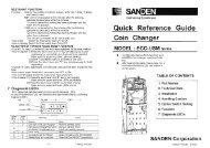
TCT-1<br />
P/N: 1122181<br />
REV B: 5/2002
V-MAX TRADE TABLE OF CONTENTS<br />
SAFETY SECTION.................................................................................... Pages S-1 - S-18<br />
A COMMITMENT TO SAFETY .................................................................. Page S-2<br />
VENDOR INSTALLATION......................................................................... Pages S-3 - S-6<br />
ELECTRICAL HAZARDS .......................................................................... Pages S-7 - S-8<br />
MECHANICAL HAZARDS ......................................................................... Page S-9<br />
REFRIGERATION HAZARDS ................................................................... Page S-10<br />
SUBSTITUTIONS AND MODIFICATIONS................................................. Pages S-11 - S-12<br />
CONSUMER SAFETY WARNING............................................................. Page S-13<br />
GAS ISLAND VENDOR INSTALLATION PROTOCOL.............................. Page S-14<br />
MOUNTING TO PEDESTAL...................................................................... Page S-15<br />
PARTS, SALES, AND SERVICE CENTERS OF VENDO/SANDEN CO. .. Pages S-16 - S-17<br />
GENERAL INFORMATION........................................................................ Pages G1 - G12<br />
GENERAL INFORMATION........................................................................ Page G-2<br />
INITIAL SET-UP ....................................................................................... Pages G-3 - G-4<br />
LABEL INSTALLATION............................................................................. Page G-5<br />
ALIGNMENT CHECKS.............................................................................. Page G-6<br />
LOADING INSTRUCTIONS....................................................................... Page G-7<br />
VEND MECHANISM PARTS DESCRIPTION............................................ Pages G-8 - G-9<br />
VEND CYCLE............................................................................................ Pages G-10 - G-11<br />
PROGRAMMING SECTION ...................................................................... Pages PC-1 - PC-22<br />
9.1 PROGRAMMING................................................................................. Pages PC-2 - PC-4<br />
SET-UP AND CODE DESCRIPTION ........................................................ Pages PC-5 - PC-18<br />
9.1 WIRING DIAGRAMS ........................................................................... Pages PC-19 - PC-22<br />
TRADE CABINET SECTION..................................................................... Pages C-1 - C-18<br />
READING A PARTS LIST ......................................................................... Page C-2<br />
HARDWARE LIST..................................................................................... Pages C-3 - C-4<br />
INNER DOOR ASSEMBLY........................................................................ Pages C-6 – C-7<br />
CABINET ASSEMBLY............................................................................... Pages C-8 - C-9<br />
STACK ASSEMBLY .................................................................................. Pages C-10 - C-13<br />
REFRIGERATION ASSEMBLY ................................................................. Pages C-14 - C-15<br />
AIR DAM ASSEMBLY ............................................................................... Pages C-16 - C-17<br />
TRADE DOOR SECTION.......................................................................... Pages TD-1 - TD-18<br />
OUTER DOOR .......................................................................................... Pages TD-2 - TD-13<br />
LOCK ASSEMBLY .................................................................................... Pages TD-14 - TD-15<br />
SELECTION PANEL ................................................................................. Pages TD-16 - TD-17<br />
MINI V-MAX DOOR SECTION................................................................... Pages TDS-1 - TDS-10<br />
OUTER DOOR .......................................................................................... Pages TDS-2 - TDS-5<br />
SELECTION PANEL ................................................................................. Pages TDS-6 - TDS-7<br />
LOCK ASSEMBLY .................................................................................... Pages TDS-8 - TDS-9<br />
TCT-2
GAS ISLAND VENDOR PARTS................................................................ Pages GIV-1 - GIV-16<br />
OUTER DOOR .......................................................................................... Pages GIV-2 - GIV-5<br />
LOCK ASSEMBLY .................................................................................... Pages GIV-6 - GIV-7<br />
COIN INSERT ........................................................................................... Pages GIV-8 - GIV-9<br />
SELECTION PANEL ................................................................................. Pages GIV-10 - GIV-11<br />
MOUNTING PEDESTAL ASSEMBLY ....................................................... Pages GIV-12 - GIV-13<br />
SWITCH MOUNT ASSEMBLY .................................................................. Pages GIV-14 - GIV-15<br />
MAINTENANCE......................................................................................... Pages M-1 - M-10<br />
PREVENTATIVE MAINTENANCE SUGGESTIONS.................................. Page M-2<br />
LUBRICATION GUIDE .............................................................................. Page M-2<br />
CARE AND CLEANING............................................................................. Page M-3<br />
REFRIGERATION OPERATION ............................................................... Pages M-4 – M-6<br />
REFRIGERATION PARTS DESCRIPTION ............................................... Pages M-7 - M-9<br />
TROUBLESHOOTING .............................................................................. Pages T-1 - T-8<br />
VENDO WARRANTY ................................................................................ Pages T-2 - T-3<br />
PARTS RETURN PROCEDURE............................................................... Page T-4<br />
TROUBLESHOOTING GUIDE .................................................................. Pages T-5 - T-8<br />
TCT-3
SAFETY SECTION<br />
S-1<br />
3/2002
A COMMITMENT TO SAFETY<br />
The <strong>Vendo</strong> Company is committed to safety in every aspect of our product design. <strong>Vendo</strong><br />
is committed to alerting every user to the possible dangers involved in improper handling<br />
or maintenance of our equipment. The servicing of any electrical or mechanical device<br />
involves potential hazards, both to those servicing the equipment and to users of the<br />
equipment. These hazards can arise because of improper maintenance techniques. The<br />
purpose of this manual is to alert everyone servicing <strong>Vendo</strong> equipment of potentially<br />
hazardous areas, and to provide basic safety guidelines for proper maintenance.<br />
This manual contains various warnings that should be carefully read to minimize the risk<br />
of personal injury to service personnel. This manual also contains service information to<br />
insure that proper methods are followed to avoid damaging the vendor or making it unsafe.<br />
It is also important to understand these warnings are not exhaustive. <strong>Vendo</strong> could not<br />
possibly know, evaluate, or advise of all of the conceivable ways in which service might be<br />
done. Nor can <strong>Vendo</strong> predict all of the possible hazardous results. The safety<br />
precautions outlined in this manual provide the basis for an effective safety program. Use<br />
these precautions, along with the service manual, when installing or servicing the vendor.<br />
We strongly recommend a similar commitment to safety by every servicing organization.<br />
Only properly-trained personnel should have access to the interior of the machine.<br />
This will minimize the potential hazards that are inherent in electrical and mechanical<br />
devices. <strong>Vendo</strong> has no control over the machine once it leaves the premises. It is the<br />
owner or lessor’s responsibility to maintain the vendor in a safe condition. See Section I of<br />
this manual for proper installation procedures and refer to the appropriate service manual<br />
for recommended maintenance procedures. If you have any questions, please contact the<br />
Technical Services Department of the <strong>Vendo</strong> office nearest you.<br />
SAFETY RULES<br />
• Read the Safety <strong>Manual</strong> before installation or service.<br />
• Test for proper grounding before installing to reduce the risk of electrical shock and<br />
fire.<br />
• Turn off power switch or disconnect power cord from wall outlet before servicing or<br />
clearing product jams. The vending mechanism can trap and pinch hands.<br />
• Use only fully-trained service technicians for Power- On servicing.<br />
• Remove any product prior to moving a vendor.<br />
• Use adequate equipment when moving a vendor.<br />
• Always wear eye protection, and protect your hands, face, and body when working<br />
near the refrigeration system.<br />
• Use only authorized replacement parts.<br />
• Be aware of inherent dangers in rocking or tipping a vending machine.<br />
• Always turn power off before plugging or unplugging vendor to wall outlet.<br />
S-2<br />
3/2002
SECTION I: VENDOR INSTALLATION<br />
A. <strong>Vendo</strong>rs are large, bulky machines of significant size and weight. Improper<br />
handling can result in injury. When moving a vendor, carefully plan the route to be<br />
taken and the people and equipment required to accomplish the task safely.<br />
B. Remove all tape, shipping sealant, and Styrofoam from the vendor. Loosen any<br />
shipping devices used to secure interior parts during shipping. Remove the wooden<br />
shipping base attached to the vendor base by the vendor leveling screws. Make<br />
certain the leveling screws are in place and functional.<br />
C. Position the vendor three to four inches (7.6 cm to 10.2 cm) from a well-constructed<br />
wall (of a building or otherwise) on a flat, smooth surface.<br />
IMPORTANT: The vendor requires three inches (7.6 cm) of air space from the wall<br />
to ensure proper air circulation to cool the refrigeration unit.<br />
D. Adjust the leveling screws to compensate for any irregularities on the floor surface.<br />
Ideally, no adjustment will be necessary and the leveling legs will be flush with the<br />
bottom of the vendor. A spirit level is a useful aid to level the vendor. When the<br />
vendor is properly leveled the outer door, when opened, will remain stationary.<br />
<strong>Vendo</strong>rs must be level to ensure proper operation and to maintain stability<br />
characteristics. Do not add legs to the vendor.<br />
E. Check the manufacturer’s nameplate on the left or right side of the vendor’s outer<br />
door to verify the main power supply requirements of the vendor. Be sure the main<br />
power supply matches the requirements of the vendor. To ensure safe operation,<br />
plug the vendor only into a properly grounded outlet.<br />
DO NOT USE EXTENSION CORDS.<br />
F. Recommended voltage specs = volts required + amps of circuit.<br />
G. Dedicated 15A service required for 1 machine.<br />
NOTE: Any power supply variance more than + 10% may cause the vendor to<br />
malfunction.<br />
* Power outlets must be properly grounded.<br />
* Power outlets must be properly polarized, where applicable.<br />
Test the outlets using the following information.<br />
(Refer to Figure 1 on Page S-4.)<br />
S-3<br />
3/2002
TYPE 1<br />
LARGE SLOT-LINE 2<br />
NEUTRAL CONTACT (WHITE) 0 - 5 VOLTS<br />
TYPE 2<br />
SLOT<br />
NEUTRAL CONTACT<br />
(BLUE) 0-5 VOLTS<br />
TYPE 3<br />
EARTH CONTACT<br />
(GREEN AND YELLOW)<br />
0 VOLTS<br />
TYPE 4<br />
EARTH CONTACT<br />
(GREEN AND YELLOW)<br />
0 VOLTS<br />
TYPE 5<br />
POWER CONTACT SOCKET<br />
NEUTRAL (BLUE) 0-5 VOLTS<br />
OR LIVE (BROWN) 220 VOLTS<br />
FIGURE 1<br />
SMALL SLOT-LINE 1<br />
LIVE CONTACT (BLACK)<br />
110 VOLTS<br />
ROUND SOCKET<br />
EARTH CONTACT<br />
(GREEN) 0 VOLTS<br />
EARTH CONTACT SLOT<br />
(GREEN AND YELLOW)<br />
0 VOLTS<br />
SLOT<br />
LIVE CONTACT<br />
(BROWN) 220 VOLTS<br />
POWER CONTACT SOCKET<br />
NEUTRAL (BLUE) 0-5 VOLTS<br />
OR LIVE (BROWN) 220 VOLTS<br />
POWER CONTACT<br />
SOCKET<br />
NEUTRAL (BLUE) 0-5 VOLTS<br />
OR LIVE (BROWN) 220<br />
POWER CONTACT SOCKET<br />
NEUTRAL (BLUE) 0-5 VOLTS<br />
OR LIVE (BROWN) 220 VOLTS<br />
POWER CONTACT<br />
SOCKET<br />
NEUTRAL (BLUE) 0-5 VOLTS<br />
OR LIVE (BROWN) 220 VOLTS<br />
POWER CONTACT SOCKET<br />
NEUTRAL (BLUE) 0-5 VOLTS<br />
OR LIVE (BROWN) 220 VOLTS<br />
STEP 1<br />
EARTH CONTACT SOCKET<br />
(GREEN AND YELLOW)<br />
0 VOLTS<br />
STEP 1<br />
STEP 1<br />
STEP 1 STEP 2<br />
STEP 1<br />
STEP 2<br />
STEP 2 STEP 3<br />
STEP 2<br />
STEP 2<br />
STEP 3<br />
STEP 3<br />
STEP 3<br />
STEP 3<br />
CHECKING FOR PROPER GROUNDING AND POLARIZATION<br />
S-4<br />
3/2002
SECTION I: VENDOR INSTALLATION (CONTINUED)<br />
For Type 1 and Type 2 outlets, test for Grounding and Polarization as follows:<br />
1. With a test device (volt meter or test light), connect one probe to the receptacle’s<br />
neutral contact and the other to the live contact. The test device should show a<br />
reaction.<br />
2. Connect one probe to the receptacle’s earth contact and the other to the live<br />
contact. The test device should show a reaction.<br />
For Type 3 through Type 5 outlets, test for Grounding as follows:<br />
1. With a test device (volt meter or test light), determine which of the receptacle’s<br />
power contacts is the live contact.<br />
A. Connect one probe to the receptacle’s earth contact.<br />
B. Connect the second probe to the left (or upper) power contact. If a reaction<br />
occurs, this is the live power contact. If a reaction does not occur, move the<br />
second probe to the right (or lower) contact. A reaction should occur,<br />
indicating that this is the live power contact.<br />
2. Connect one probe to the receptacle’s live power contact (as determined in step 1).<br />
Connect the second probe to the other power contact (neutral). The test device<br />
should show a reaction.<br />
IF THE ABOVE CONDITIONS ARE NOT MET FOR THE GIVEN OUTLET<br />
TYPE, CONTACT A LICENSED ELECTRICIAN AND HAVE THE<br />
NECESSARY CORRECTIONS MADE.<br />
S-5<br />
3/2002
SECTION I: VENDOR INSTALLATION (CONTINUED)<br />
H. Door Support (Figure 2)<br />
The door support is to ensure that the<br />
outer door closes squarely to the cabinet.<br />
Raising the door can also ensure proper<br />
alignment of the door latch.<br />
I. Door Latch Alignment (Figure 3)<br />
After any door adjustment, the floating quicker<br />
lock assembly should align itself automatically.<br />
The latch assembly is adjustable. To adjust,<br />
loosen the latch bracket mounting screws,<br />
raise or lower the latch assembly into position,<br />
then tighten the mounting screws.<br />
LATCH<br />
BRACKET<br />
FIGURE 3<br />
MOUNTING<br />
SCREW<br />
S-6<br />
FIGURE 2<br />
DO NOT INSERT OBJECTS<br />
INTO LOCK CAVITY.<br />
2<br />
1<br />
TO FREE OBJECTS, REMOVE<br />
LOCK CAP AS SHOWN<br />
WARNING:<br />
KEEP FINGERS AND OTHER OBJECTS OUT OF LOCK CAVITY<br />
NOTE: Refer to the appropriate parts and service manual for detailed<br />
instructions, operating principles, and recommended maintenance<br />
intervals and procedures.<br />
3/2002
SECTION II: ELECTRICAL HAZARDS<br />
GENERAL<br />
<strong>Vendo</strong> vending machines are provided with the appropriate power supply setting for your<br />
area. Some models are equipped with step-down transformers, as required. This enables<br />
the vending machine to operate on different main voltages. Refer to Section I. E. for<br />
information to determine the main power requirements. Refer to the appropriate service<br />
manual for details of step-down transformer operations.<br />
The power sources just mentioned are standard for both household and commercial<br />
lighting and appliances. However, careless or improper handling of electrical circuits can<br />
result in injury or death. Anyone installing, repairing, loading, opening, or otherwise<br />
servicing a vending machine should be alerted to this point. Apply all of the normal<br />
precautions observed in handling electrical circuits, such as:<br />
• Refrigeration servicing to be performed by qualified personnel only.<br />
• Unplug the vendor or move power switch to off position before servicing or clearing<br />
product jams.<br />
• Replace electrical cords if there is any evidence of fraying or other damage.<br />
• Keep all protective covers and ground wires in place.<br />
• Plug equipment into outlets that are properly grounded and polarized (where<br />
applicable), and protected with fuses or circuit breakers.<br />
• All electrical connections must be dry and free of moisture before applying power.<br />
A. Grounding Systems<br />
<strong>Vendo</strong> vending machines are provided with the appropriate service cord for the<br />
power supply in your area. The service cord will connect to the matching electrical<br />
outlet. Always ensure that the outlet to be used is properly grounded before<br />
plugging in the vendor. (See pages S-3 through S-5.)<br />
WARNING:<br />
ALWAYS TEST TO VERIFY PROPER GROUNDING PRIOR TO<br />
INSTALLATION TO REDUCE THE RISK OF ELECTRICAL<br />
SHOCK AND FIRE<br />
The electrical grounding system also includes the bonding of all metal components within<br />
the vendor. This involves a system of bonding wires identified by green or green and<br />
yellow marking. The system uses serrated head screws, lock washers, and star washers<br />
to ensure the electrical connection between parts. Maintenance of vending equipment<br />
may involve disassembly. Include the above items when reassembling, even if the<br />
vending machine may appear to function normally without them. Omitting any of these<br />
items can compromise a link in the grounding system. See the appropriate service<br />
manual or kit instructions for components and assembly instructions.<br />
S-7<br />
3/2002
SECTION II: ELECTRICAL HAZARDS (CONTINUED)<br />
B. Servicing with “Power Off”<br />
For maximum safety, unplug the service cord from the wall outlet before opening<br />
the vendor door. This will remove power from the equipment and avoid electrical<br />
and mechanical hazards. Service personnel should remain aware of possible<br />
hazards from hot components even though electrical power is off. See the<br />
appropriate sections of this manual for further information.<br />
C. Servicing with “Power On”<br />
Some service situations may require access with the power on. Power on servicing<br />
should be performed only by fully-qualified service technicians. Particular<br />
caution is required in servicing assemblies that combine electrical power and<br />
mechanical movement. Sudden movement (to escape mechanical action) can<br />
result in contact with live circuits and vice versa. It is therefore doubly important to<br />
maintain maximum clearances from both moving parts and live circuits when<br />
servicing.<br />
WARNING:<br />
“POWER-ON” SERVICING SHOULD BE ACCOMPLISHED ONLY BY<br />
FULLY-TRAINED PERSONNEL. SUCH SERVICE BY UNQUALIFIED<br />
INDIVIDUALS CAN BE DANGEROUS.<br />
Power to lighting and refrigeration system is shut off automatically by the electronic<br />
controller when the outer door is opened. Applies to V-<strong>Max</strong> only.<br />
NOTE: For power-on servicing of the vendor’s lighting system, turn lighting power on by<br />
accessing the “LIT” test function of the electronic controller (see programming<br />
on inner door). Applies to V-<strong>Max</strong> only.<br />
For power-on servicing of the vendor’s refrigeration system, turn refrigeration<br />
power on by accessing the “CNPR” test function of the electronic controller (see<br />
programming on inner door). Applies to V-<strong>Max</strong> only.<br />
SECTION III: MECHANICAL HAZARDS<br />
S-8<br />
3/2002
A. Servicing of Moving Parts and Assemblies<br />
When servicing assemblies involving moving parts, use extreme caution!! Keep<br />
fingers, hands, loose clothing, hair, tools, or any foreign material clear of<br />
entrapment.<br />
As noted before under the electrical hazards section, Power On servicing should<br />
only be performed by qualified personnel. Refer to and heed the warnings noted in<br />
the electrical hazards section. These warnings refer to the potential hazards<br />
associated with electrical power and moving parts. Always maintain maximum<br />
clearances from electrical and moving parts.<br />
Always install protective covers and guards when reassembling equipment.<br />
WARNING:<br />
THIS VENDING MACHINE INCLUDES MECHANICAL EQUIPMENT<br />
WHICH CAN BE HAZARDOUS IF IMPROPERLY HANDLED OR<br />
SERVICED. USE CAUTION AND CONSULT THE VENDO SAFETY<br />
MANUAL AND THE VENDO SERVICE MANUAL FOR ADDITIONAL<br />
SAFETY INFORMATION.<br />
WARNING<br />
RISK OF ENTRAPMENT !<br />
S-9<br />
WARNING<br />
RISK OF SHOCK !<br />
ELECTRICAL !<br />
3/2002
GENERAL<br />
SECTION IV: REFRIGERATION HAZARDS<br />
Refrigeration systems involve both electrical power and mechanical action. These<br />
systems may present any of the potential dangers shown in the sections on electrical and<br />
mechanical hazards contained in this manual. See Sections II and III for further<br />
information.<br />
A. Compressed Refrigerant<br />
Refrigeration systems involve the compression and evaporation of gases. The<br />
pressures contained represent a potential hazard if suddenly released in confined<br />
areas. Caution is required when performing maintenance tests or repairs. All<br />
testing of sealed refrigeration systems must be done by trained personnel who are<br />
familiar with the systems and pressures involved.<br />
B. Physical Protection<br />
The accidental release of refrigerant gases can result in physical injuries. Always<br />
wear protective glasses and protect your hands, face, and body when working near<br />
the refrigeration system.<br />
GENERAL<br />
WARNING:<br />
ALWAYS WEAR EYE PROTECTION AND PROTECT YOUR HANDS,<br />
FACE, AND BODY WHEN WORKING NEAR THE REFRIGERATION<br />
SYSTEM.<br />
SECTION V: TEMPERATURE HAZARDS<br />
Maintenance personnel should be alerted to the potential hazards from hot metal surfaces.<br />
High temperatures may be present throughout the refrigeration system even though<br />
electrical power has been removed.<br />
S-10<br />
3/2002
GENERAL<br />
SECTION VI: SUBSTITUTIONS AND MODIFICATIONS<br />
Unauthorized changes or the substitution of unauthorized parts can compromise the<br />
equipment designs. This can result in unsafe conditions for either the service<br />
personnel or the equipment users. Always refer to the appropriate parts and service<br />
manual for replacement parts and maintenance instructions. If questions arise,<br />
contact the Technical Services Department of the <strong>Vendo</strong> office in your area.<br />
When servicing the vending machine, always reassemble all components to their<br />
original location and position. Maintain the correct routing for tubing, electrical wiring,<br />
etc. Replace all clamps, brackets, and guides to their original locations. Replace all<br />
tubing, sleeving, insulating material, and protective covers to their original condition.<br />
WARNING:<br />
VENDO EQUIPMENT HAS BEEN PROVIDED WITH APPROPRIATE<br />
PROTECTIVE DEVICES TO PROTECT AGAINST THE POSSIBILITY<br />
OF OVERHEATING AND FIRE AS A RESULT OF EQUIPMENT OR<br />
COMPONENT FAILURES. SUBSTITUTION, MODIFICATION, OR<br />
BYPASSING OF SUCH PROTECTIVE DEVICES CAN CREATE<br />
DANGEROUS CONDITIONS. PROTECTIVE CIRCUITS SHOULD<br />
NEVER BE BYPASSED, AND FAILED PROTECTIVE DEVICES MUST<br />
BE REPLACED ONLY WITH FACTORY-AUTHORIZED PARTS.<br />
A. Service Cord Replacement<br />
<strong>Vendo</strong> vending machines are furnished with unique power supply cords. If<br />
replacement becomes necessary, consult the appropriate parts and service manual<br />
and order the correct replacement cord for the model of vending machine in<br />
question. Do not use substitute replacement cords. Only authorized service<br />
personnel with appropriate training should replace the vending machine service<br />
cord. If a question should arise concerning which service cord to order, contact the<br />
Technical Services Department of the <strong>Vendo</strong> office in your area.<br />
S-11<br />
3/2002
SECTION VI: SUBSTITUTIONS AND MODIFICATIONS (CONTINUED)<br />
WARNING:<br />
THIS APPLIANCE MUST BE EARTHED.<br />
IMPORTANT!<br />
The wires in the main leads are colored in accordance with the following code:<br />
110v/120v 220v/240v<br />
Green Green and Yellow ............................ Earth<br />
White Blue................................................... Neutral<br />
Black Brown ............................................... Live<br />
S-12<br />
3/2002
SECTION VII: CONSUMER SAFETY WARNING<br />
WARNING:<br />
VENDOR CAN BE OVERTURNED IF SUFFICIENT FORCE IS<br />
APPLIED, AND MAY RESULT IN SERIOUS INJURY OR DEATH.<br />
GENERAL<br />
There have been incidents, including fatalities, when vending machines have been<br />
vandalized by being pulled over in an attempt to obtain free product or money.<br />
To warn of the danger involved in tipping, shaking, or rocking the vending machine, a<br />
decal has been designed to be affixed to vending machines. (One such decal is<br />
supplied with the vending machine.) <strong>Vendo</strong> will supply sufficient decals to be placed<br />
on all machines, on request. If you have any questions, contact the Technical Services<br />
Department of the <strong>Vendo</strong> office in your area.<br />
THE FOLLOWING DECAL SHOULD BE PLACED IN A POSITION ON<br />
THE VENDOR CONTROL PANEL AT EYE LEVEL.<br />
WARNING<br />
Never rock or tilt.<br />
Machine can fall over<br />
and cause serious<br />
injury or death.<br />
Vending machine will<br />
not dispense free<br />
product.<br />
ENGLISH<br />
389611A<br />
S-13<br />
MISE EN<br />
GARDE<br />
Ne jamais secouer<br />
ou incliner.<br />
Le distributeur peut<br />
se renverser et causer<br />
des blessures graves<br />
ou la morte.<br />
Cette machine ne<br />
distribue pas de<br />
produits gratuitement.<br />
FRENCH<br />
389611-1A<br />
AVISO<br />
Nunca voltie o incline<br />
esta maquina.<br />
Puede caer sobre usted<br />
y cauzarle heridas<br />
graves o matarle.<br />
Esta <strong>Vendo</strong>matica no<br />
provee producto gratis.<br />
SPANISH<br />
389611-2A<br />
3/2002
GAS ISLAND VENDOR INSTALLATION PROTOCOL<br />
<strong>Vendo</strong> Gas Island Vending Machines have been evaluated by UL (Underwriters<br />
Laboratories Inc.®) for placement at service stations which the NFPA (National Fire<br />
Protection Association) considers a hazardous location. These vendors must be<br />
correctly installed and inspected per the following protocol before they are put into<br />
service.<br />
A. <strong>Vendo</strong>r is to be installed in accordance with the National Electrical Code, NFPA 70,<br />
Article 514 - Gasoline Dispensing and Service Stations, NFPA 30A - Automotive and<br />
Marine Service Station Code, and the Local Authority Having Jurisdiction.<br />
IMPORTANT - Compliance includes direct wiring of the vendor to the voltage source<br />
utilizing proper metal conduit and circuit protection.<br />
B. When installed on support base, the vendor can be installed in an 18-inch high Class<br />
I, Group D, Division 2 Hazardous Location. Additionally, the vendor must be installed<br />
at least 18 inches from any flammable liquid dispensing device.<br />
<strong>Vendo</strong>r support base is to be attached to vendor as shown by view on page S-15.<br />
<strong>Vendo</strong>r should be securely bolted in place using ½-inch nominal diameter hardware<br />
as a minimum.<br />
C. IMPORTANT: FOR ANY INSTALLATION REQUIRING LEVELING OF THE<br />
VENDOR, IT IS MANDATORY TO OBTAIN APPROVAL OF THE LOCAL<br />
AUTHORITY HAVING JURISDICTION. THERE ARE NO EXCEPTIONS.<br />
To level more than 1/8 inch, it is suggested to follow these guidelines:<br />
1. Shimming of one or more mounting points should be done with solid steel,<br />
minimum thickness of 1/8 inch. Solid aluminum is acceptable.<br />
2. It is not acceptable to place shims under all (4) mounting points.<br />
3. Shims should be a minimum of 2 ½ inch x 2 ½ inch square or 2 ½ inch diameter.<br />
4. Shim should have a hole, (approximately ½ inch diameter), through the center in<br />
the same manner as the GIV pedestal foot.<br />
5. Shim should be protected against corrosion by painting, plating, etc.<br />
6. IMPORTANT: Hold down bolt should be a solid, continuous bolt.<br />
It is MANDATORY that all installations requiring leveling be approved by the<br />
LOCAL AUTHORITY HAVING JURISDICTION.<br />
D. Warning - Power tools with arcing and sparking parts, such as electric drills, should<br />
not be used in any hazardous locations during the installation of this vendor.<br />
E. The dispensing area shall be in clear view of the attendant at all times, and placing or<br />
allowing any obstacle to come between the dispensing area and the attendant control<br />
area shall be prohibited.<br />
F. Upon completion of the installation, the Local Fire Marshall, or Authority Having<br />
Jurisdiction, must verify the installation complies with the codes shown in Item A.<br />
After authorization, the vendor may be placed into operation.<br />
S-14<br />
3/2002
MOUNTING TO PEDESTAL<br />
PEDESTAL<br />
FRONT AND REAR COVER<br />
VENDOR<br />
FLAT WASHER<br />
LOCK WASHER<br />
HEX BOLT 1/2"-13x1 1/2"<br />
IMPORTANT - INSTALLATION REQUIREMENTS<br />
Electrical equipment, such as vending machines, installed within a 20-ft. radius of a<br />
gasoline dispensing unit must meet safety specifications of the National Electrical<br />
Code, NFPA 70 - Article 514 - Gasoline Dispensing and Service Stations, NFPA 30A -<br />
Automobile and Marine Service Station Code, and the Local Authority Having<br />
Jurisdiction. Safety Specifications are:<br />
• The vending machine must be UL Listed for installation near gasoline dispensing<br />
equipment.<br />
• The vending machine is UL Listed for use in an 18-inch high Class I, Group D,<br />
Division 2 Hazardous Location.<br />
• Installation requires ON-SITE approval of Local Fire Marshall, or Authority Having<br />
Jurisdiction.<br />
• The vending machine should be securely bolted in place using ½” nominal diameter<br />
hardware as a minimum. Use template provided on pedestal carton for mounting<br />
locations. If vendor requires leveling more than 1/8 inch, refer to Page S-14.<br />
• The vending machine must be direct-wired to the voltage source utilizing proper<br />
metal conduit and circuit protection.<br />
Note: There are unique safety and approval considerations required for placement of a<br />
vendor at the gasoline island which will require a non-standard vending machine. A<br />
standard vending machine located at or near the gasoline dispensing area will create<br />
unacceptable risks and will not meet safety agency requirements.<br />
S-15<br />
3/2002
PARTS, SALES, & SERVICE CENTERS OF VENDO/SANDEN COMPANY<br />
AREA ADDRESS PHONE NUMBERS<br />
United States, The <strong>Vendo</strong> Company<br />
Tel: (559) 439-1770<br />
Canada<br />
7209 N. Ingram<br />
Fresno, CA 93650 U.S.A.<br />
Fax: (559) 439-2083<br />
Japan Sanden International Corporation<br />
Tel: (81) 3-3835-1321<br />
31-7 Taito 1-Chome<br />
Taito-ku<br />
Tokyo 110, Japan<br />
Fax: (81) 3-3833-7096<br />
Europe, Mid-East, <strong>Vendo</strong> GMBH<br />
Tel: (49) 211-74-039-0<br />
Africa, Mid-Asia Spangerstr. 22, P.O. Box 130940<br />
40599 Dusseldorf<br />
Germany<br />
Fax: (49) 211-7488541<br />
Australia,<br />
Sanden International Pty. Ltd.<br />
Tel: 61-2-9791-0999<br />
New Zealand 54 Allingham St., Condell Park<br />
N.S.W. 2200<br />
Australia<br />
Fax: 61-2-9791-9029<br />
Singapore,<br />
Sanden International (Singapore) Pte., Ltd. Tel: 65-482-5500<br />
Hong Kong, Sanden House, 25, Ang Mo Kio St. 65<br />
Fax: 65-482-1697<br />
Indonesia,<br />
Singapore 569062<br />
Philippines, India The Republic of Singapore<br />
Taiwan Sanden International Taiwan Corp.<br />
Tel: 886-2-570-6106<br />
No, 21-6, Sec 1<br />
Tun Hwa S. Rd., Taipei, Taiwan<br />
Taiwan, ROC<br />
Fax: 886-2-577-1959<br />
Belgium N.V. <strong>Vendo</strong> Benelux, S.A.<br />
Tel: 32-2-268-2595<br />
Industrial Research Park N.O.H.<br />
13 Font St. Landry<br />
1120 Brussels<br />
Belgium<br />
Fax: 32-2-268-2862<br />
England Vendhall, Ltd.<br />
Tel: 44-1256-479309<br />
Unit 17, The Basingstoke Enterprise Centre<br />
Westham Lane, Worting Rd,<br />
Basingstoke, Hants RG22, 6NQ<br />
Great Britain<br />
Fax: 44-1256-844469<br />
Italy <strong>Vendo</strong> Italy S.p.A.<br />
Tel: 39-142-335111<br />
Casella Postale 9<br />
1-15033 Casale Monferrato<br />
Italy<br />
Fax: 39-142-5623-48<br />
Spain <strong>Vendo</strong> Iberia, S.A.<br />
Tel: 343-474-1555<br />
C/ Sant Ferran No. 92<br />
Poligono Industrial la Almeda, Sector P-1<br />
08940 Cornella, (Barcelona), Spain<br />
Fax: 343-474-1842<br />
S-16<br />
3/2002
PARTS, SALES, & SERVICE CENTERS OF VENDO/SANDEN COMPANY<br />
FOR LATIN AMERICA<br />
AREA ADDRESS PHONE NUMBERS<br />
Mexico <strong>Vendo</strong> de Mexico<br />
Camino Real de Toluca No. 154<br />
Col. Bellavista<br />
01140 Mexico D.F. Mexico<br />
Central America The <strong>Vendo</strong> Company<br />
7209 N. Ingram<br />
Fresno, CA 93650 U.S.A.<br />
Chile Pelp Internacional, S.A.<br />
4560 El Rosal<br />
Huechuraba, Santiago, Chile<br />
Brazil Cimaq Industria e Comercio de Maq,<br />
Ltda.<br />
Estrada Uniao e Industria, 9.120 Itaipava<br />
25730-730 Petropolis<br />
Rio de Janeiro, Brazil<br />
South America The <strong>Vendo</strong> Company<br />
7209 N. Ingram Ave.<br />
Fresno, CA 93650 U.S.A.<br />
S-17<br />
Tel: (525) 515-9745<br />
Fax: (525) 277-0111<br />
Tel: (559) 439-1770<br />
Fax: (559) 439-2083<br />
Tel: (562) 243-9710<br />
Fax: (562) 740-0504<br />
Tel: (55242) 22-2666<br />
Fax: (55242) 22-3244<br />
Tel: (559) 439-1770<br />
Fax: (559) 439-2083<br />
3/2002
NOTES<br />
S-18<br />
3/2002
GENERAL INFORMATION<br />
G-1<br />
3/2002
GENERAL INFORMATION<br />
This manual contains programming, operation, and complete parts and electrical wiring<br />
diagrams.<br />
The V-<strong>Max</strong> controller is a microprocessor which will permit pricing per selection from<br />
0.00 to 99.99. This machine also has space-to-sales programming as well as energy<br />
savings modes.<br />
Specifications:<br />
MODEL V-MAX 720 V-MAX 840 V-MAX 576<br />
SELECTIONS 10 10 8<br />
DIMENSIONS (HEIGHT X WIDTH X DEPTH)<br />
CURVED DOOR 72” x 39 ½ “ x 35” 79” x 39 ½ “ x 35” 72” x 32 ½ “ x 34 ¾”<br />
FLAT DOOR 72” x 39 ½” x 32 ½” 79” x 39 ½” x 32 ½” Not Available<br />
SINGLE COLUMNS 10 10 8<br />
CAPACITY<br />
PER<br />
COLUMN<br />
12 oz. CAN***<br />
16 oz. GLASS<br />
20 oz. **<br />
72<br />
30<br />
32<br />
SHIPPING WEIGHT 685 Ibs 750 Ibs 640 Ibs<br />
OPERATION VOLTAGE 115v 60 Hz. 115v 60Hz. 115v 60Hz.<br />
AMP. RATING 10 10 10<br />
REFRIGERATION<br />
VOLTAGE<br />
115v 60Hz. 115v 60Hz. 115v 60Hz.<br />
*Dimensions and shipping weight will vary slightly due to manufacturing tolerances,<br />
shipping boards and whether or not coinage is installed.<br />
** 20 oz. PET capacity may vary based on the shape and size of the bottle.<br />
***12 oz. can capacities are listed using a 4-deep set up.<br />
G-2<br />
84<br />
36<br />
38<br />
3/2002<br />
72<br />
30<br />
32
INITIAL SET-UP<br />
A. UNPACKING<br />
Remove all plastic film, cardboard and tape from the outside of the vendor. Loosen<br />
any shipping devices used to secure interior parts during shipment (backspacer,<br />
shims or spacers).<br />
To remove shipping boards from base, raise vendor on a well-stabilized lifting<br />
device. Remove the leveling bolts which hold the boards in place and remove the<br />
boards. Replace bolts to equal heights in the threaded holes.<br />
Another method to remove shipping boards is to split the boards apart. Using a<br />
pinch bar or a heavy screwdriver and hammer, insert tool into the slots and force the<br />
boards apart.<br />
B. POSITIONING<br />
IMPORTANT: PLACE THE VENDOR IN DESIRED LOCATION AT LEAST THREE<br />
TO FOUR INCHES (7.6CM TO 10.2CM) AWAY FROM ANY REAR<br />
OBSTRUCTION. This is for proper air flow through the refrigeration compartment.<br />
The refrigeration system requires front to rear air circulation for proper operation.<br />
C. POWER SUPPLY CONNECTION<br />
CAUTION: DO NOT USE AN EXTENSION CORD!<br />
The vendor’s power requirements will vary depending upon the country it was<br />
purchased for. To verify the power requirements of the vendor, check the serial<br />
plate located on the hinged side of the outer door (see Figure 4 on page G-4). The<br />
power requirements are listed on the serial plate.<br />
To insure safe operation of the vendor, the vendor’s power supply must be a<br />
properly grounded and polarized outlet. Before plugging the vendor into the outlet,<br />
test the outlet to confirm it will meet the vendor’s power requirements. If the power<br />
supply of the outlet is different from the power requirements of the vendor, a<br />
transformer may be necessary.<br />
If the power requirements are not properly met, contact a licensed electrician and<br />
have the necessary correction made.<br />
Should you require additional information, contact the Technical Services<br />
Department of the <strong>Vendo</strong> office in your area.<br />
G-3<br />
3/2002
FIGURE 4<br />
NOTE: The Model number of the vending machine is located on the top, left hand<br />
corner of the serial plate. Do Not use the “BASIC UNIT” number. The<br />
BASIC UNIT number is the cabinet size, which is used on a number of different<br />
machines. A typical model number could read “540TDD00029”. The 540 is the<br />
model number, TDD represents the product line of the vendor, and the<br />
remaining digits tell what options are included.<br />
G-4<br />
3/2002
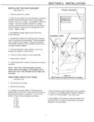
COIN INSERT<br />
A<br />
COIN INSTRUCTION LABEL<br />
FIGURE 5 FIGURE 6<br />
LABEL INSTALLATION<br />
COIN INSTRUCTION LABEL & PRICE LABEL APPLICATION:<br />
Apply labels to a clean and dry surface. Peel backing from label and apply with firm,<br />
even pressure.<br />
INSTRUCTION LABEL<br />
(Refer to Figure 5 for the following information.)<br />
Coin insert “A” has a separate validator opening, and insert “B” shows the validator<br />
opening built into the coin insert. Apply instruction label to area shown (as needed by<br />
the vendor).<br />
FLAVOR LABELS INSTALLATION:<br />
In Figures 6 & 7, corresponding styles are indicated by A, B, C, D, or E notations.<br />
Insert flavor labels to the side or top of selection window or button depending on the<br />
style. See Figure 6 for selection style. Rear views of windows and buttons are shown<br />
in Figure 7. Arrows point the direction to insert labels.<br />
Selection window and selection button labels identify product contained in columns.<br />
STYLE- A<br />
FIGURE 7<br />
PRICE DISPLAY<br />
COIN INSTRUCTION LABEL<br />
COIN INSERT<br />
B<br />
PRICE DISPLAY<br />
STYLE- B STYLE- C<br />
G-5<br />
STYLE A<br />
STYLE- D<br />
STYLE B<br />
STYLE- E<br />
3/2002<br />
STYLE C<br />
NOTE: The selection panel used with<br />
styles D and E is not depicted in Figure 6.
FIGURE 8<br />
FIGURE 9<br />
COMPRESSOR<br />
ALIGNMENT CHECKS<br />
DOOR ROLLER CHECK:<br />
The door support is to insure that the outer door closes squarely to the cabinet.<br />
Raising the door can also insure proper alignment of the door latch (see Figure 8).<br />
REFRIGERATION AREA CHECK:<br />
Check the position of the condensation pan (see Figure 9). The correct position of<br />
the pan is between the compressor and the condenser fan bracket. Be sure the<br />
drain tube is clipped to the pan and is free of kinks. A water trap is installed into the<br />
condensation pan and will prevent warm, moist air from reaching the evaporator<br />
area.<br />
G-6<br />
DRAIN TUBE<br />
CONDENSATION PAN<br />
CONDENSER FAN BRACKET<br />
3/2002
LOADING INSTRUCTIONS<br />
BASIC LOAD SET-UP:<br />
The V-<strong>Max</strong> machine is capable of vending a variety of products. For specific<br />
information, refer to the product set-up label on the machine inner door or contact<br />
the Technical Services Department of the <strong>Vendo</strong> office in your area.<br />
Load product evenly. Bottles are loaded with crown end placed toward the back of<br />
the column. In initial loading, prime the machine by advancing the product into the<br />
buckets. To advance product into buckets, use the vend test function of the<br />
electronic controller. When the bucket is loaded, the column is ready to vend.<br />
PRIME ALL COLUMNS DURING INITIAL PRODUCT LOADING<br />
G-7<br />
3/2002
VEND MECHANISM PARTS DESCRIPTION<br />
The parts listed below are part of the vend motor mechanism (refer to Figure 10 on<br />
page G-9). One mechanism is required per column. The parts are interchangeable.<br />
Setting will differ between single, double, triple, and quadruple depth.<br />
VEND MOTOR ASSEMBLY: P/N 1115821<br />
The motor is attached to the mech plate by three screws.<br />
TIMING CAM: P/N 1113236; RETAINER: P/N 1113244<br />
The motor cam assembly consists of two parts, the cam and the cam retainer. The cam<br />
controls the vend cycle. The cam is attached to the motor by the cam retainer. The<br />
retainer rotates left or right, and provides for single, double, triple, or quadruple depth<br />
operation.<br />
SOLD-OUT SWITCH: P/N 368299<br />
There is one sold-out switch above the vend motor. The sold-out switch is actuated by<br />
the sold-out flap when the column is empty. It prevents the motor from running when<br />
the columns are empty.<br />
VEND BUCKET: P/N 1120146<br />
The vend bucket holds the product(s) in a “ready to vend” position at the base of each<br />
column.<br />
MOTOR COUPLING: P/N 1076465<br />
The adapter coupling couples the motor to the bucket. It is located behind the motor, on<br />
the motor shaft.<br />
ANTI-THEFT CLIP: P/N 389712<br />
The anti-tilt clip prevents product from dropping out of the bucket if the vendor is tilted.<br />
The anti-theft clips are located in the bucket.<br />
GATE: P/N 1121282<br />
The gate holds product above the vend bucket.<br />
G-8<br />
3/2002
GATE LINK: P/N 1120140<br />
The rotation of the vend bucket moves the gate link. This opens the gate, allowing<br />
one layer of product to drop into the bucket.<br />
GAGE BAR: P/N 1111651<br />
The gage bar holds the product(s) inside the bucket. It also regulates which product<br />
is vended first when double, triple or quadruple depth settings are used. (See page<br />
G-10 for motor cam settings.)<br />
GAGE BAR CLIPS: P/N 1066104(white), 1066112(black), 1066112-1(gray),<br />
1121704(gray), 1122103(black)<br />
Gage bar clips are attached to the gage bar to create multiple steps when vending<br />
product double, triple, or quadruple depths. (See product set-up label on inner door<br />
for details.)<br />
FIGURE 10<br />
SOLD-OUT LEVER<br />
VEND MOTOR<br />
ASSEMBLY<br />
MOTOR CAM & RETAINER<br />
G-9<br />
GATE<br />
LINK<br />
COUPLER<br />
GATE<br />
BUCKET<br />
ANTI-TILT CLIP<br />
3/2002<br />
GAGE BAR<br />
GAGE BAR CLIPS
VEND CYCLE<br />
Several operations take place during the vend cycle: When a selection is made, the cam<br />
and bucket rotate, product is dispensed and the bucket is then reloaded. The sequence<br />
of these operations change slightly when the column’s depth setting is changed. With<br />
the single depth setting, one purchase is made and the bucket is reloaded. The cam<br />
sequence occurs one time per bucket revolution. With the double depth setting, two<br />
purchases are made before the bucket is reloaded, and the cam sequence occurs twice<br />
per bucket revolution. With the triple depth setting, three purchases are made and the<br />
cam sequences three times per bucket revolution. With the quadruple depth setting, four<br />
purchases are made and the cam sequences four times per bucket revolution.<br />
PURCHASE SEQUENCE: (See Figure 11, quadruple depth setting pictured)<br />
PS 1. Customer inserts money.<br />
PS 2. The coinage reports credit to the vending machine electronic controller.<br />
Established credit is displayed on the digital display located near the coin insert<br />
slot.<br />
PS 3. Customer presses a selection button.<br />
PS 4. The controller receives the signal from the selection switch and (if sufficient<br />
credit exists) energizes the corresponding vend motor.<br />
PS 5. The vend motor rotates the bucket and cam. As the cam rotates, the motor<br />
position switch actuator raises to the outer surface of the cam. This closes the<br />
switch which signals the controller to remove credit.<br />
PS 6. Product is immediately dispensed. The motor and cam continue to rotate until<br />
the motor position switch actuator drops into the low part of the cam.<br />
PS 7. Motor stops.<br />
ITEM 1<br />
IN STAND-BY<br />
POSITION<br />
4<br />
1<br />
3<br />
2<br />
ITEM 2<br />
IS PS-5 - PS-6<br />
3<br />
2<br />
4<br />
1<br />
FIGURE 11<br />
NOTE: The numbers on the cam reflect the number of vends allowed per cycle.<br />
G-10<br />
3<br />
2<br />
4<br />
1<br />
CAM<br />
CAM<br />
RETAINER<br />
3/2002
RELOADING SEQUENCE (See Figure 12)<br />
RS1. The gate link rests at a locked position in a cut out on the mech plate. This locked<br />
position prevents the gate from opening out of sequence.<br />
RS2. The gate link is guided by a slot in the mech plate and is actuated by a ridge on<br />
the bucket. As the bucket turns, the gate link is moved out of the locked position.<br />
RS3. As the gate link rises, the gate is opened. The spring maintains pressure on the<br />
gate link and the gate.<br />
RS4. Product falls into the bucket, the gate link returns to the locked position and the<br />
gate is closed.<br />
RS5. The bucket releases the gate link causing the gate to rest against the product.<br />
RS6. As the product falls into the bucket, the gate link returns to the locked position and<br />
the gate is closed.<br />
RS7. The product remaining in the column is held by the closed gate, keeping it above<br />
the bucket.<br />
RS8. The bucket stops, loaded with product and is ready to vend.<br />
FIGURE 12<br />
GATE<br />
ITEM 1<br />
RS-1<br />
RS-8<br />
ITEM 3<br />
GATE<br />
LINK<br />
BUCKET<br />
SPRING<br />
ITEM 2<br />
ITEM 4<br />
RS-2 RS-3<br />
SPRING<br />
GATE<br />
LINK<br />
ITEM 5<br />
RS-4<br />
RS-5<br />
G-11<br />
GATE<br />
ITEM 6<br />
RS-6<br />
BUCKET<br />
ITEM 7<br />
RS-7<br />
3/2002
NOTES<br />
G-12<br />
3/2002
9.1 PROGRAMMING SECTION<br />
PC-1<br />
3/2002
All programming of the V-<strong>Max</strong> is done in the service mode as indicated in the following steps<br />
below. The main service modes are indicated in white text and the sub-modes are indicated<br />
in black text.<br />
Example:<br />
tIne<br />
YeAr<br />
nth<br />
dATe<br />
Hour<br />
Dst<br />
Time/Date Setting Mode<br />
Year Setting<br />
Month Setting<br />
Date Setting<br />
Hour Setting<br />
Daylight Saving Time<br />
PC-2<br />
3/2002
THREE-BUTTON PROGRAMMING<br />
All programming of the V-<strong>Max</strong> options is done in the service mode. To enter the service<br />
mode open the vendor door, find the service mode button located on the control board, then<br />
press and release the service mode button which is located on the controller board. (See<br />
Figure 1.)<br />
To toggle though all the service modes you will need to use the service mode button or<br />
secondary service switch (Live Display models only).<br />
The first three selection buttons are used to navigate through the programming as follows:<br />
Button Description Usage<br />
Selection Button 1 Up/Down Increase/Decrease, Next/Previous<br />
Selection Button 2 Enter Go to sub-level, activate function<br />
Selection Button 3 Return Exit, go back to the previous level<br />
Note: Three-button programming is only used for the following:<br />
1. Time function and all it’s sub-codes.<br />
2. Open door data retrieval.<br />
The controller will automatically return to the Open-Door Sales Mode if:<br />
1. No information from the selection switches is received within approximately 30 seconds.<br />
2. The service mode button is pressed a second time.<br />
3. The (Return) button is pressed.<br />
When the programming is entered, any established credit is returned. When and if the door<br />
is closed, the controller will exit the service mode and return to the sales mode.<br />
MIS Data<br />
As soon as the outer door is opened, the non-resettable MIS data will be displayed if no<br />
errors exist. “CAns XXX” will flash for approximately 40 seconds, indicating the total number<br />
of units the machine has sold. After 40 seconds, “CAsh XX.XX” will begin to scroll,<br />
indicating the total dollar amount the machine has accumulated. NOTE: Pressing selection<br />
button one will eliminate the 40-second wait time and advance you immediately to the “CAsh<br />
XX.XX” scroll.<br />
To access MIS data by individual selection, press selection button two during the “Cans<br />
XXXX” or “CAsh XX.XX” scroll. Use selection buttons one and two to advance forward or<br />
backward through the selections. Please see page PC-8 to choose between selection by<br />
price or selection by sales.<br />
To reset MIS data for individual selections, press selection buttons one and four<br />
simultaneously after viewing all desired selections.<br />
NOTE: The MIS data that is displayed when the outer door is opened (“Cans XXXX” and<br />
“CAsh XX.XX”) is non-resettable. This data is accumulated over the life of the control board<br />
and can only be changed by replacing the control board.<br />
PC-3<br />
3/2002
SERVICE MODE<br />
BUTTON<br />
DISPLAY<br />
SELECTION<br />
SWITCH<br />
NOT<br />
USEABLE<br />
NOT<br />
USEABLE<br />
Figure 1<br />
J4<br />
J6<br />
V-MAX CONTROLLER<br />
CONTROL<br />
J9<br />
BOARD<br />
SERIAL NUMBER<br />
LOCATED HERE<br />
J12<br />
9.1<br />
J8<br />
PC-4<br />
J1<br />
J11<br />
TEMPERATURE<br />
SENSOR<br />
RELAY<br />
CONTROLS<br />
J5<br />
J7<br />
J10<br />
J13<br />
J3<br />
MDB PORT<br />
DEX<br />
PORT<br />
VENDO<br />
AUX<br />
RESERVED<br />
VEND<br />
MOTOR AND<br />
DOOR SWITCH<br />
POWER<br />
IN<br />
3/2002
SET-UP AND CODE DESCRIPTION<br />
Eror Error Display Mode<br />
If selection button two is pressed at the “Eror” prompt, the controller will enter the Error<br />
Display Mode. If no errors have occurred, the display will show ”nonE”. If an error has been<br />
detected since the last error reset, the display will show the first error summary code that<br />
has occurred. If selection button three is pressed while displaying any summary code, the<br />
controller will return to the “Eror” prompt.<br />
Note: See Figure 2 for Error Code Map located on page PC-6.<br />
EXAMPLE: “COLJ” would indicate a column jam error.<br />
Clearing an Error<br />
If selection button two is pressed and held for two seconds during the display of the detailed<br />
error code, that error will be cleared. If any other detailed errors exist, the next error will<br />
now be displayed. If no other errors of this type exist, the next error summary code will now<br />
be displayed, or “nonE” if no other errors exist.<br />
COIn Coin Pay Out/Tube Fill Mode<br />
If selection button one is pressed at the “COIN” prompt, the controller will enter the Coin Pay<br />
Out Mode. The display will show the lowest coin value that can be paid out (.5, .10, .25 etc).<br />
If any of the buttons (e.g.1-3) is pressed, a pay out of the displayed value will be made.<br />
Coins will continue to pay out as long as that selection button is held down.<br />
EXAMPLE: If selection button one is pressed while 5 cents is displayed it will pay out a<br />
nickel.<br />
Note: If using a four-tube coin changer, selection button four will allow you to pay out the<br />
displayed value.<br />
When the controller enters the coin tube fill mode, the operator is allowed to deposit any<br />
coin into the coin changer’s acceptor when that coin’s tube is not full. The tube inventory<br />
level will be displayed after each coin is accepted.<br />
PC-5<br />
3/2002
ERROR CODES<br />
Open door error code status (as displayed) Detailed error codes are cleared by<br />
pressing selection button 2 for 2<br />
seconds when displayed or<br />
Summary level error codes (as displayed) automatically by the following:<br />
Detail level error codes (as displayed)<br />
DESCRIPTION<br />
nonE No errors exist<br />
Eror One or more errors exist<br />
COLJ Vend mechanism summary error<br />
CJXX Column jam in column XX Complete a test for column XX<br />
SELS Selection switch summary error<br />
SSXX Selection switch XX is stuck closed Switch XX opens<br />
StS Space-to-sales summary error<br />
UCXX Column XX is not assigned to a selection Column XX is assigned<br />
USXX Selection switch XX is not assigned Selection XX is assigned<br />
CHnG Coin changer summary error<br />
CC Changer communication stopped Changer communication normal<br />
tS Tube sense error reported by changer Changer corrected<br />
IC Changer inlet chute blocked Coin is sensed<br />
tJ Pay out tube jam reported by changer Changer corrected<br />
CrCH Check sum error reported by changer Changer corrected<br />
EE Excessive escrow attempts Coin is sensed<br />
nJ Coin jam reported by changer Changer corrected<br />
LA Coin acceptance rate is low Coin acceptance rate improves<br />
dIS Unconnected acceptor reported by changer Acceptor properly connected<br />
rout Coin routing error reported by changer Coin is routed properly<br />
bUAL Bill validator summary error<br />
bC Validator communications stopped Validator communications normal<br />
bFUL Bill stacker full reported by validator Bills removed from stacker<br />
bILL Defective motor reported by validator Validator corrected<br />
bJ Bill jam reported by validator Validator corrected<br />
brCH Check sum error reported by validator Validator corrected<br />
bOPn Bill stacker open reported by validator Validator corrected<br />
bS Bill sensor error reported by validator Validator corrected<br />
Crdr Card reader summary error<br />
CrC Reader communications stopped Reader communications normal<br />
CrXY Error *code X, sub-code Y reported by reader Reader corrected<br />
rFrG Refrigeration system summary error<br />
SEnS Temperature sensor unplugged/defective Sensor connected/replaced<br />
CnPr Cooling system not cooling System cooling at least 1ºF per hour<br />
Htr Heating system not heating System heating at least 1ºF per hour<br />
OtHr Other vendor summary errors<br />
dS Door open for 1 hour Door Closed<br />
rAn Check sum error for service mode setting Any service mode setting changed<br />
ACLO AC voltage is low<br />
SF Scale factor incompatibility Scale factor is located<br />
IS <strong>Vendo</strong>r inlet coin chute sensor is blocked Blockage is removed<br />
Ib <strong>Vendo</strong>r inlet coin chute is blocked Coin is detected by the changer<br />
Figure 2<br />
PC-6<br />
3/2002
SET-UP AND CODE DESCRIPTION (CONTINUED)<br />
tESt Test Mode<br />
If selection button one is pressed at the “tESt” prompt, the controller will enter the Test<br />
Mode. Upon entry into the test mode the display will show the first summary test, “CO 1”.<br />
Pressing selection button one or two will toggle through the column selections. Pressing<br />
selection button three will test vend the displayed column. In order to exit the setting, press<br />
the service mode button or close the outer door.<br />
LItE<br />
Test Lights<br />
If the fifth selection button is pressed at the “tESt” prompt, the “LItE” mode is displayed. If<br />
the fifth button is pressed again at the “LItE” prompt, the controller will activate the test<br />
status of the lights. Pressing the fifth button again de-activates the test status of the lights.<br />
CnPr Compressor Test Mode<br />
If the sixth selection button is pressed at the “tESt” prompt, the “CnPr” mode is displayed. If<br />
the sixth button is pressed again at the “CnPr” prompt, the controller will activate the test<br />
status of the compressor. Pressing the sixth button again de-activates the test status of the<br />
compressor.<br />
COSt<br />
Cost Setting Mode (Multi-Price)<br />
The purpose of this mode is to enable the controller to set the vend price for each of the<br />
selections. If selection button one through ten is pressed at the “COSt” prompt, the display<br />
will toggle “SL X” “00” (“X” will indicate the selection buttons and “00” will indicate the<br />
selection price). Pressing the same button again will increase or decrease the price. In<br />
order to save the selection price, either press the service mode button or close the outer<br />
door.<br />
Cost Setting Mode (Single-Price)<br />
The purpose of this mode is to enable the controller to set the vend price for each of the<br />
selections. If selection button one is pressed at the “COSt” prompt, the display will toggle<br />
“SPRl” “00” (“00” will indicate the selection price). Pressing the same button again will<br />
increase or decrease the price. In order to save the selection price, either press the service<br />
mode button or close the outer door.<br />
Note: Make sure 1.4 is set properly in configuration group 1 mode.<br />
Example: 1.4 “y” = Single price enabled / Multi-price disabled.<br />
1.4“n” = Multi-price enabled / Single price disabled.<br />
PC-7<br />
3/2002
OPt1<br />
SET-UP AND CODE DESCRIPTION (CONTINUED)<br />
Option Group 1 Mode<br />
If selection button one is pressed at the “OPt1” prompt, the controller will enter the Option<br />
Group 1 Mode. The purpose of this mode is to allow the controller to select the group 1<br />
configuration options desired. Upon entry into this setting the display will show “1.1 y”<br />
where “y” is for enable or “n” for disable. Pressing selection buttons 1-5 will display the<br />
available options listed below.<br />
EXAMPLE: “1.1 y” = Option group 1 enabled<br />
“1.1 n” = Option group 1 disabled<br />
Selection<br />
No.<br />
Display Description<br />
Button #1 1.1 “y” or “n” Force vend enabled (y) or disabled (n)<br />
Button #2 1.2 “y” or “n” Bill Escrow enabled (y) or disabled (n)<br />
Button #3 1.3 “y” or “n” Error/Sold Out indicator “o” enabled (y) or<br />
disabled (n)<br />
Button #4 1.4 “y” or “n” Single Price enabled (y) Multi-Price enabled (n)<br />
Button #5 1.5 “y” or “n” Sales count by price is enable/ By selection is<br />
disable if “Y” = “Yes”<br />
Sales count by selection is enable/ By price is<br />
disable if “N” = “No”<br />
Button #6 Toggle software info. Displays controller and software version<br />
OPt2<br />
Option Group 2 Mode<br />
If selection button one is pressed at the “OPt2” prompt, the controller will enter the Option<br />
Group 2 Mode. The purpose of this mode is to allow the controller to select the group 2<br />
configuration options desired.<br />
Selection No. Display Description<br />
Button #1 2.1 “y” or “n” “Y”- Correct change light indicator is disabled.<br />
“N”- Correct change light indicator operates as<br />
normal.<br />
Button #2 2.2 “y” or “n” Allow Overpay enabled (y) or disabled (n)<br />
Button #3 2.3 “y” or “n” “Y” - Save Credit Timer is enabled holds credit<br />
for 5 minutes.<br />
“N” - Save Credit Timer is disabled in which<br />
credit never times out.<br />
Button #4 2.4 “y” or “n” Multi-vend enabled (y), Single vend enabled (n)<br />
PC-8<br />
3/2002
SSSS<br />
SET-UP AND CODE DESCRIPTION (CONTINUED)<br />
Space-to-Sales Setting Mode<br />
If any selection button is pressed at the “SSSS” prompt, the controller will enter the Spaceto-Sales<br />
option. Upon entry into this setting the display will show the current option setting.<br />
Pressing any selection button for 3 seconds will change the space-to-sales configuration as<br />
listed below. The display will show “STS nn” where “nn” indicates the desired option.<br />
For proper configuration settings refer to the label located on the inner door shear<br />
panel (See figure 3)<br />
SPACE-TO-SALES CONFIGURATIONS<br />
ST10 STS9 STS8 STS7 STS6 STS5 STS4 STS3 STS2 STS1<br />
SEL# COL COL COL COL COL COL COL COL COL COL<br />
1 1 1,2 1 1 1,2,3 1,2 ~ ~ ALL NONE<br />
2 2 1,2 2 2 1,2,3 1,2 ~ ~ ALL NONE<br />
3 3 3 3 3 1,2,3 3 ~ ~ ALL NONE<br />
4 4 4 4 4 4 4 ~ ~ ALL NONE<br />
5 5 5 5 5 5 5 ~ ~ ALL NONE<br />
6 6 6 6 6 6 6 ~ ~ ALL NONE<br />
7 7 7 7 7 7 7 ~ ~ ALL NONE<br />
8 8 8 8 ~ 8 8 ~ ~ ALL NONE<br />
9 9 9 ~ ~ 9 ~ ~ ~ ALL NONE<br />
10 10 10 ~ ~ 10 ~ ~ ~ ALL NONE<br />
FIGURE 3<br />
Note: If none of the space-to-sales configurations are suitable, the operator can use the<br />
Custom Space-to Sales Setting Mode.<br />
CSSS<br />
Custom Space-to-Sales Setting mode<br />
If any selection button is pressed at the “CSSS” prompt, the controller will enter the Custom<br />
Space-to-Sales option. Upon entry into this setting the display will show the current selection<br />
setting followed by the columns connected to that selection button.<br />
Programming Connection Option<br />
If any selection button is pressed for more then 3 seconds while at the “CSSS” prompt the<br />
controller will enter the Custom Space-to-Sales Programming Option. Pressing selection<br />
button one or two will increase or decrease the column number displayed. Pressing<br />
selection button three will actuate the changed connection status of the column number<br />
displayed. Pressing selection button four will save the connection changes and return the<br />
controller to the “CSSS” prompt.<br />
PC-9<br />
3/2002
Cddr<br />
SET-UP AND CODE DESCRIPTION (CONTINUED)<br />
Closed Door Data Retrieval Mode<br />
If selection buttons 1-4 are pressed at the “Cddr” prompt, the controller will enter the Closed<br />
Door Data Retrieval Mode by displaying “XXXX” where “XXXX” is the password. By<br />
pressing button number one the controller will display the current password while the first<br />
digit is flashing. By pressing the selection button again it will allow you to change the<br />
password. By following the above direction you may customize your password by using<br />
buttons 1-4. Buttons 1-4 will only change the digit from 0 to 6 (see note below). In order to<br />
save the password, the operator needs to either press the service mode button or close the<br />
outer door.<br />
Note: If one of the digits in the password is “0” it will be disabled since selection button “0”<br />
does not exist.<br />
Note: This feature is not available when the vend price is set to “0.00”.<br />
rFrG<br />
Refrigeration Mode<br />
If selection button one is pressed at the “rFrG” prompt, the controller will enter the<br />
Refrigeration Control Mode by displaying “norn”. Pressing selection button one again will<br />
toggle the temperature settings from “hhhh”(warmest) to “cccc”(coldest). If selection button<br />
two is pressed, the display will show the temperature sensor reading. If selection button<br />
three is pressed, the display will toggle from “C” (Celsius) or “F” (Fahrenheit). In order to<br />
save the refrigeration setting press the service mode button or close the outer door. See<br />
Figure 4 for proper thermostat setting.<br />
Note: The displayed thermostat setting and the actual temperature sensor reading for<br />
refrigeration control are listed below:<br />
Thermostat Setting Displayed cccc ccc cc c norn h hh hhh hhhh<br />
Cut-in Temperature (F) 34º 35º 36º 37º 38º 39º 40º 41º 42º<br />
Cut-out Temperature (F) 30º 31º 32º 33º 34º 35º 36º 37º 38º<br />
Nominal Temperature (F) 32º 33º 34º 35º 36º 37º 38º 39º 40º<br />
Nominal Temperature (C) 0 0.6 1.1 1.7 2.2 2.8 3.3 3.9 4.4<br />
FIGURE 4<br />
PC-10<br />
3/2002
tIne<br />
SET-UP AND CODE DESCRIPTION (CONTINUED)<br />
Time/Date Setting Mode<br />
If selection button two is pressed at the “tinE” (time) prompt, the controller will enter the<br />
Time/Date Setting Mode and display “CLOC”. Only the first three selection buttons are used<br />
to step through the time/date options. Using selection button one will allow the controller to<br />
cycle through all available time selection options. If selection button two is pressed, the<br />
controller will enter the sub-mode that is displayed. Pressing selection button three at<br />
anytime during this operation will return the controller to the “tInE” prompt.<br />
YeAr<br />
CLOC SELECTION OPTIONS<br />
“YEAr” Current Year (Example: 2002)<br />
“nth” Current Month<br />
“dAtE” Current Date (day of month)<br />
“hour” Current Time (hours, minutes)<br />
“dSt” Daylight Savings Time<br />
“CtL1” Control BLC1 option<br />
Year Setting Option<br />
If selection button two is pressed at the “YEAr” prompt, the display will show the current<br />
year. Pressing selection button one will allow you to increase or decrease the year setting.<br />
Pressing selection button three will return the controller to the “YEAr” prompt and save the<br />
current setting.<br />
nth<br />
Month Setting Option<br />
If selection button two is pressed at the “nth” prompt, the display will show the current<br />
month. Pressing selection button one will allow you to increase or decrease the month<br />
setting. Pressing selection button three will return to the “nth” prompt and save the current<br />
setting.<br />
dAte<br />
Date Setting Option<br />
If selection button two is pressed at the “dAtE” prompt, the display will show the current<br />
date. Pressing selection button one will allow you to increase or decrease the date setting.<br />
Pressing selection button three will return to the “dAtE” prompt and save the current setting.<br />
PC-11<br />
3/2002
Hour<br />
SET-UP AND CODE DESCRIPTION (CONTINUED)<br />
Hour Setting Option<br />
If selection button two is pressed at the “Hour” prompt, the display will show the current<br />
hour. By pressing selection button one the controller will allow you to increase or decrease<br />
the hour setting. Pressing selection button three will return to the “Hour” prompt and save<br />
the current setting.<br />
dSt<br />
Daylight Savings Time<br />
If selection button two is pressed at the “dSt” prompt, the display will show the current<br />
Daylight Savings Time. Pressing and releasing selection button one will toggle the different<br />
countries; AUS (Australian rules), EU (European rules), OFF (No daylight savings) and NA<br />
(North American rules). Pressing selection button three will return to the “dSt” prompt and<br />
save the current setting.<br />
bLC1<br />
Block Selection Setting<br />
This feature is used to choose a group of selections and the time when those selections will<br />
be blocked from vending product. If selection button one is pressed at the “bLC1” or “bLC2”<br />
prompt, the controller will enter the Selection Blocking Control Mode. Upon entry into this<br />
program, the display will show the first sub-mode “CtL1”.<br />
Using selection button one will also let the operator toggle between the following modes:<br />
BLOCK SELECTION OPTIONS<br />
“CtL1” Controls bLC1 option<br />
“SbL1” Set selection group 1 option<br />
“Str1” Set start time<br />
“dAY” Set days to time<br />
“Hour” Set time to start (24 hours) - see above<br />
“StP1” Set stop time<br />
“dAY” Set days to time<br />
“Hour” Set time to start (24 hours) - see above<br />
Pressing selection button two will save the currently displayed setting and return the user to<br />
the “CtL1” prompt. Pressing selection button three will return to the “bLC1” prompt without<br />
saving.<br />
PC-12<br />
3/2002
CtL1<br />
SET-UP AND CODE DESCRIPTION (CONTINUED)<br />
Control Blocking Option<br />
If selection button one is pressed at the “CtL1” prompt, the controller will enter the Control<br />
Blocking Option. Upon entry into this program the display will show the first summary level<br />
codes e.g. “OFF”, “On”, and “LIt”. In order to save the option press selection button number<br />
two to lock in the desired setting and then press selection button number three to return to<br />
the “CtL1” prompt.<br />
SbL1 Selection Setting<br />
If selection button two is pressed at the “SbL1” prompt, the controller will enter the Selection<br />
Setting Option. Upon entry into this setting the display will show the current setting for<br />
selection as “S 1y” for enabled and “S 1n” for disabled. To change current setting, press<br />
selection button two. The current setting will flash. Pressing selection button one will change<br />
the setting. Pressing selection button two will lock in the desired setting. In order to save the<br />
setting, press selection button three to return the controller to the “SbL1” prompt.<br />
Str1<br />
Start Time Setting<br />
If selection button two is pressed at the “Str1” prompt, the controller will enter the Start Time<br />
Setting Option. Upon entry into this option the display will show “dAY”.<br />
dAY<br />
Day Setting Option<br />
If selection button two is pressed at the “dAY” prompt, the current day of the week is<br />
displayed. The days are displayed as follows:<br />
“nnoX” Monday<br />
“tUEX” Tuesday<br />
“UUEX” Wednesday<br />
“tHUX” Thursday<br />
“FriX” Friday<br />
“SAtX” Saturday<br />
“SunX” Sunday<br />
“ALL” All Days<br />
“Y” = Setting is enabled.<br />
“N” = Setting is disabled.<br />
Pressing selection button one at this point will toggle through the days of the week. Pressing<br />
selection button two when a day (e.g. nnoX) is displayed will start “X” to flash. Pressing<br />
selection button one will toggle between “y” for enabled and “n” for disabled. To lock in<br />
desired setting, press selection button two. In order to save the day option press selection<br />
button three to return the controller to “dAY” prompt.<br />
PC-13<br />
3/2002
SET-UP AND CODE DESCRIPTION (CONTINUED)<br />
Hour Start Time Hour Setting<br />
If selection button one is pressed at “dAY” prompt, the controller will enter the “hour” prompt.<br />
Pressing selection button two will enter into the hour setting. Pressing selection button one<br />
will increase or decrease the start time. Press selection button three to save the current<br />
setting and return to the “hour” prompt.<br />
StP1<br />
Stop Time Setting<br />
If selection button two is pressed at the “StP1” prompt, the controller will enter the Stop Time<br />
Setting Option. Upon entry into this option the display will show “dAY”.<br />
nrG1<br />
Low Energy Operation<br />
This feature is used to choose whether the low energy operation, including refrigeration<br />
and/or lights, will occur. If selection button two is pressed at the “nrG1” or “nrG2” prompt, the<br />
controller will enter the Low Energy Options. Upon entry into this program the display will<br />
show the first summary level code “CtL1”. Pressing selection button three will save the<br />
currently displayed setting and return the user to the “CtL1” prompt. Using selection button<br />
one will also let the operator toggle between the following modes:<br />
LOW ENERGY OPTIONS<br />
“CtL1” Controls bLC1 option<br />
“LItX” Set lighting during “nrG1” status<br />
“rFGX” Set refrigeration temperature<br />
“Str1” Set start time<br />
“dAY” Set days to time<br />
“Hour” Set time to start (24 hours)<br />
“StP1” Set stop time - see above<br />
“dAY” Set days to time<br />
“Hour” Set time to start (24 hours)<br />
Note: For “CtL1”, “Str1” and “dAY” setting refer to page PC-13. For “Hour” setting refer to<br />
page PC-12.<br />
PC-14<br />
3/2002
LItx<br />
SET-UP AND CODE DESCRIPTION (CONTINUED)<br />
Light Setting During Low Energy<br />
This feature is an additional sub-mode of nrG1/nrG2. This will let you choose if the lights are<br />
included or excluded from the low energy operation. If selection button two is pressed at the<br />
“LItX” prompt, the controller will enter the Light Setting Option. Upon entry into this program<br />
the display will show the current setting “LIty” for enabled and “LItn” for disabled. If selection<br />
button one is pressed and released it will toggle through the valid selections. Pressing<br />
selection button three will save the currently displayed setting and return the user to the<br />
“CtL1” prompt.<br />
“Y” = Enable low energy option.<br />
“N” = Disable low energy option.<br />
rFGx<br />
Refrigeration Temperature Set Back During Low Energy<br />
This feature is an additional sub-mode of nrG1/nrG2. This will let you choose if the<br />
refrigeration system is included or excluded from the low energy operation. If selection<br />
button two is pressed at the “rFGy” prompt, the controller will enter the Refrigeration Setting<br />
Option. Upon entry into this program the display will show the current setting “rFGy” for<br />
enabled and “rFNn” for disabled. If selection button one is pressed and released it will toggle<br />
through the valid selections. Pressing selection button three will save the currently displayed<br />
setting and return the user to the “CtL1” prompt.<br />
“Y” = Enable temperature set back.<br />
“N” = Disable temperature set back.<br />
PC-15<br />
3/2002
dISC<br />
SET-UP AND CODE DESCRIPTION (CONTINUED)<br />
Discount Setting Mode<br />
This feature is used to choose a group of selections that will be discounted, the amount of<br />
discount, and the time when the discount will occur. If selection button two is pressed at the<br />
“dISC” prompt, the controller will enter the Discount Setting Mode. Upon entry into this<br />
program the display will show the “CtL1”. If selection button one is pressed and released it<br />
will toggle through the discount setting mode as listed below. In order to save the setting<br />
press the service mode button or close the outer door. Pressing selection button three will<br />
save the currently displayed setting and return the user to the “dISC” prompt.<br />
DISCOUNT SETTING OPTIONS<br />
“CtL1” Enable/Disable discount setting<br />
“SdSC” Selection Setting<br />
“Strt” Set start time<br />
“dAY” Set days to time<br />
“Hour” Set time to start (24 hours)<br />
“LESS” Set Discount amount<br />
“StoP” Set stop time<br />
“dAY” Set days to time<br />
“Hour” Set time to start (24 hours)<br />
Note: For “CtL1”, “Strt” and “dAY” setting refer to page PC-13. For “Hour” setting refer to<br />
page PC-12.<br />
SdSC Selection Setting<br />
If selection button two is pressed at the “SdSC” prompt, the controller will enter the Selection<br />
Setting Option. Upon entry into this program the display will show the current setting for<br />
selection as “S 1y” for enabled and “S 1n” for disabled. If selection button one is pressed it<br />
will cycle through the valid selections or “ALL”. Pressing selection button three will save the<br />
currently displayed setting and return the user to the “SdSC” prompt.<br />
“Y” = Enable selection setting.<br />
“N” = Disable selection setting.<br />
PC-16<br />
3/2002
LESS<br />
SET-UP AND CODE DESCRIPTION (CONTINUED)<br />
Set Discount Amount<br />
If selection button two is pressed at the “LESS” prompt, the controller will enter the Discount<br />
Amount Option. Upon entry into this program the display will show the current four-digit<br />
discount amount. If selection button one is pressed it will increase or decrease the lowest<br />
discount amount. Pressing selection button three will save the currently displayed setting<br />
and return the user to the “LESS” prompt.<br />
OUer<br />
Over-Ride Mode (Units equipped with optional key switch)<br />
This feature is used to allow you to manually over-ride (via a key switch) pricing, blocking,<br />
low energy operation and discounting. If selection button two is pressed at the “OUEr”<br />
prompt, the controller will enter the Over-Ride Mode. Upon entry into this program the<br />
display will show “FrEn”. If selection button one is pressed it will cycle through the over-ride<br />
setting options as listed below. Pressing selection button three will save the currently<br />
displayed setting and return the operator to the “OVEr” prompt.<br />
FrEn<br />
OVER-RIDE SETTING OPTIONS<br />
“FrEn” Enable/Disable free vend (Edit mode Y/N)<br />
“bLCn” Selection blocking over-ride<br />
“nrGn” Low energy over-ride<br />
“dSCn” Discounting over-ride<br />
Over-Ride Free Vend<br />
If selection button two is pressed at the “FrEn” prompt, the controller will enter the Free<br />
Vend Enable Option. Upon entry into this program the display will show the current setting<br />
“FrEn”. Pressing selection button one will toggle between “y” for enabled and “n” for disable.<br />
Pressing selection button three will save the currently displayed setting and return the<br />
operator to the “OVEr” prompt.<br />
“Y” = Enable free vend.<br />
“N” = Disable free vend.<br />
PC-17<br />
3/2002
LCn<br />
SET-UP AND CODE DESCRIPTION (CONTINUED)<br />
Over-Ride Selection Blocking<br />
If selection button two is pressed at the “bLCn” prompt, the controller will enter the Selection<br />
Blocking Over-Ride Enable Option. Upon entry into this program the display will show the<br />
current setting “bLCn”. Pressing selection button one will toggle between “Y” for enable and<br />
“N” for disable. Pressing selection button three will save the currently displayed setting and<br />
return the operator to the “OVEr” prompt.<br />
“Y” = Enable selection blocking.<br />
“N” = Disable selection blocking.<br />
nrGn<br />
Over-Ride Low Energy Status<br />
If selection button two is pressed at the “nrGn” prompt, the controller will enter the Over-<br />
Ride Low Energy Option. Upon entry into this program the display will show the current<br />
setting “nrGy” for enable and “nrGn” for disable. Pressing selection button three will save the<br />
currently displayed setting and return the operator to the “OVEr” prompt.<br />
“Y” = Enable Over-Ride Low Energy blocking.<br />
“N” = Disable Over-Ride Low Energy blocking.<br />
DSCn<br />
Over-Ride Discount<br />
If selection button two is pressed at the “dSCn” prompt, the controller will enter the<br />
Discounting Over-Ride Enable Option. Upon entry into this program the display will show the<br />
current setting “dSCy” for enable and “dSCn” for disable. Pressing selection button three<br />
will save the currently displayed setting and return the operator to the “OVEr” prompt.<br />
“Y” = Enable discount over-ride.<br />
“N” = Disable discount over-ride.<br />
PC-18<br />
3/2002
DISPLAY<br />
SELECTION SWITCHES<br />
SEL. # 1<br />
COM<br />
SEL. # 2<br />
SEL. # 3<br />
SEL. # 4<br />
SEL. # 5<br />
SEL. # 6<br />
SEL. # 7<br />
SEL. # 8<br />
SEL. # 12<br />
(WHEN USED)<br />
SEL. # 13<br />
(WHEN USED)<br />
BRN<br />
(WHEN USED)<br />
VIO<br />
SEL. # 9<br />
(WHEN USED)<br />
SEL. # 10<br />
(WHEN USED)<br />
SEL. # 11<br />
NO PNK<br />
YEL<br />
VIO<br />
ORN<br />
GRY<br />
YEL<br />
BRN<br />
ORN<br />
GRY<br />
(WHEN USED) WHT<br />
YEL<br />
BRN<br />
VIO<br />
PNK<br />
PNK<br />
PNK<br />
PNK<br />
BLU<br />
BLU<br />
BLU<br />
BLU<br />
BLU<br />
WHT<br />
WHT<br />
1<br />
VIO<br />
ORN<br />
RED<br />
BLK<br />
4<br />
J4<br />
5 1<br />
VIO 6 2<br />
RED<br />
BLK 7 3 ORN<br />
8 4<br />
J6<br />
11 1<br />
12 2<br />
BRN 13 3 YEL<br />
ORN 14 4 VIO<br />
15 5 GRY<br />
BLU 16 6 PNK<br />
17 7 WHT<br />
18 8<br />
19 9<br />
20 1<br />
9.1 WIRING DIAGRAM<br />
PHILLIPS ELECTRONIC<br />
LAMP<br />
LAMP<br />
LAMP<br />
LAMP<br />
MODE<br />
SWITCH<br />
BALLAST<br />
BALLAST<br />
SLIM LINE<br />
VOLTAGE READINGS<br />
J1 - Temp Sensor 5 Volts DC Pins 1 and at 2 J8 - MDB Port 34 Volts DC at Pin 1 5 Volts DC at Pin 6<br />
J3 - DEX Port only 0 Volts DC J10 - Vend Motor Port 15 Volts DC Pins 1 and 12, 24 Volts at<br />
Pins 8 and 16, and 13 Volts at Pin 3, 4 and 10<br />
J4 - Display Port 5 Volts DC at Pins 6 and at 3 J11 - Environmental Control Port 24 Volts DC Pins 1,2 and 3<br />
J5 - Option Port 5 Volts DC Pin 1, 2, 3, 4, 7 J13 - Main Power Input 24 Volts AC Pin 3<br />
J6 - Selection Port 5 Volts DC Pins 3, 4, 5, 13, 14 All Power readings were off the J13 Pin 2 ground<br />
J11<br />
BRN 6 1 YEL<br />
ORN 7 2 VIO<br />
8 3 GRY<br />
9 4<br />
10 5<br />
MDB<br />
SOCKET<br />
PC-19<br />
1 RED<br />
2 WHT<br />
3 BLK<br />
J1<br />
1<br />
2<br />
1<br />
2<br />
J8<br />
GRN<br />
VEC 9.1 OR 9.2<br />
CONTROL BOARD<br />
J3<br />
DEX<br />
SOCKET<br />
J5<br />
5 1<br />
6 2<br />
7 3<br />
8 4<br />
J7<br />
6 1<br />
7 2<br />
8 3<br />
9 4<br />
10 5<br />
J10<br />
BRN 9 1 YEL<br />
ORN 10 2 VIO<br />
11 3 GRY<br />
BLU 12 4<br />
13 5<br />
14 6<br />
PNK<br />
WHT 15 7 WHT<br />
BLK 16 8 RED<br />
J13<br />
BLK 3 1 WHT<br />
4 2 GRN<br />
OSRAM ELECTRONIC<br />
LAMP<br />
LAMP<br />
LAMP<br />
LAMP<br />
BALLAST<br />
BALLAST<br />
HIGH OUTPUT<br />
GRN<br />
DOOR<br />
1<br />
RED<br />
WHT<br />
BLK<br />
4 SHLD<br />
1 YEL<br />
VIO<br />
GRY<br />
PNK<br />
RED<br />
WHT<br />
BRN<br />
ORN<br />
1<br />
2<br />
BLU<br />
BLK<br />
12 WHT<br />
1 YEL<br />
VIO<br />
BRN<br />
ORN<br />
GRY<br />
WHT<br />
BLK<br />
8<br />
DOOR<br />
1<br />
2<br />
3/2002
DOOR<br />
GRN<br />
DOOR<br />
RED 1<br />
WHT<br />
BLK<br />
SHLD 4<br />
YEL<br />
VIO<br />
GRY<br />
PNK<br />
RED<br />
WHT<br />
BRN<br />
ORN<br />
1<br />
BLU<br />
BLK<br />
WHT 12<br />
1<br />
YEL<br />
VIO<br />
ORN<br />
GRY<br />
WHT<br />
BLK<br />
8<br />
CABINET<br />
1<br />
2<br />
CABINET<br />
BLK<br />
WHT<br />
TEMP.<br />
SENSOR<br />
GRN<br />
SEE NEXT PAGE<br />
FOR VEND MOTORS<br />
AND SOLDOUT SWITCHES<br />
HARNESS DIAGRAM<br />
YEL<br />
BLK<br />
9.1 WIRING DIAGRAM (CONTINUED)<br />
LIGHT<br />
RELAY<br />
WHT<br />
NC<br />
DOOR<br />
SWITCH<br />
COM<br />
WHT<br />
GRY<br />
OPTIONAL<br />
HEATER<br />
BLK WHT<br />
BLK BLK<br />
BLK<br />
OPTIONAL<br />
HEATER<br />
RELAY<br />
ORN<br />
GRY<br />
FUSE<br />
0.8 AMP<br />
SLOW BLOW<br />
BLK<br />
BLK WHT<br />
24VAC<br />
TRANSFORMER<br />
BLK<br />
REFRIG<br />
RELAY<br />
VIO GRY<br />
WHT<br />
BLK<br />
BLK<br />
OPTIONAL<br />
EMI<br />
NOISE<br />
FILTER<br />
WHT<br />
WHT<br />
110 VOLT AUXILIARY PLUG OPTIONS<br />
110<br />
VAC<br />
WHT 3<br />
BLK<br />
1<br />
2<br />
EVAP. FAN<br />
MOTORS<br />
M<br />
M<br />
PLAIN RIBBED<br />
1 2<br />
1<br />
BLK<br />
BLK<br />
1 2<br />
1 2<br />
2<br />
WHT<br />
ORN<br />
OR<br />
PC-20<br />
BLK or BLU<br />
GRN<br />
BLK<br />
220<br />
VAC<br />
BLK<br />
POWER<br />
SWITCH<br />
WHT<br />
RIBBED PLAIN<br />
T<br />
R<br />
A<br />
N<br />
S<br />
WHT<br />
PLAIN<br />
BLK<br />
110<br />
VAC<br />
WHT<br />
ORN<br />
RIBBED<br />
START<br />
RELAY<br />
BLK<br />
WHT<br />
WHT<br />
1<br />
2<br />
3<br />
CAPACITOR<br />
(110 VOLT<br />
UNITS<br />
ONLY)<br />
COMPRESSOR<br />
PLUG<br />
OVERLOAD<br />
WHT or BRN<br />
M<br />
ON<br />
RIBBED<br />
PLAIN<br />
OFF<br />
GRN or GRN/YEL<br />
3/2002<br />
COND. FAN<br />
MOTOR
MOTOR # 10<br />
B L D E R<br />
K<br />
6<br />
5<br />
Y R<br />
G<br />
WHT<br />
WHT<br />
WHT<br />
WHT<br />
9.1 WIRING DIAGRAM (CONTINUED)<br />
WHT<br />
WHT<br />
VEND MOTORS & SOLDOUT SWITCHES<br />
WHT<br />
WHT<br />
WHT<br />
WHT<br />
B R G W W B B R O W W B B R V W W B B R B W W B B R Y W W B B R G W W P B R O W W P<br />
L E R H H L L E R H H L L E I H H L L E R H H L L E EL H H L L E R H H N L ED RN H H N<br />
K D Y T T U K D N T T U K D O T T U K D N T T U K D T T U K D Y T T K K T T K<br />
6<br />
1 6<br />
1 6<br />
1 6<br />
1 6<br />
1 6<br />
1 6<br />
1<br />
B<br />
L<br />
U<br />
4 1<br />
MOTOR # 10<br />
MOTOR # 10<br />
O<br />
R<br />
N<br />
MOTOR # 9<br />
B<br />
L<br />
U<br />
MOTOR # 8<br />
O I<br />
V<br />
CABINET<br />
DOOR<br />
B<br />
L<br />
U<br />
MOTOR # 7<br />
B<br />
R<br />
N<br />
U L<br />
B<br />
MOTOR # 6<br />
DOOR<br />
MOTOR # 5<br />
CABINET<br />
PC-21<br />
WHT<br />
WHT<br />
MOTOR # 4<br />
Y P<br />
E<br />
NK<br />
L<br />
Y R<br />
G<br />
U L<br />
B<br />
WHT<br />
WHT<br />
B R V W W P<br />
L E I H H N<br />
K D O T T K<br />
6<br />
1<br />
MOTOR # 3<br />
WHT<br />
WHT<br />
B R B W W P<br />
L E R H H N<br />
K D N T T K<br />
6<br />
1<br />
MOTOR # 2<br />
WHT<br />
WHT<br />
B R Y W W P<br />
L E E H H N<br />
K D L T T K<br />
6<br />
1<br />
MOTOR # 1<br />
WHT NO<br />
WHT COM<br />
MOTOR # 9 MOTOR # 8 MOTOR # 7 MOTOR # 6 MOTOR # 5 MOTOR # 4 MOTOR # 3 MOTOR # 2<br />
PINS 1&4: 12VDC MOTOR ACTIVATE / SWITCH MONITOR CIRCUIT (2X5 MATRIX)<br />
B L D E R<br />
K<br />
6<br />
5<br />
4 1<br />
MOTOR # 9<br />
B L D E R<br />
K<br />
6<br />
5<br />
MOTOR # 8<br />
V-MAX MOTOR HARNESS SCHEMATIC BREAKDOWN<br />
MOTOR # 7<br />
MOTOR # 6<br />
W W<br />
H H<br />
T T<br />
3 2<br />
WHT NO<br />
WHT COM<br />
PINS 2&3: 0 VDC SOLDOUT SWITCH TO MOTOR BOARD (EXTENSION OF 2X5 MATRIX)<br />
4 1<br />
B L D E R<br />
K<br />
6<br />
5<br />
4 1<br />
B L D E R<br />
K<br />
6<br />
5<br />
4 1<br />
TYPICAL<br />
MOTOR # 5<br />
PINS 5&6: 24VDC MOTOR DRIVE CIRCUIT (DAISY CHAIN)<br />
B L D E R<br />
K<br />
6<br />
5<br />
SOLDOUT SWITCH<br />
4 1<br />
B L D E R<br />
K<br />
6<br />
5<br />
O<br />
R<br />
N<br />
MOTOR # 4<br />
P<br />
N<br />
K<br />
4 1<br />
B L D E R<br />
K<br />
6<br />
5<br />
O I<br />
V<br />
MOTOR # 3<br />
P<br />
N<br />
K<br />
4 1<br />
B<br />
L E<br />
K D<br />
6 5<br />
R<br />
B<br />
R<br />
N<br />
3/2002<br />
4 1<br />
MOTOR # 2<br />
P<br />
N<br />
K L EY<br />
4<br />
MOTOR # 1<br />
B R<br />
L E<br />
K D<br />
6 5<br />
MOTOR # 1<br />
P<br />
N<br />
K<br />
1
9.1 WIRING DIAGRAM (MINI V-MAX)<br />
MOTOR # 8<br />
WHT<br />
WHT<br />
MOTOR # 7<br />
VEND MOTORS & SOLDOUT SWITCHES<br />
WHT<br />
WHT<br />
MOTOR # 6<br />
WHT<br />
WHT<br />
B R V W W B B R W W B B R W W B B R G W W<br />
L E H H LU<br />
L E H H LU<br />
L E H H L<br />
L E RY H H<br />
K D T T<br />
K D T T<br />
K D T T U<br />
K D T T K NP<br />
Y B<br />
I<br />
R<br />
E<br />
6 O<br />
L<br />
1 6<br />
1 6<br />
1 6<br />
1<br />
6<br />
6<br />
CABINET<br />
DOOR<br />
SOLD OUT SWITCH<br />
B<br />
L<br />
K<br />
R<br />
E<br />
D<br />
V W W B<br />
I H H L<br />
O T T U<br />
1<br />
B R V W W P<br />
L E I H H N<br />
K D O T T K<br />
6 1<br />
B<br />
L<br />
K<br />
R<br />
E<br />
D<br />
WHT<br />
WHT<br />
B W W B<br />
R H H L<br />
N T T U<br />
1<br />
B<br />
L<br />
K<br />
6<br />
R<br />
E<br />
D<br />
Y W W B<br />
E H H L<br />
L T T U<br />
1<br />
DOOR<br />
MOTOR # 5<br />
CABINET<br />
PC-22<br />
WHT<br />
WHT<br />
6<br />
B<br />
L<br />
K<br />
O W W P<br />
RN H H N<br />
T T K<br />
1<br />
R E<br />
D<br />
MOTOR # 4<br />
WHT<br />
WHT<br />
6<br />
B<br />
L<br />
K<br />
V W W P<br />
I H H N<br />
O T T K<br />
1<br />
R<br />
E<br />
D<br />
MOTOR # 3<br />
PINS 1 & 4: 12VDC MOTOR ACTIVATE / SWITCH MONITOR<br />
CIRCUIT (2X5 MATRIX)<br />
L B<br />
K<br />
MOTOR # 8<br />
R E<br />
D<br />
CABINET<br />
DOOR<br />
6<br />
B<br />
L<br />
K<br />
R ED<br />
MOTOR # 7<br />
MOTOR # 6<br />
R W W B<br />
L E H H L<br />
D T T U<br />
B<br />
K<br />
Y E<br />
L<br />
6<br />
1<br />
B R G W W P<br />
L E R H H N<br />
K D Y T T K<br />
6<br />
1<br />
DOOR<br />
B<br />
L<br />
K<br />
R E<br />
D<br />
MOTOR # 5<br />
CABINET<br />
G W W<br />
R H H<br />
Y T T K NP<br />
1<br />
B R O W W P<br />
L E R H H N<br />
K D N T T K<br />
6<br />
1<br />
B<br />
L<br />
K<br />
R E<br />
D<br />
MOTOR # 4<br />
O W W<br />
R H H N<br />
N T T K<br />
P<br />
1<br />
B R V W W P<br />
L E I H H N<br />
K D O T T K<br />
6<br />
1<br />
B<br />
L<br />
K<br />
R E<br />
D<br />
MOTOR # 3<br />
PINS 5 & 6 : 24VDC MOTOR DRIVE CIRCUIT (DAISY CHAIN)<br />
V W W B<br />
I H H L<br />
O T T U<br />
1<br />
MOTOR # 8<br />
CABINET<br />
DOOR<br />
6<br />
B W W B<br />
R H H L<br />
N T T U<br />
1<br />
MOTOR # 7<br />
MOTOR # 6<br />
6<br />
DOOR<br />
MOTOR # 5<br />
CABINET<br />
6<br />
MOTOR # 4<br />
6<br />
V W W<br />
I H H<br />
O T T K NP<br />
1<br />
MOTOR # 3<br />
WHT<br />
WHT<br />
6<br />
B<br />
L<br />
K<br />
B W W<br />
R H H<br />
N T T K NP<br />
1<br />
R E<br />
D<br />
MOTOR # 2<br />
B R B W W P<br />
L E R H H N<br />
K D N T T K<br />
6<br />
1<br />
MOTOR # 2<br />
MOTOR # 2<br />
WHT<br />
WHT<br />
B R Y W W P<br />
L E EL H H N<br />
6 K D T T K<br />
1<br />
6<br />
B<br />
L<br />
K<br />
MOTOR # 1<br />
Y W W P<br />
E H H N<br />
L T T K<br />
1<br />
R<br />
E<br />
D<br />
MOTOR # 1<br />
B R B W W<br />
B R Y W W P<br />
L ED RN H H<br />
L E EL H H N<br />
K T T K K D T T K<br />
NP<br />
6<br />
1 6<br />
1<br />
MOTOR #<br />
3/2002<br />
WHT NO<br />
WHT COM
NOTES<br />
1. If the outer door is left open for over an hour, the lights and compressor will<br />
become active. In order to over-ride this option, press the door switch one<br />
time.<br />
PC-23<br />
3/2002
CABINET PARTS SECTION<br />
C-1<br />
3/2002
READING A PARTS LIST<br />
I ITEM NUMBER is found in two locations:<br />
A. It is on the drawing plate, and identifies the part and its location;<br />
B. The same number is in the parts lists and ties the two together.<br />
II PART NUMBER is the part number that has been assigned to a specific part<br />
by <strong>Vendo</strong>, for easier identification.<br />
III QUANTITY REQUIRED relates to the amount required of a part, or will be<br />
indicated by “A/R” (as required) to attach it to another part.<br />
IV PART NAME AND DESCRIPTION is the general description for the part, for<br />
easier identification when ordering a like part.<br />
V HARDWARE is identified by a letter in a hexagon. Refer to hardware list section<br />
for description and part numbers. See pages C-4 and C-5.<br />
The example below will show how the parts are listed in the parts lists:<br />
1. VEND MOTOR ASSEMBLY: This is the main assembly name, and any<br />
replaceable parts will be indented below the assembly.<br />
2. RETAINER CAM: This is an individual part, and will be indented. These<br />
indented parts can be ordered separately, so you do not need to order the entire<br />
assembly.<br />
3. Whenever an assembly is ordered, all the parts that are indented will be included<br />
in the assembly. Any hardware will be listed next to their corresponding parts.<br />
4. Any parts that may be ordered separately will not have any indented parts listed<br />
below them.<br />
V-MAX VEND MOTOR ASSEMBLY<br />
ITEM NO. DESCRIPTION QTY REQ PART NO.<br />
1 VEND MOTOR ASSEMBLY - 1115821<br />
2 RETAINER CAM 1 1113244<br />
3 TIMING CAM 1 1113236<br />
4<br />
If an asterisk is listed below the parts list, it is an indication that special information is<br />
noted. There may be more than one asterisk (*) (**) (***) denoting special notes.<br />
C-2<br />
3/2002
A V800762 #8 X 5/16" TAPPING SCREW<br />
B<br />
V802139<br />
#8 X 5/8" TAPPING SCREW<br />
Hardware List<br />
C V800586 #8 X 3/8" TAPPING SCREW W / LOCK WASHER<br />
D V801493 #8 X 1/2" TAPPING SCREW (FOR PLASTIC)<br />
E<br />
R<br />
V801475<br />
V802069<br />
#8 X 1/2" TAPPING SCREW<br />
F V801421 #10 X 5/16" TAPPING SCREW<br />
G<br />
H<br />
I<br />
J<br />
V800570<br />
V802047<br />
V802141<br />
V801422<br />
#10 X 3/8" TAPPING SCREW<br />
#10 X 5/16" TAPPING SCREW W / LOCK WASHER<br />
#10 X 1/2" TAPPING SCREW<br />
#10 X 1/2" TAPPING SCREW<br />
K V801489 #10 X 1/2" SELF-DRILLING SCREW<br />
L<br />
V800512<br />
M V802115 #10 X 1" BOLT<br />
#10 X 1-3/8" TAPPING SCREW<br />
N V801360 1/4" X 1/2" TAPPING SCREW W / LOCK WASHER<br />
O<br />
PART NO. DESCRIPTION<br />
V801343<br />
1/4" X 1" TAPPING<br />
P V801490 1/4" X 1" SELF-DRILLING SCREW<br />
Q V802053 1/4" X 2-1/4" BOLT<br />
1/4" X 5/8" CARRIAGE BOLT<br />
S V801434 1/4" X 3/4" CARRIAGE BOLT<br />
......................................<br />
...................................<br />
..........<br />
.................<br />
.....................................<br />
....................................<br />
.....................................<br />
...................................<br />
...................................<br />
...........................<br />
................<br />
............................................<br />
.............<br />
...........................<br />
...................<br />
................................<br />
..............................<br />
C-3<br />
.........<br />
......<br />
PICTORIAL<br />
3/2002
T<br />
U<br />
V<br />
W<br />
X<br />
Y<br />
Z<br />
AA<br />
V800267<br />
V800956<br />
1/4" X 3/8"<br />
#8 NUT W / LOCK WASHER ..........................................<br />
V800952 #10 NUT W / LOCK WASHER<br />
V802111 #10 HEX NUT<br />
V802113 #10 LOCK NUT W / NYLON INSERT ..........................<br />
V800959 1/4" NUT W / LOCK WASHER<br />
387925<br />
V802062<br />
1/4" LOCK NUT W / NYLON INSERT ........................<br />
3/8" LOCK NUT W / NYLON INSERT .......................<br />
AB V801013 #10 FLAT WASHER<br />
AC 389026<br />
AE V801412<br />
#10 FLAT WASHER, LARGER<br />
1/8" POP RIVET<br />
................................................<br />
C-4<br />
...................................<br />
.............................................................<br />
....................................<br />
.....................................................<br />
.....................................<br />
AD V801491 3/8" FLAT WASHER ...................................................<br />
AG V802166 1/2" 13 X 1-1/2" BOLT .............<br />
AH<br />
AI<br />
.......................................................<br />
AF 43842 CLOSED END CONNECTOR ..........................<br />
V802165 1/2" LOCK WASHER.........................................................<br />
V801023 1/2" FLAT WASHER .........................................................<br />
AJ V801435 1/4" 20 X 1" CARRIAGE BOLT .............<br />
3/2002
THIS PAGE INTENTIONALLY LEFT BLANK<br />
C-5<br />
3/2002
C-6<br />
3/2002
V-MAX INNER DOOR ASSEMBLY<br />
ITEM MODEL NUMBER GIV 576 720 840<br />
NO. DESCRIPTION QTY<br />
REQ<br />
PART NO. PART NO. PART NO. PART NO.<br />
1 INNER DOOR ASSEMBLY (FOAMED) 1 134302-54 134302-53 134302-44 134302-47<br />
2 PROD. RETAINER UPPER 1 1120633-4 1120093 1120633-4 1120633-5<br />
3 HINGE - FEMALE 2 1121286 1121286 1121286 1121286<br />
4 PROD. DEFLECTOR 2 1120129 1120129 1120129 1120129<br />
5 PIN - HINGE 1 389985 389985 389985 389985<br />
6 FLAP - DOOR (REVERSIBLE) 1 1013076 1013076 1013076 1013076<br />
7 KNOB - DOOR 1 388305 388305 388305 388305<br />
8 RAIN SEAL - INNER DOOR 1 1111732-2 1111732-1 1111732-2 1111732-2<br />
9 GROMMET 2 388090 388090 388090 388090<br />
THE FOLLOWING ARE NOT SHOWN<br />
~ LABEL - PRODUCT SET-UP GUIDE 1 1122196 1122196 1122196 1122196<br />
~ LABEL - 9.1 ERROR CODE MAP 1 1120141 1120141 1120141 1120141<br />
~ LABEL - 9.2 ERROR CODE MAP 1 ~ 1111465 1111465 1111465<br />
~ LABEL - PROGRAMMING VEC 9.1 1 1120142 1120142 1120142 1120142<br />
~ LABEL -WIRING DIAGRAM VEC<br />
9.1/9.2<br />
1 1122301 1122301 1122301 1122301<br />
~ LABEL – VEC 9.1 TIME FUNCTION 1 1120145 1120145 1120145 1120145<br />
~ LABEL – SPACE TO SALES VEC 9.1 1 1122286 1122286 1122286 1122286<br />
~ LABEL - WARNING 1 1008323-1 1008323-1 1008323-1 1008323-1<br />
C-7<br />
3/2002
1<br />
26<br />
S<br />
Y<br />
AA<br />
K<br />
K<br />
P<br />
AD<br />
P<br />
2<br />
3<br />
25<br />
22<br />
24<br />
28<br />
27<br />
23<br />
Q Z<br />
4<br />
P<br />
20<br />
21<br />
K<br />
C-8<br />
5<br />
6<br />
29 P<br />
K<br />
B AC<br />
15<br />
14<br />
12<br />
11<br />
10<br />
9<br />
8<br />
7<br />
3/2002<br />
19<br />
16<br />
P<br />
17<br />
13<br />
18<br />
P
ITEM<br />
V-MAX CABINET ASSEMBLY<br />
DESCRIPTION QTY PART NO.<br />
NO.<br />
REQ<br />
1* CABINET ASSEMBLY - FOAMED 1 ~<br />
2 TUNNEL FILLER BRACKET 2 1078791<br />
3 HINGE PIN 1 389071<br />
4 RAMP 1 1120387<br />
5 AIR DAM - RIGHT 1 1122548<br />
6 LEVELING LEG 4 1059902<br />
7 CONDENSATE PAN 1 1120724<br />
8 DRAIN TUBE 1 1088449<br />
9 NUT - DRAIN TUBE 1 387925<br />
10 DRAIN TUBE GASKET 1 387837<br />
11 DRAIN TUBE FUNNEL 1 1068678<br />
12 BRACKET - REFRIGERATION 2 388387<br />
13 QUICKER LOCK ASSEMBLY 1 2010085-04<br />
14 LATCH BRACKET 1 1079112<br />
15 NUT RETAINER 1 389022<br />
16 NUT SEGMENT 3 1001477<br />
17 SPRING 1 389690<br />
18 CAP 1 1111988<br />
19** SIDE DECAL 2 **<br />
20 STACK SUPPORT PLATE 1 388235-1<br />
21 AIR BAFFLE - CABINET 1 1068023<br />
22 TOP HINGE 1 2000805-03<br />
23 BACKING PLATE – TOP HINGE 1 1120667<br />
24 BRACKET STACK SUPPORT – REAR 2 1079015<br />
~ BRACKET STACK SUPPORT – FRONT 2 1079007<br />
25 AIRDAM ASSEMBLY (SEE PAGE C-15 FOR DETAIL) 1 2008759-01<br />
26 PRODUCT CHUTE ASSEMBLY 1 1121926<br />
~ PRODUCT CHUTE ASSEMBLY (MODEL 576) 1 1121926-1<br />
27 DOOR SWITCH BRACKET 1 1121043<br />
28 DOOR SWITCH 1 323007<br />
29 OVERLAPPING DOOR GUARD – 72” 1 2001376<br />
~ OVERLAPPING DOOR GUARD – 79” 1 2009511<br />
30 FIBER GLASS BOARD, EVAPORATION FOR<br />
CONDENSATE PAN – NOT PICTURED<br />
1 1122728<br />
*NOTE: WHEN ORDERING CABINET ASSEMBLY, PLEASE PROVIDE 9-CODE OR<br />
11-CODE AND MANUFACTURER’S DATE CODE.<br />
**NOTE: WHEN ORDERING DECALS, PLEASE PROVIDE STYLE.<br />
C-9<br />
3/2002
7<br />
2<br />
F<br />
J<br />
C-10<br />
6<br />
4<br />
5<br />
3<br />
8<br />
9<br />
J<br />
3/2002<br />
1
V-MAX STACK ASSEMBLY<br />
ITEM MODEL NUMBER GIV 576 720 840<br />
NO. DESCRIPTION QTY<br />
REQ<br />
PART NO. PART NO PART NO. PART NO.<br />
1 STACK CHASSIS ASSEMBLY 1 1112694-01 1112694-03 1112694-01 1112694-02<br />
2 MECH COVER 1 1076634 1117724 1076634 1076634<br />
3 BACK SPACER ASSEMBLY 10 2009473-01 2009473-01 2009473-01 1113139-02<br />
4 HOOK RACK RETAINER 2 1086813 1086813 1086813 1086813<br />
5 LOADING RACK / PRODUCT<br />
RETAINER<br />
1 1086805-1 1117848 1086805-1 1086805-1<br />
6 BRKT - LOADING RACK 3 1120095 1120095 1120095 1120095<br />
7 MOTOR HARNESS 1 1120138 1117856 1120138 1120138<br />
8 HANGER -TOP 1 1120489 1120489 1120489 1120489<br />
9 HANGER - BOTTOM 1 1120490 1120490 1120490 1120490<br />
C-11<br />
3/2002
I<br />
1<br />
2<br />
3<br />
4<br />
5<br />
6<br />
7<br />
26<br />
8<br />
25<br />
9<br />
19<br />
10<br />
22 24<br />
23<br />
11<br />
C-12<br />
12<br />
14<br />
13<br />
13<br />
28<br />
11<br />
29<br />
20<br />
22<br />
28<br />
3/2002<br />
21<br />
27<br />
15<br />
16<br />
17<br />
29<br />
12<br />
18
ITEM<br />
V-MAX STACK ASSEMBLY<br />
MODEL NUMBER GIV 576 720/840<br />
NO. DESCRIPTION QTY<br />
REQ<br />
PART NO. PART NO. PART NO.<br />
1 VEND MOTOR ASSEMBLY 10 1115821 1115821 1115821<br />
2 RETAINER - CAM 1 1113244 1113244 1113244<br />
3 TIMING CAM 1 1113236 1113236 1113236<br />
4 SPRING 10 390326 390326 390326<br />
5 SWITCH - SOLD-OUT 10 368299 368299 368299<br />
6 SWITCH MOUNT - SOLD-OUT 10 1120037 1120037 1120037<br />
7 FRONT MECH PLATE 1 1079023 1117678 1079023<br />
8 SOLD-OUT LEVER - LONG 10 1112163 1112163 1112163<br />
9 ANTI THEFT CLIP 40 389712 389712 389712<br />
10 VEND BUCKET 10 1120146 1120146 1120146<br />
11 * CLIP - SEE PRODUCT SET-UP GUIDE<br />
(SHORT - WHITE)<br />
AR 1066104 1066104 1066104<br />
12 * CLIP - SEE PRODUCT SET UP GUIDE<br />
(MEDIUM - GREY)<br />
AR 1066112-1 1066112-1 1066112-1<br />
13 * CLIP - SEE PRODUCT SET-UP GUIDE<br />
(TALL - BLACK)<br />
AR 1066112 1066112 1066112<br />
14 GAGE BAR 10 1111651 1111651 1111651<br />
15 * PRODUCT SPACER - FLAT .06 AR 1078848 1078848 1078848<br />
16 *PRODUCT SPACER - 0.27 AR 1122032 1122032 1122032<br />
17 * PRODUCT SPACER - 0.37 AR 1078864 1078864 1078864<br />
18 * PRODUCT SPACER - 0.47 AR 1078872 1078872 1078872<br />
19 COTTER CLIP - GAGE BAR 10 387450 387450 387450<br />
20 GATE 10 1121282 1121282 1121282<br />
21 BEARING - GATE (FRONT & REAR) 20 385603-5 385603-5 385603-5<br />
22 E-CLIP - GATE 20 388589 388589 388589<br />
23 SPRING 10 387849 387849 387849<br />
24 GATE LINK 10 1120140 1120140 1120140<br />
25 BUSHING - VEND BUCKET (FRONT & REAR) 20 1008706 1008706 1008706<br />
26 MOTOR COUPLING 10 1076465 1076465 1076465<br />
27 COTTER CLIP - SPACER 1 1032526 1032526 1032526<br />
28 FOUR-DEEP CLIP AR 1122103 1122103 1122103<br />
29 3 RD CAN CLIP AR 1121704 1121704 1121704<br />
* NOTE: DEPENDING ON PRODUCT SET-UP<br />
C-13<br />
3/2002
16<br />
17<br />
19<br />
20<br />
21<br />
18<br />
4<br />
22<br />
23<br />
10<br />
15<br />
12<br />
1<br />
6<br />
8<br />
3<br />
2<br />
5<br />
7<br />
29<br />
24<br />
13<br />
14<br />
30<br />
I<br />
I<br />
C<br />
AE<br />
L<br />
N<br />
J<br />
C<br />
11<br />
26<br />
27<br />
O<br />
I<br />
28<br />
I<br />
25<br />
I 9<br />
32<br />
33<br />
5<br />
31<br />
MODEL 576<br />
6<br />
3/2002<br />
C-14
ITEM<br />
V-MAX REFRIGERATION ASSEMBLY<br />
DESCRIPTION QTY 110V PART<br />
NO.<br />
REQ NO.<br />
1 REFRIGERATION ASSEMBLY D90 TE S 1/3 R134a CAP START 1 1120341<br />
2 RIGHT EXTENSION - EVAPORATOR 1 1122351<br />
3 LEFT EXTENSION - EVAPORATOR 1 1122350<br />
4 SERVICE PLUG ASSEMBLY US 1 1120617<br />
5 TOP COVER - EVAPORATOR 1 1121640<br />
6 FAN BLADE 2 1113562<br />
7 EVAPORATOR FAN MOTOR 2 42321-17<br />
8 ORIFICE PLATE - EVAPORATOR FAN 1 1120571<br />
9 BRACKET TEMP SENSOR 1 1112287<br />
10 CLAMP PUSH MOUNT 1 384692-3<br />
11 COMPRESSOR MOTOR CORD 1 1121019<br />
12 BRACKET - CONDENSER FAN 2 389797<br />
13 TEMP SENSOR ASSEMBLY (INCLUDES BRACKET) 1 1121777<br />
14 CONDENSER 1 1120437<br />
15 BASE - REFRIGERATION 1 1006703<br />
16 START RELAY – INCLUDED IN ASSEMBLY 513506066 1 ~<br />
17 OVERLOAD PROTECTOR – INCLUDED IN ASSEMBLY 513506066 1 ~<br />
18 COVER – OVERLOAD – INCLUDED IN ASSEMBLY 513506066 1 ~<br />
19 CLIP - COMPRESSOR MOUNT 2 343874<br />
20 STUD COMPRESSOR MOUNT 2 390102<br />
21 CLAMP 1 324099-3<br />
22 FAN MOTOR - CONDENSER 1 1121770<br />
23 FAN BLADE - CONDENSER 1 320766<br />
24 BRACKET - CAPACITOR 1 1112848<br />
25 CAPACITOR 1 1122999<br />
26 EDGE TRIM - SHORT 3 388304-1<br />
27 EDGE TRIM - LONG 1 388304-3<br />
28 BRACKET - FAN MOTOR, EVAPORATOR 1 1114589<br />
29 CAPACITOR CLIP 1 1076481<br />
30 EVAPORATOR FAN MOTOR HARNESS 1 1122193<br />
31 EVAPORATOR 1 385470<br />
32 EVAPORATOR FAN BRACKET MOUNT 6 1117996<br />
33 ORIFICE PLATE – EVAPORATOR FAN (SINGLE) 1 390228<br />
C-15<br />
3/2002
K<br />
8<br />
9<br />
H<br />
H<br />
7<br />
6<br />
H<br />
5<br />
1 2<br />
C-16<br />
10<br />
3<br />
3/2002
V-MAX AIR DAM ASSEMBLY<br />
ITEM<br />
DESCRIPTION QTY PART NO. PART NO.<br />
NO.<br />
REQ 576 GIV/720/840<br />
1 POWER SWITCH 1 1084546 1084546<br />
2 0.8 AMP FUSE 1 1053864 1053864<br />
3 FUSE HOLDER 1 387966 387966<br />
4 RAIN CURTAIN 1 1121660 1121660<br />
5 RELAY - REFRIGERATION 1 1079724 1079724<br />
6 RELAY - LIGHT 1 1089333 1089333<br />
7 TRANSFORMER 1 1111201 1111201<br />
8 PANEL - AIR DAM LEFT 1 1117783 1121202<br />
9 HARNESS - POWER 1 1110864 1110864<br />
10 HARNESS - RELAYS AND TRANSFORMER 1 1078732 1078732<br />
C-17<br />
3/2002
NOTES<br />
C-18<br />
3/2002
DOOR SECTION<br />
TRADE<br />
TD-1<br />
1/2003
1<br />
K<br />
4<br />
5<br />
2<br />
3<br />
6<br />
K<br />
4<br />
6<br />
7 8<br />
K D<br />
TD-2<br />
AE<br />
17<br />
18<br />
15<br />
16<br />
R<br />
20<br />
Y<br />
9<br />
U<br />
14 U<br />
13<br />
10<br />
19<br />
12<br />
11<br />
1/2003<br />
U<br />
U<br />
U
V-MAX TRADE OUTER DOOR (CURVED)<br />
ITEM MODEL NUMBER 720 840<br />
NO. DESCRIPTION QTY<br />
REQ<br />
PART NO. PART NO.<br />
*1 OUTER DOOR ASSEMBLY 1 1112619-06 1112627-05<br />
2 SIGN CAP - TOP 1 1014986 1014986<br />
**3 SIGN FACE 1 ** **<br />
4 BUSHING HINGE 2 388094 388094<br />
5 FLAT WASHER 3/8” - BOTTOM (AD) 2 V801491 V801491<br />
6 SIGN TRIM - LEFT AND RIGHT 2 388125-2B 388125B<br />
7 SIGN CAP - BOTTOM 1 1068988 1068988<br />
8 EYELET TRIM 1 388271 388271<br />
9 COIN RETURN CUP 1 1079546 1079546<br />
10 DBV PLUG PLATE 1 2000856 2000856<br />
11 DRAIN TUBE 1 1110619 1110619<br />
12 WATER COLLECTION PLATE 1 1110562 1110562<br />
13 DBV PLUG PLATE - UPPER 1 1089597 1089597<br />
14 DBV MOUNT PLATE - UPPER 1 1089619 1089619<br />
15 DOOR GUARD 1 2010131 2009503<br />
16 RAIN GUARD 1 2000848 2000848<br />
17 LOCK ASSEMBLY (REFER TO PG. TD-14 - TD-15) 1 ~ ~<br />
18 SELECTION PANEL (REFER TO PG. TD-16 - TD-17) 1 ~ ~<br />
19 DBV GASKET - LOWER 1 1086759 1086759<br />
20 DBV GASKET - UPPER 1 1120606 1120606<br />
*NOTE: WHEN ORDERING OUTER DOOR ASSEMBLY, PLEASE PROVIDE 9-CODE AND<br />
MANUFACTURER’S DATE CODE.<br />
**NOTE: WHEN ORDERING SIGN FACE, PLEASE PROVIDE FRANCHISE AND STYLE.<br />
TD-3<br />
1/2003
K<br />
F<br />
7<br />
8<br />
9<br />
10<br />
22<br />
26<br />
K<br />
16<br />
11<br />
12<br />
13<br />
14<br />
15<br />
K<br />
F<br />
K<br />
K<br />
D<br />
1<br />
2<br />
17<br />
TD-4<br />
F<br />
3<br />
H<br />
4<br />
5<br />
25<br />
6<br />
H<br />
20<br />
24<br />
23<br />
13<br />
21<br />
F<br />
18<br />
K<br />
1/2003<br />
19<br />
18<br />
K
V-MAX TRADE OUTER DOOR CURVED (CONTINUED)<br />
ITEM MODEL NUMBER 720/840<br />
NO. DESCRIPTION QTY REQ PART NO.<br />
1 DOOR WELD - 72” 1 1121227<br />
~ DOOR WELD - 79” 1 1121229<br />
2 HINGE - INNER DOOR, MALE 2 1121287<br />
3 MOUNTING BRACKET - CONTROLLER 1 1077716<br />
4 STAND OFF 7 1121740<br />
5 PCBA VEC 9.1 CONTROLLER 1 1121421-27<br />
6 COVER PANEL 1 1077724<br />
7 COIN DOOR ASSEMBLY 1 1081112<br />
8 LATCH - COINAGE DOOR 1 1085546<br />
9 BARRIER PANEL 1 1117147<br />
10 BULKHEAD COIN BOX SUPPORT 1 1112155<br />
11 SHEAR PANEL - MIDDLE 1 1120713<br />
12 DELIVERY HOPPER ASSEMBLY 1 133574-10<br />
13 CLIP - HARNESS 5 384692-2<br />
14 DOOR BUMPER 2 1036912<br />
15 RAMP/CATCH - INNER DOOR 1 1121714<br />
16 COIN BOX ASSEMBLY 1 133563<br />
17 BALLAST 115V 1 388259<br />
18 SHEAR PANEL – LOWER / UPPER 2 388117<br />
19 GROMMET 1 327021<br />
20 HARNESS TIE 3 1088864<br />
21 LAMP HOLDER – FIXED 2 388261<br />
22 RAIN GUTTER 1 1121204<br />
23 LAMP HOLDER – PLUNGER 2 388260<br />
24 BRACKET – LAMPHOLDER 4 1122305<br />
25 LAMP – 64” 2 388320-1<br />
~ LAMP – 72” 2 388320<br />
26 DOOR HARNESS 1 1077686<br />
27 RAIN CURTAIN, BALLAST (NOT PICTURED) 1 1121837<br />
28 RAIN CURTAIN, LIGHTS (NOT PICTURED) 1 1121838<br />
29 MDB HARNESS (NOT PICTURED) 1 1089341<br />
*NOTE: WHEN ORDERING OUTER DOOR ASSEMBLY, PLEASE PROVIDE 9-CODE AND<br />
MANUFACTURER’S DATE CODE.<br />
**NOTE: WHEN ORDERING SIGN FACE, PLEASE PROVIDE FRANCHISE AND STYLE.<br />
TD-5<br />
1/2003
1<br />
4<br />
5<br />
K<br />
2<br />
3<br />
K<br />
4<br />
6 7<br />
K<br />
D<br />
6<br />
TD-6<br />
15<br />
17<br />
18<br />
16<br />
14<br />
20<br />
K<br />
13<br />
8<br />
R<br />
U<br />
Y<br />
11<br />
10<br />
1/2003<br />
9<br />
12<br />
19<br />
U<br />
U<br />
U
V-MAX TRADE OUTER DOOR (FLAT)<br />
ITEM MODEL NUMBER 720<br />
NO. DESCRIPTION QTY REQ PART NO.<br />
1 OUTER DOOR ASSEMBLY 1 *<br />
2 SIGN TRIM - TOP/BOTTOM 2 388284-21<br />
3** SIGN FACE 1 **<br />
4 BUSHING HINGE 2 388094<br />
5 FLAT WASHER - BOTTOM 2 V801491<br />
6 SIGN TRIM - SIDE 1 388284-1B<br />
7 EYELET TRIM 1 387125<br />
8 COIN RETURN CUP ASSEMBLY 1 1079546<br />
9 DRAIN TUBE 1 1110619<br />
10 WATER COLLECTION TRAY 1 1110562<br />
11 DBV PLUG - LOWER 1 2000856<br />
12 DBV MOUNT PLATE - UPPER 1 1089619<br />
13 DBV PLUG PLATE - UPPER 1 1089597<br />
14 RETAINER - SIGN FACE 1 1087988<br />
15 DOOR GUARD 1 2010131<br />
16 RAIN GUARD 1 2000848<br />
17 LOCK ASSEMBLY (REFER TO PG. TD-14 - TD-15) 1 ~<br />
18 SELECTION PANEL (REFER TO PG. TD-16 - TD-17) 1 ~<br />
19 DBV GASKET - UPPER 1 1120606<br />
20 DBV GASKET - LOWER 1 1086759<br />
*NOTE: WHEN ORDERING OUTER DOOR ASSEMBLY, PLEASE PROVIDE 9-CODE AND<br />
MANUFACTURER’S DATE CODE.<br />
**NOTE: WHEN ORDERING SIGN FACE, PLEASE PROVIDE FRANCHISE AND STYLE.<br />
TD-7<br />
1/2003
K<br />
F<br />
7<br />
8<br />
9<br />
10<br />
22<br />
26<br />
K<br />
16<br />
11<br />
12<br />
13<br />
14<br />
15<br />
K<br />
F<br />
K<br />
K<br />
D<br />
1<br />
2<br />
17<br />
TD-8<br />
F<br />
3<br />
H<br />
4<br />
5<br />
25<br />
6<br />
H<br />
20<br />
24<br />
23<br />
13<br />
21<br />
F<br />
18<br />
K<br />
1/2003<br />
19<br />
18<br />
K
V-MAX TRADE OUTER DOOR FLAT (CONTINUED)<br />
ITEM MODEL NUMBER 720<br />
NO. DESCRIPTION QTY REQ PART NO.<br />
1 DOOR WELD - 72” 1 1121227<br />
2 HINGE - INNER DOOR, MALE 2 1121287<br />
3 MOUNTING BRACKET - CONTROLLER 1 1077716<br />
4 STAND OFF 7 1121740<br />
5 PCBA VEC 9.1 CONTROLLER 1 1121421-27<br />
6 COVER PANEL 1 1077724<br />
7 COIN DOOR ASSEMBLY 1 1081112<br />
8 LATCH - COINAGE DOOR 1 1085546<br />
9 BARRIER PANEL 1 1117147<br />
10 BULKHEAD COIN BOX SUPPORT 1 1112155<br />
11 SHEAR PANEL - MIDDLE 1 1120713<br />
12 DELIVERY HOPPER ASSEMBLY 1 133574<br />
13 CLIP - HARNESS 5 384692-2<br />
14 DOOR BUMPER 2 1036912<br />
15 RAMP/CATCH - INNER DOOR 1 1121714<br />
16 COIN BOX ASSEMBLY 1 133563<br />
17 BALLAST 115V 1 388259<br />
18 SHEAR PANEL - LOWER / UPPER 2 388117<br />
19 GROMMET 1 327021<br />
20 HARNESS TIE 2 1088864<br />
21 LAMP HOLDER - FIXED 2 388261<br />
22 RAIN GUTTER 1 1121204<br />
23 LAMP HOLDER - PLUNGER 2 388260<br />
24 BRACKET - LAMP HOLDER 4 1122305<br />
25 LAMP - 64” 2 388320-1<br />
26 DOOR HARNESS 1 1077686<br />
27 RAIN CURTAIN, BALLAST (NOT PICTURED) 1 1121837<br />
28 RAIN CURTAIN, LIGHTS (NOT PICTURED) 1 1121838<br />
29 MDB HARNESS (NOT PICTURED) 1 1089341<br />
TD-9<br />
1/2003
1<br />
26<br />
2<br />
24<br />
25<br />
27<br />
3<br />
23<br />
4 23 5<br />
21<br />
22<br />
17<br />
19<br />
20<br />
32<br />
6<br />
30<br />
TD-10<br />
31<br />
16<br />
18<br />
33<br />
34<br />
33<br />
14<br />
29<br />
AE<br />
1/2003<br />
36<br />
7<br />
8 U<br />
9<br />
10<br />
35<br />
U<br />
U<br />
11 U
ITEM<br />
V-MAX TRADE OUTER DOOR (4/5 FLAT)<br />
MODEL NUMBER 720<br />
NO. DESCRIPTION QTY<br />
REQ<br />
PART NO.<br />
1 OUTER DOOR ASSEMBLY 1 *<br />
2 SIGN FACE TRIM - LEFT 1 388284-19<br />
3 LAMP SHADE 1 1114236<br />
4 LIGHT PANEL - UPPER 1 1114244<br />
5 DISPLAY BRACKET 2 1121702<br />
6 DOOR WELD 1 1121228<br />
7 RAIN GUARD 1 2000848<br />
8 PLATE MOUNT UPPER - DBV (OPTIONAL) 1 1089619<br />
9 PLATE PLUG - DBV 1 1089597<br />
10 DBV PLATE 1 2000856<br />
11 WATER COLLECTION TRAY 1 1110562<br />
12 DRAIN TUBE 1 1110619<br />
13 COIN CUP ASSEMBLY 1 1079546<br />
14 FRAME SIGN - RIGHT 1 1087236<br />
15 CLEAR HOLDER - DISPLAY 1 1120227-1<br />
16 POS RETAINER 2 1032348<br />
17 SHEAR BRACKET 2 1087104<br />
18 PRODUCT HOLDER CLIP 10 1120074<br />
19 BUTTON RETAINER 2 1116228<br />
20 HOLDER - HOPPER COVER 2 1088953<br />
21 HOPPER COVER 1 1087058<br />
22 SIGN FACE RETAINER 1 1087031-1<br />
23 SIGN FACE TRIM TOP/BOTTOM 2 388284-17<br />
24 BUTTON - LIVE DISPLAY 10 1087074<br />
25 LEXAN SIGN FACE - LIVE DISPLAY 1 1115384-1<br />
26 EYELET TRIM 1 387125<br />
27 LOWER PANEL 1 2010097<br />
28 DOOR GUARD 1 2010131<br />
**29 INNER DOOR SIGN FACE (MOUNTAIN AND ICE) 1 1092813-2<br />
30 SIGN FACE TRIM - RIGHT 1 1056325-5<br />
31 FRAME SIGN - LEFT 1 1087236-1<br />
32 SELECTION HARNESS 1 1087309<br />
33 BUSHING 2 388094<br />
34 FLAT WASHER - BOTTOM 2 V801491<br />
35 DBV GASKET - LOWER 1 1086759<br />
36 DBV GASKET - UPPER 1 1120606<br />
*NOTE: WHEN ORDERING OUTER DOOR ASSEMBLY, PLEASE PROVIDE 9-CODE AND<br />
MANUFACTURER’S DATE CODE.<br />
**NOTE: WHEN ORDERING SIGN FACE, PLEASE PROVIDE FRANCHISE AND STYLE.<br />
TD-11<br />
1/2003
TD-12<br />
1/2003
V-MAX TRADE OUTER DOOR (4/5 FLAT) (CONTINUED)<br />
ITEM MODEL NUMBER 720<br />
NO. DESCRIPTION QTY<br />
REQ<br />
PART NO.<br />
1 DOOR WELD ASSEMBLY - 72” 1 1121228<br />
2 HINGE - INNER DOOR, MALE 2 1121287<br />
3 MOUNTING BRACKET - CONTROLLER 1 1120286<br />
4 STAND OFF 7 1121740<br />
5 PCBA VEC 9.1 CONTROLLER 1 1121421-27<br />
6 COVER PANEL 1 1077724<br />
7 COIN DOOR ASSEMBLY 1 1081112<br />
8 LATCH - COINAGE DOOR 1 1085546<br />
9 BARRIER PANEL 1 1117147<br />
10 BULKHEAD COIN BOX 1 1112155<br />
11 DELIVERY HOPPER ASSEMBLY 1 133574<br />
12 CLIP - HARNESS 3 384692-2<br />
13 DOOR BUMPER 2 1036912<br />
14 RAMP/CATCH - INNER DOOR 1 1016962<br />
15 COIN BOX 1 133563<br />
16 BALLAST 115V 3 321345-3<br />
17 SHEAR PANEL - LOWER 1 388117<br />
18 GROMMET 1 327021<br />
19 HARNESS TIE 1 378513<br />
20 LAMP HOLDER - FIXED 3 388531<br />
21 RAIN GUTTER 1 1121204<br />
22 LAMP HOLDER - PLUNGER 3 388532<br />
23 LIGHT PANEL 2 1116236<br />
24 LAMP - 24” 3 332974<br />
25 DOOR HARNESS 1 1087295<br />
26 LIGHT PANEL - UPPER 1 1114244<br />
27 PCBA RTV/SO LIVE DISPLAY (NOT PICTURED) 1 1087252<br />
28 SHEAR PANEL - UPPER 1 1110031<br />
29 COTTER PIN 2 387450<br />
30 STARTER SOCKET 3 1087139<br />
31 STARTER 3 321350<br />
32 HINGE BUSHING 2 388094<br />
33 REMOTE MODE SWITCH KIT (NOT PICTURED) 1 1111086<br />
34 HARNESS - REMOTE MODE SWITCH (NOT PICTURED) 1 1087287<br />
35 HARNESS - PCB - RTV/SO (NOT PICTURED) 1 1087333<br />
36 MDB HARNESS (NOT PICTURED) 1 1087325<br />
*NOTE: WHEN ORDERING OUTER DOOR ASSEMBLY, PLEASE PROVIDE 9-CODE AND<br />
MANUFACTURER’S DATE CODE.<br />
**NOTE: WHEN ORDERING SIGN FACE, PLEASE PROVIDE FRANCHISE AND STYLE.<br />
TD-13<br />
1/2003
2<br />
1<br />
3<br />
4<br />
5<br />
6<br />
E<br />
7<br />
15<br />
TD-14<br />
10<br />
16 14 13<br />
1/2003<br />
8 9<br />
17<br />
AB D<br />
12<br />
6<br />
12 11<br />
1<br />
S Y
ITEM<br />
V-MAX TRADE LOCK ASSEMBLY<br />
DESCRIPTION QTY PART NO.<br />
NO.<br />
REQ<br />
1 LOCK ASSEMBLY - QUICKER LOCK 1 1002635<br />
2 T-HANDLE 1 1002392<br />
3 PIN - STUD 1 387601<br />
4 LOCK STUD - QUICKER LOCK 1 1049724<br />
5 SPRING 1 389691<br />
6 E-RING RETAINER 3 388589<br />
7 HEX WASHER 1 387600<br />
8 SPRING - HEAVY 1 389691<br />
9 FLAT WASHER 1 387718<br />
10 FLANGE 1 1002384<br />
11 VAPOR SEAL 1 388132<br />
12 WASHER ½ 2 V801023<br />
13 LEVER - COIN RETURN 1 1052619<br />
14 CRANK - COIN RETURN LEVER 1 1002244<br />
15 PIVOT BRACKET - COIN RETURN 1 1002252<br />
16 BUSHING 2 385603-4<br />
17 SPRING - COIN RETURN LEVER 1 1060023<br />
TD-15<br />
1/2003
14<br />
13<br />
21<br />
15<br />
U<br />
U<br />
16<br />
12<br />
22<br />
17<br />
6<br />
7<br />
10<br />
8<br />
9<br />
11<br />
TD-16<br />
19<br />
5<br />
20<br />
3<br />
4<br />
18<br />
2<br />
1<br />
U<br />
1/2003
ITEM<br />
V-MAX TRADE SELECTION PANEL<br />
DESCRIPTION QTY PART NO.<br />
NO.<br />
REQ<br />
1 SELECTION PANEL ASSY – TRADE CURVE/FLAT 1 1011766-42<br />
~ SELECTION PANEL ASSY – TRADE 4/5 LIVE DISPLAY 1 1011766-34<br />
2 SELECTION WINDOW ASSEMBLY 10 133431<br />
3 SELECTION WINDOW 10 388223<br />
4 SELECTION WINDOW - BACK 10 388116<br />
5 SELECTION BUTTON ASSEMBLY 10 1017128-1<br />
6 BUTTON SELECTION 10 1116775<br />
7 SPRING SELECTION 10 388858<br />
8 BUTTON HOUSING 10 1006932<br />
9 SELECTION SWITCH 10 368299<br />
10 SOLD-OUT PLUG 10 1006975-1<br />
11 SELECTION PANEL - 10-SELECT 1 2010158<br />
12 SELECTION HARNESS - 10-SELECT 1 1111287<br />
13 DISPLAY HARNESS 1 1111252<br />
14 BUTTON - COIN RETURN 1 1050473<br />
15 GUIDE PLATE - COIN INSERT/RETURN 1 1050481<br />
16 LENS - DISPLAY 1 1039652<br />
17 PCB - DIGITAL DISPLAY - ELECTRONIC 1 1089678<br />
18 COIN CHUTE ASSEMBLY 1 1034154<br />
19 COIN CHUTE 1 1002333<br />
20 COVER CHUTE 1 1002341<br />
21 PLATE - COIN INSERT 1 1120368-01<br />
22 SECURITY PLATE - COIN INSERT 1 2001481<br />
23 LIVE DISPLAY LED HARNESS (NOT PICTURED) 1 1087317<br />
TD-17<br />
1/2003
NOTES<br />
TD-18<br />
1/2003
DOOR SECTION<br />
MINI V-MAX<br />
TRADE<br />
576<br />
TDS-1<br />
4/2002
1<br />
4<br />
5<br />
K<br />
2<br />
3<br />
K<br />
4<br />
6 7<br />
K<br />
D<br />
17<br />
TDS-2<br />
17<br />
19<br />
20<br />
18<br />
16<br />
14<br />
K<br />
8<br />
R<br />
U<br />
Y<br />
11<br />
4/2002<br />
10<br />
9<br />
13<br />
U<br />
U<br />
U
MINI V-MAX TRADE MAIN DOOR<br />
ITEM MODEL NUMBER 576<br />
NO. DESCRIPTION REQ. PART NO.<br />
*1 OUTER DOOR ASSEMBLY 1 1120557-03<br />
2 SIGN TRIM - TOP/BOTTOM 2 388284-20<br />
**3 SIGN FACE 1 ~<br />
4 BUSHING HINGE 2 388094<br />
5 FLAT WASHER - BOTTOM 2 V801491<br />
6 SIGN TRIM - SIDE 1 388284-1B<br />
7 EYELET TRIM 1 387125<br />
8 COIN RETURN CUP ASSEMBLY 1 1079546<br />
9 DRAIN TUBE 1 1110619<br />
10 WATER COLLECTION TRAY 1 1110562<br />
11 DBV PLUG PLATE - LOWER 1 2000856<br />
12 DBV PLUG GASKET – LOWER (NOT PICTURED) 1 1086759<br />
13 DBV MOUNT PLATE - UPPER 1 1089619<br />
14 DBV PLUG PLATE - UPPER 1 1089597<br />
15 DBV PLUG GASKET – LOWER (NOT PICTURED) 1 1120606<br />
16 RETAINER - SIGN FACE 1 1087988<br />
17 DOOR GUARD 1 2010131<br />
18 RAIN GUARD 1 2001031<br />
19 LOCK ASSEMBLY (REFER TO PG. TDS-8 - TDS-9) 1 ~<br />
20 SELECTION PANEL (REFER TO PG. TDS-6 - TDS-7) 1 ~<br />
*NOTE: WHEN ORDERING DOOR ASSEMBLY. PLEASE PROVIDE 9-CODE OR 11-CODE AND<br />
MANUFACTURER’S DATE CODE.<br />
**NOTE: WHEN ORDERING SIGN FACE, PLEASE PROVIDE STYLE.<br />
TDS-3<br />
4/2002
K<br />
F<br />
7<br />
8<br />
9<br />
10<br />
22 K<br />
26<br />
16<br />
11<br />
12<br />
13<br />
14<br />
15<br />
K<br />
F<br />
K<br />
K<br />
D<br />
2<br />
17<br />
1<br />
F<br />
3<br />
TDS-4<br />
H<br />
4<br />
28<br />
5<br />
25<br />
27<br />
6<br />
H<br />
20<br />
24<br />
23<br />
13<br />
21<br />
F<br />
18<br />
K<br />
4/2002<br />
19<br />
28<br />
K
ITEM<br />
MINI V-MAX TRADE MAIN DOOR<br />
MODEL NUMBER 576<br />
NO. DESCRIPTION REQ<br />
.<br />
PART NO.<br />
1 DOOR WELD - 72” 1 1121225<br />
2 HINGE - INNER DOOR 2 1121287<br />
3 MOUNTING BRACKET - CONTROLLER 1 1077716<br />
4 STAND OFF 7 1121740<br />
5 PCBA VEC 9.1 CONTROLLER 1 1121421-27<br />
6 COVER PANEL 1 1077724<br />
7 COIN DOOR ASSEMBLY 1 1081112<br />
8 LATCH - COINAGE DOOR 1 1085546<br />
9 BARRIER PANEL 1 1117147<br />
10 BULKHEAD COIN BOX SUPPORT 1 1112155<br />
11 SHEAR PANEL - MIDDLE 1 1120713-1<br />
12 DELIVERY HOPPER ASSEMBLY 1 133574<br />
13 CLIP - HARNESS 5 384692-2<br />
14 DOOR BUMPER 2 1036912<br />
15 RAMP/CATCH - INNER DOOR 1 1121714<br />
16 COIN BOX 1 133563<br />
17 BALLAST 115V 1 388259<br />
18 SHEAR PANEL - LOWER 1 389624<br />
19 GROMMET 1 327021<br />
20 HARNESS TIE 2 1088864<br />
21 LAMP HOLDER - FIXED 2 388261<br />
22 RAIN GUTTER 1 1121204<br />
23 LAMP HOLDER - PLUNGER 2 388260<br />
24 BRACKET - LAMP HOLDER 4 1122305<br />
25 LAMP – 72” 2 388320-1<br />
26 DOOR HARNESS 1 1077686<br />
27 MDB HARNESS (NOT PICTURED) 1 1089341<br />
28 SAIL PANEL 2 388774<br />
29 RAIN CURTAIN, LIGHTS (NOT PICTURED) 1 1121838<br />
30 BRACKET, LAMP SOCKET (NOT PICTURED) 1 1120478<br />
TDS-5<br />
4/2002
13<br />
12<br />
20<br />
14<br />
U<br />
U<br />
15<br />
11<br />
21<br />
16<br />
6<br />
7<br />
10<br />
8<br />
9<br />
22<br />
TDS-6<br />
5<br />
3<br />
4<br />
17<br />
2<br />
1<br />
U<br />
4/2002
MINI V-MAX TRADE SELECTION PANEL<br />
ITEM<br />
NO.<br />
DESCRIPTION REQ. PART NO.<br />
1 SELECTION PANEL ASSEMBLY 1 1011766-43<br />
2 SELECTION WINDOW ASSEMBLY 8 133431<br />
3 SELECTION WINDOW 8 388223<br />
4 SELECTION WINDOW - BACK 8 388116<br />
5 SELECTION BUTTON ASSEMBLY 8 1036203<br />
6 SELECTION BUTTON 8 1116775<br />
7 SELECTION BUTTON SPRING 8 388858<br />
8 SELECTION BUTTON HOUSING 8 1006932<br />
9 SELECTION SWITCH 8 368299<br />
10 SOLD OUT PLUG 8 1006975-1<br />
11 HARNESS - 8 SELECT 1 1117872<br />
12 DISPLAY HARNESS 1 1111252<br />
13 BUTTON COIN RETURN 1 1050473<br />
14 GUIDE PLATE - COIN INSERT/RETURN 1 1050481<br />
15 LENS - DISPLAY 1 1039652<br />
16 PCB DIGITAL DISPLAY 1 1089678<br />
17 COIN INSERT CHUTE ASSEMBLY 1 1087961<br />
18 COIN CHUTE 1 1002333<br />
19 COVER CHUTE 1 1002341<br />
20 PLATE - COIN INSERT 1 1120368-01<br />
21 SECURITY PLATE – COIN INSERT 1 2001481<br />
22 SELECTION PANEL – 8 SELECT 1 2010183<br />
TDS-7<br />
4/2002
2<br />
1<br />
3<br />
4<br />
5<br />
6<br />
E<br />
7<br />
15<br />
TDS-8<br />
10<br />
16 14 13<br />
4/2002<br />
8 9<br />
17<br />
AB D<br />
12<br />
6<br />
12 11<br />
1<br />
S Y
MINI V-MAX TRADE LOCK ASSEMBLY<br />
ITEM<br />
NO.<br />
DESCRIPTION REQ. PART NO.<br />
1 LOCK ASSEMBLY - QUICKER LOCK 1 1002635<br />
2 T-HANDLE 1 1002392<br />
3 PIN - STUD 1 387601<br />
4 LOCK STUD - QUICKER LOCK 1 1049724<br />
5 SPRING 1 389691<br />
6 E-RING RETAINER 3 388589<br />
7 HEX WASHER 1 387600<br />
8 SPRING - HEAVY 1 389691<br />
9 FLAT WASHER 1 387718<br />
10 FLANGE 1 1002384<br />
11 VAPOR SEAL 1 388132<br />
12 WASHER ½ 2 V801023<br />
13 LEVER - COIN RETURN 1 1052619<br />
14 CRANK - COIN RETURN LEVER 1 1002244<br />
15 PIVOT BRACKET - COIN RETURN 1 1002252<br />
16 BUSHING 2 385603-4<br />
17 SPRING - COIN RETURN LEVER 1 1060023<br />
TDS-9<br />
4/2002
NOTES<br />
TDS-10<br />
4/2002
PARTS SECTION<br />
GAS ISLAND VENDOR<br />
GIV-1<br />
4/2002
1<br />
F<br />
K<br />
4<br />
5<br />
2<br />
3<br />
6<br />
F<br />
4<br />
6<br />
7 8<br />
K D<br />
GIV-2<br />
18<br />
AE<br />
15<br />
16<br />
13<br />
14<br />
17<br />
R Y<br />
9<br />
U<br />
10<br />
12<br />
11<br />
4/2002<br />
U<br />
U
V-MAX OUTER DOOR (CURVED)<br />
ITEM MODEL NUMBER 720<br />
NO. DESCRIPTION QTY REQ PART NO.<br />
*1 OUTER DOOR ASSEMBLY 1 1112619-10<br />
2 SIGN CAP - TOP 1 1014986<br />
**3 SIGN FACE 1 ~<br />
4 BUSHING HINGE TOP AND BOTTOM 2 388094<br />
5 FLAT WASHER - BOTTOM 2 V801491<br />
6 SIGN TRIM – LEFT/RIGHT 1 388125-2B<br />
7 SIGN CAP - BOTTOM 1 1068988<br />
8 EYELET TRIM 1 388271<br />
9 COIN RETURN CUP 1 1079546<br />
10 DBV PLUG PLATE 1 2000856<br />
11 DRAIN TUBE 1 1110619<br />
12 WATER COLLECTION PLATE 1 1110562<br />
13 DOOR GUARD 1 2010131<br />
14 RAIN GUARD 1 2000848<br />
15 LOCK ASSEMBLY (REFER TO PG. GIV-6 - GIV-7) 1 ~<br />
16 SELECTION PANEL (REFER TO PG. GIV-10 - GIV-11) 1 ~<br />
17 GASKET - DBV PLUG 1 1086759<br />
18 DOOR WELD 1 1120280<br />
*NOTE: WHEN ORDERING OUTER DOOR ASSEMBLY, PLEASE PROVIDE 9-CODE AND<br />
MANUFACTURER’S DATE CODE.<br />
**NOTE: WHEN ORDERING SIGN FACE, PLEASE PROVIDE FRANCHISE AND STYLE.<br />
GIV-3<br />
4/2002
K<br />
25 AE<br />
7<br />
8<br />
14<br />
27<br />
20 K<br />
9<br />
12<br />
10<br />
11<br />
1<br />
12<br />
26<br />
13<br />
F<br />
K<br />
K<br />
D<br />
K<br />
2<br />
15<br />
1<br />
F<br />
GIV-4<br />
3<br />
H<br />
4<br />
5<br />
23<br />
6<br />
H<br />
18<br />
22<br />
21<br />
11<br />
19<br />
F<br />
16<br />
24<br />
K<br />
17<br />
16<br />
4/2002<br />
K
V-MAX OUTER DOOR CURVED (CONTINUED)<br />
ITEM MODEL NUMBER 720<br />
NO. DESCRIPTION QTY REQ PART NO.<br />
1 DOOR WELD - 72” 1 1120280<br />
2 HINGE - INNER DOOR, MALE 2 1121287<br />
3 MOUNTING BRACKET - CONTROLLER 1 1077716<br />
4 STAND OFF 7 1121740<br />
5 PCBA VEC 9.1 CONTROLLER 1 1121421-27<br />
6 COVER PANEL 1 1077724<br />
7 COIN DOOR ASSEMBLY 1 1081112<br />
8 LATCH - COINAGE DOOR 1 1085546<br />
9 SHEAR PANEL - MIDDLE 1 1120713<br />
10 DELIVERY HOPPER ASSEMBLY 1 133574-10<br />
11 CLIP - HARNESS 5 384692-2<br />
12 DOOR BUMPER 2 1036912<br />
13 RAMP/CATCH - INNER DOOR 1 1121714<br />
14 COIN BOX 1 1120273<br />
15 BALLAST 115V 1 388259<br />
16 SHEAR PANEL - LOWER / UPPER 2 388117-3<br />
17 GROMMET 1 327021<br />
18 HARNESS TIE 2 1088864<br />
19 LAMP HOLDER - FIXED 2 388261<br />
20 RAIN GUTTER 1 1121204<br />
21 LAMP HOLDER - PLUNGER 2 388260<br />
22 BRACKET - LAMPHOLDER 4 1122305<br />
23 LAMP – 64” 2 388320-1<br />
24 DOOR HARNESS 1 1077686<br />
25 COINAGE GUARD 1 1120375<br />
26 BRACKET – INNER DOOR LATCH 1 1120792<br />
27 MDB HARNESS (NOT PICTURED) 1 1089341<br />
28 RAIN CURTAIN, BALLAST (NOT PICTURED) 1 1121837<br />
29 RAIN CURTAIN, LIGHTS (NOT PICTURED) 1 1121838<br />
GIV-5<br />
4/2002
2<br />
1<br />
3<br />
4<br />
5<br />
6<br />
7<br />
13<br />
9<br />
GIV-6<br />
4/2002<br />
8 10<br />
6<br />
11 12<br />
1 S Y
ITEM<br />
V-MAX LOCK ASSEMBLY<br />
DESCRIPTION QTY PART NO.<br />
NO.<br />
REQ<br />
1 LOCK ASSEMBLY - QUICKER LOCK 1 1002635<br />
2 T-HANDLE 1 1002392<br />
3 PIN - STUD 1 387601<br />
4 LOCK STUD - QUICKER LOCK 1 1049724<br />
5 SPRING 1 389691<br />
6 E-RING RETAINER 3 388589<br />
7 HEX WASHER 1 387600<br />
8 SPRING - HEAVY 1 389691<br />
9 FLANGE 1 1002384<br />
10 FLAT WASHER 1 387718<br />
11 FLAT WASHER ½” 2 V801023<br />
12 VAPOR SEAL 1 388132<br />
13 T-HANDLE PLATE 1 1120348<br />
GIV-7
1<br />
15<br />
16<br />
2<br />
14<br />
U<br />
U<br />
13<br />
3<br />
12<br />
E<br />
4<br />
GIV-8<br />
10<br />
11<br />
5<br />
6<br />
AB<br />
7<br />
8<br />
9<br />
5<br />
U<br />
D
ITEM<br />
V-MAX COIN INSERT<br />
DESCRIPTION QTY PART NO.<br />
NO.<br />
REQ<br />
1 DECAL, COIN INSERT, GIV 1 1120346<br />
2 PLATE – COIN INSERT 1 1120367-01<br />
3 SECURITY PLATE - COIN INSERT 1 1120349<br />
4 PIVOT BRACKET - COIN RETURN 1 1120345<br />
5 BUSHING 2 385603-4<br />
6 CRANK - COIN RETURN LEVER 1 1002244<br />
7 LEVER - COIN RETURN 1 1052619<br />
8 SPRING - COIN RETURN CRANK 1 1060023<br />
9 COIN CHUTE ASSEMBLY 1 1087961<br />
10 COIN CHUTE 1 1002333<br />
11 COVER CHUTE 1 1002341<br />
12 PCB - DIGITAL DISPLAY - ELECTRONIC 1 1089678<br />
13 LENS - DISPLAY 1 1039652<br />
14 GUIDE PLATE - COIN INSERT/RETURN 1 1050481<br />
15 BUTTON - COIN RETURN 1 1050473<br />
16 DISPLAY HARNESS 1 1111252<br />
GIV-9
12<br />
6<br />
7<br />
10<br />
8<br />
9<br />
11<br />
GIV-10<br />
5<br />
3<br />
4<br />
2<br />
1
ITEM<br />
V-MAX SELECTION PANEL<br />
DESCRIPTION QTY PART NO.<br />
NO.<br />
REQ<br />
1 SELECTION PANEL ASSEMBLY 1 1011766-47<br />
2 SELECTION WINDOW ASSEMBLY 1 133431<br />
3 SELECTION WINDOW 10 388223<br />
4 SELECTION WINDOW - BACK 10 388116<br />
5 SELECTION BUTTON ASSEMBLY 10 1036203<br />
6 SELECTION BUTTON 10 1116775<br />
7 SPRING - SELECTION 10 388858<br />
8 BUTTON HOUSING 10 1006932<br />
9 SELECTION SWITCH 10 368299<br />
10 SOLD OUT PLUG 10 1006975-1<br />
11 SELECTION PANEL - 10 SELECT 1 2010158<br />
12 SELECTION HARNESS - 10 SELECT 1 1111287<br />
GIV-11
K<br />
1<br />
8<br />
AG AH AI<br />
5<br />
7<br />
6<br />
GIV-12<br />
3<br />
2 P<br />
4
V-MAX MOUNTING PEDESTAL ASSEMBLY<br />
ITEM<br />
DESCRIPTION QTY PART NO.<br />
NO.<br />
REQ<br />
1 PEDESTAL 1 1120439<br />
2 SAFETY SCREEN 1 1009729-6<br />
3 LABEL - ON/OFF 1 1088287<br />
4 GROMMET 1 1007319<br />
5 PLASTIC PLUG, 1” (NOT ALL PLUGS SHOWN) 3 1121841<br />
6 PLASTIC PLUG, .75” 1 1121841-1<br />
7 PLASTIC PLUG, .56” (NOT ALL PLUGS SHOWN 3 1121841-2<br />
8 PANEL, GIV BASE 1 1121671<br />
GIV-13
1<br />
2<br />
C<br />
GIV-14<br />
3
ITEM<br />
V-MAX SWITCH MOUNT ASSEMBLY<br />
DESCRIPTION QTY 110V<br />
NO.<br />
REQ PART NO.<br />
1 SWITCH BOX ASSEMBLY 1 1120274<br />
2 SWITCH BRACKET 1 1120276<br />
3 SERVICE CORD – W/O PLUG 1 1079708-4<br />
4 SERVICE CORD W/PLUG (NOT PICTURED) 1 1070182<br />
GIV-15
NOTES<br />
GIV-16
MAINTENANCE SECTION<br />
M-1 3/2002
MAINTENANCE<br />
The following section is a basic guide for general maintenance and servicing of the<br />
vendor. This section is divided into three parts: (I) Preventative Maintenance, (II)<br />
Lubrication Guide, and (III) Care and Cleaning.<br />
I. PREVENTATIVE MAINTENANCE SUGGESTIONS:<br />
Whenever a vendor is visited on its site, the following service should be performed.<br />
Preventative maintenance will help prevent future problems with the vendor.<br />
A. Observe the vendor and its surrounding area for any unusual indications of<br />
problems (rear of cabinet, obstructions of the air flow, dark spots on the sign<br />
face, etc.).<br />
B. Open the door and visually check the inside of the vendor (water<br />
accumulation, rust marks, moisture around the edges of the inner door, etc.).<br />
C. Check the fluorescent lamps, replace as necessary. Replace all lamps within<br />
24 to 48 hours of burnout. This will prevent damage to the ballast.<br />
D. Check the product temperature for proper cooling.<br />
E. Check evaporator drain for obstruction; water in the evaporator area must<br />
drain to the condensation pan.<br />
F. Empty condensation pan.<br />
G. Clean the condenser, free vanes of dirt, lint, etc.<br />
H. Check that evaporator fan(s) run normally.<br />
I. Check that the compressor and condenser fan run normally.<br />
J. Investigate any unusual sounds (fan blades hitting something, refrigeration<br />
lines rattling, etc.).<br />
K. Clean coin acceptor.<br />
L. Deposit all coinage accepted by the vendor to check for proper operation of<br />
the coinage mechanism.<br />
M. Test the vendor and make a report on the problems.<br />
II. LUBRICATION GUIDE:<br />
Lubricate indicated areas as directed on the chart below.<br />
INTERVALS PARTS LUBRICANT<br />
Every six months Top door hinge, hinge pin at the<br />
base of cabinet, door latch cam to<br />
cabinet strike, T-handle shaft &<br />
latch.<br />
Grade two, high low<br />
temperature grease<br />
As necessary Pivot area of bucket and gate Grade two, high low<br />
temperature grease<br />
M-2 3/2002
III. CARE AND CLEANING<br />
DO NOT USE WATER JET FOR CLEANING.<br />
AVOID USING WATER OR ANY OTHER LIQUIDS NEAR<br />
ELECTRONIC COMPONENTS<br />
A. GENERAL PROCEDURE (painted metal areas)<br />
Wash vendor with soap and water. The exterior may be waxed with any good<br />
automobile wax.<br />
B. FRESH PAINT SPLASHES, GREASE, GLAZING COMPOUND REMOVAL<br />
Before drying, these elements may be removed by rubbing lightly with grade “A”<br />
Naptha (or equivalent grade solvent). After removal, use general cleaning procedure<br />
(listed above in A).<br />
C. LABELS AND STICKER REMOVAL<br />
Use Kerosene, VM&P grade Naptha or petroleum spirits for removal. When the<br />
label material does not allow penetration of solvent (such as vinyl), the application of<br />
heat (hair blow dryer) will soften the adhesive and promote removal. CAUTION:<br />
Excessive heat can cause surface damage. After the label is removed, use the<br />
general cleaning procedure (listed above in A).<br />
D. SCRATCH REMOVAL<br />
Remove or minimize hairline scratches and minor abrasions by using any good<br />
quality automobile polish. Test product before using.<br />
E. LEXAN SIGNS<br />
To clean Lexan sign faces the following procedure is recommended.<br />
1. Wash sign with mild soap or detergent and lukewarm water.<br />
2. Using soft cloth or sponge, gently wash the sign. DO NOT SCRUB!<br />
3. Rinse well with clean lukewarm water.<br />
4. Dry thoroughly with a chamois or cellulose sponge (to prevent water<br />
spotting). DO NOT USE SQUEEGEE!<br />
NOTE: Most organic solvents, petroleum, spirits, or alcohol are NOT compatible<br />
cleaning materials for Lexan signs. Usage of those materials could<br />
permanently damage the sign.<br />
F. REFRIGERATION AREA<br />
The condenser and evaporator must be kept clean for efficient operation. Be sure<br />
all vanes and tubing are clean and clear of obstruction; this allows free passage of<br />
air. Clean with a brush, a vacuum cleaner or compressed air. Keep cabinet drain<br />
open; clean as necessary.<br />
M-3 3/2002
REFRIGERATION OPERATION<br />
The refrigeration operation section is divided into three areas: Basic Refrigeration<br />
Principle, Detailed Vending Machine Refrigeration Cycle, and Parts Description.<br />
BASIC REFRIGERATION PRINCIPLE<br />
What a refrigeration system really accomplishes is the transfer of heat. A refrigeration<br />
system removes the excess heat from a refrigerated area and then transfers it to a<br />
condenser where it is dissipated. As heat is removed, the refrigerated area cools.<br />
In vending machines, large quantities of the heat must be transferred rapidly, economically<br />
and efficiently. This process must be able to withstand continuous repetition, without loss<br />
of refrigerant, over an extended period. The most common system used in the vending<br />
industry is the vapor compression (or simple compression) cycle system. It consists of<br />
four basic elements: An evaporator, a compressor, a condenser, and a pressure-reducing<br />
device (all part of a sealed system).<br />
The compression system operates at two pressure levels: The low evaporating pressure<br />
and the high condensing pressure. The refrigerant acts as the transport medium, in which<br />
heat is moved from the evaporator to the condenser; at the condenser, the heat is<br />
dissipated into the surrounding air.<br />
The liquid refrigerant changes from a liquid to a vapor and back to a liquid again. This<br />
change of state allows the refrigerant to absorb, and rapidly discharge, large quantities of<br />
heat efficiently.<br />
BASIC VAPOR COMPRESSION SYSTEM CYCLE:<br />
In the evaporator the liquid refrigerant vaporizes. This change occurs at a temperature low<br />
enough to absorb heat from the refrigerated space. The temperature of vaporization is<br />
controlled by the pressure maintained in the evaporator (the higher the pressure, the<br />
higher the vaporization point).<br />
The compressor pumps the vapor from the evaporator, through the suction line, and to the<br />
condenser. The compressor takes the low pressure vapor and compresses it, increasing<br />
both the pressure and the temperature. The compressor pumps the vapor at a rate rapid<br />
enough to maintain the ideal pressure. The hot high pressure vapor is forced out of the<br />
compressor, into the discharge line and then into the condenser.<br />
Air is blown through the condenser, allowing heat to transfer from the condenser and into<br />
the passing air. As the heat is removed, the stored refrigerant is condensed into a liquid.<br />
The liquid refrigerant is stored in the lower tube of the condenser. This is where it flows<br />
through the capillary tube back into the evaporator, where the refrigeration cycle is<br />
repeated.<br />
M-4 3/2002
DETAILED REFRIGERATION CYCLE<br />
The following is a detailed refrigeration cycle as it applies to the refrigeration system<br />
installed in <strong>Vendo</strong> equipment. (Refer to the flow chart in Figure 1.)<br />
As the air temperature in the cabinet rises, the electronic temperature sensor reports the<br />
air temperature to the electronic controller. The electronic controller actuates the<br />
refrigeration control relay which turns on both the compressor and condenser fan motor.<br />
The evaporator fan pulls air from the front of the refrigerated space of the cabinet. It pulls<br />
the air through the evaporator, and blows it up the back of the vend stack. (The<br />
evaporator fan runs continuously.) As the air passes through the evaporator, heat is<br />
drawn from the air and transferred to the liquid refrigerant. As the cooled air circulates<br />
through the vend stack, heat is drawn from the product and transferred to the circulating<br />
air. The heated air is again drawn through the evaporator where the heat is removed.<br />
In the evaporator, the liquid refrigerant draws heat from the circulating air. As refrigerant<br />
receives heat, it vaporizes.<br />
The compressor pumps the vapor from the evaporator and compresses it, increasing both<br />
pressure and temperature. The compressor forces the compressed vapor out, through the<br />
discharge line and into the condenser.<br />
The condenser fan pulls air through the condenser. As the hot refrigerant vapor passes<br />
through the condenser tubes, heat is drawn from the vapor. This heat is dissipated into<br />
the passing air. The air then exits out the back of the vendor. As the refrigerant vapor in<br />
the condenser lines is cooled, it returns to a liquid state.<br />
From the condenser the liquid flows to the drier. The drier removes any water and solid<br />
particles from the liquid refrigerant.<br />
The cooled liquid refrigerant continues from the drier, through the capillary tube, to the<br />
evaporator. The capillary tube steadies the flow rate of the refrigerant. Its small inside<br />
diameter allows the pressure in the evaporator to remain low while the pressure in the<br />
condenser is high.<br />
The cool refrigerant in the evaporator draws heat from the circulating air in the cabinet. As<br />
the temperature in the cabinet drops, the electronic temperature sensor reports the air<br />
temperature to the electronic controller. The electronic controller deactivates the<br />
refrigeration control relay which turns off the compressor and condenser fan motor.<br />
When the air temperature in the cabinet rises above the electronic controller’s cut in<br />
setting, the compressor and the condenser fan engage again.<br />
M-5 3/2002
EVAPORATOR<br />
EVAPORATOR<br />
FAN<br />
FIGURE 1<br />
ACCUMULATOR<br />
LOW PRESSURE<br />
110<br />
50<br />
LIQUID<br />
SUCTION<br />
CAPILLARY RESTRICTION TUBE<br />
COMPRESSOR<br />
VAPOR<br />
DISCHARGE<br />
CONDENSER<br />
CONDENSER<br />
FAN<br />
LIQUID<br />
DRIER<br />
M-6 3/2002<br />
HIGH PRESSURE<br />
SIDE<br />
VAPOR<br />
F<br />
R<br />
O<br />
N<br />
T
REFRIGERATION PARTS DESCRIPTION<br />
The compressor, condenser, drier, capillary tube, evaporator, and accumulator are<br />
part of a sealed system (refer to Figure 2). These items are not available separately.<br />
COMPRESSOR<br />
The compressor takes in low pressure vapor and compresses it, increasing both the<br />
pressure and the temperature. The hot high pressure gas is forced out to the<br />
condenser. The compressor and the motor that drives the compressor are sealed<br />
inside a housing. The compressor, as a unit, is mounted on the refrigeration base.<br />
The base is mounted in the bottom of the vendor, outside the sealed refrigeration<br />
space.<br />
CONDENSER<br />
The condenser takes heat out of the high pressure vapor that it receives from the<br />
compressor. As the vapor passes through the condenser it cools and returns to a<br />
liquid state. The condenser is mounted to the refrigeration base near the front of the<br />
vendor. It is easily accessible for cleaning.<br />
DRIER<br />
The drier is a molecular sieve strainer drier. It removes water and solid particles from<br />
refrigerant liquid. One side of the drier is connected to the outlet line of the<br />
condenser; the other side is connected to the capillary tube going to the evaporator.<br />
CAPILLARY TUBE<br />
The capillary tube controls, at a steady rate, the flow of refrigerant liquid to the<br />
evaporator. It has a very small inside diameter to keep pressure in the evaporator low<br />
while the pressure in the condenser is high. It is the connecting link between the<br />
condenser and evaporator.<br />
EVAPORATOR<br />
The evaporator is a heat transference device. It removes the heat from the air in a<br />
refrigerated space and transfers it to the refrigerant liquid. This liquid evaporates into<br />
a vapor and is removed by the compressor. The evaporator is mounted inside the<br />
refrigerated space of the cabinet, directly below the delivery chute.<br />
ACCUMULATOR<br />
The accumulator traps any refrigerant liquid which did not boil off into a vapor before<br />
reaching the compressor. The accumulator allows the refrigerant liquid to boil off as a<br />
vapor (preventing damage to the compressor). It also prevents suction line sweating.<br />
The accumulator is mounted in the suction line on the outline side of the evaporator.<br />
M-7 3/2002
COMPRESSOR<br />
CAPILLARY TUBE<br />
EVAPORATOR FAN<br />
ASSEMBLY<br />
STARTING RELAY<br />
AND CAPACITOR<br />
FIGURE 2<br />
TEMPERATURE<br />
SENSOR<br />
CONDENSER<br />
CONDENSER FAN ASSEMBLY<br />
EVAPORATOR<br />
ACCUMULATOR<br />
M-8 3/2002<br />
REFRIGERATION<br />
CONTROL<br />
RELAY
The parts listed below are not part of the sealed refrigeration system and are available<br />
separately.<br />
START CAPACITOR - P/N: 1112805<br />
The start capacitor is used to increase power during the start. This additional<br />
power will help get the compressor running in case there is any back pressure.<br />
STARTING RELAY – INCLUDED IN ASSEMBLY P/N 513506066<br />
The starting relay is mounted in the terminal box on the outside of the<br />
compressor under the housing. When the compressor first starts up, the starting<br />
relay closes and completes a starting circuit. When the compressor motor<br />
reaches operating speed, the starting relay opens and breaks the starting circuit.<br />
THERMAL OVERLOAD SWITCH – INCLUDED IN ASSEMBLY P/N 513506066<br />
The thermal overload switch is mounted in the terminal box on the outside of the<br />
compressor under the housing. If the compressor motor gets hot or draws too<br />
much current, the thermal overload opens and breaks the starting and running<br />
circuit of the motor. As the motor cools, the thermal overload closes, allowing the<br />
compressor to resist.<br />
REFRIGERATION CONTROL RELAY - P/N: 1079724<br />
The refrigeration control relay is mounted behind the left side air dam. This relay<br />
controls the compressor and condenser fan motor via the electronic controller.<br />
TEMPERATURE SENSOR - P/N: 1079716<br />
The temperature sensor is mounted in the inlet airflow of the evaporator. This<br />
sensor monitors the air temperature and reports it to the electronic controller so<br />
that the controller can operate the refrigeration system via the refrigeration<br />
control relay.<br />
M-9 3/2002
NOTES<br />
M-10 3/2002
TROUBLESHOOTING<br />
T-1 4/2002
NEW EQUIPMENT<br />
I. This is a Limited Warranty.<br />
VENDO WARRANTY<br />
For V-<strong>Max</strong> Equipment Purchased prior to 10/1/01<br />
II. The <strong>Vendo</strong> Company warrants, to the original purchaser, each part of each new vending machine for a period<br />
of fifteen (15) months from the date of shipment, to be free from defects in material and workmanship. This<br />
Warranty DOES NOT include light bulbs, fluorescent tubes, fuses, finish, or operating supplies.<br />
III In addition to the fifteen (15) month Warranty on each part of each new vending machine, the hermeticallysealed<br />
refrigeration system used in machines designed to vend bottles, cans, and aseptic cartons is warranted<br />
to be free from defects in materials and workmanship for an additional four (4) years, provided the hermeticallysealed<br />
portion of the system has not been opened or damaged. Hermetically-sealed refrigeration systems DO<br />
NOT include fan motors, temperature controls, capacitors, overload switches or starting relays which are<br />
covered by the fifteen (15) month Warranty.<br />
IV. Electronic control boards and the LED display are warranted against defects in material and workmanship for<br />
an additional two (2) years. The Company, at its option, will either repair or replace products that prove to be<br />
defective.<br />
V. To qualify for Warranty replacement, all requests for returns must be made in writing within the warranty period,<br />
accompanied by a record of the cabinet model and serial number. If a return is found to be inoperative due to<br />
defects in material and/or workmanship, we will, at our option, make necessary repairs or furnish a<br />
reconditioned or new replacement part or refrigeration system at no charge.<br />
VI. The <strong>Vendo</strong> Company will pay normal transportation charges on parts and refrigeration system replaced under<br />
this Warranty. If special handling or premium transportation is requested, these charges are assumed by the<br />
purchaser.<br />
VII. Any parts and/or refrigeration systems replaced during the warranty period are warranted for the remaining<br />
time on the original warranty.<br />
VIII. This Warranty DOES NOT apply to machines located outside the United States and Canada, reconditioned<br />
equipment, equipment sold “as is”, or components designed to work on electric currents other than 110v/120v<br />
60hz cycle or 208v/220v 50hz cycle, as specified on the serial tag.<br />
IX. Title and risk of loss pass to the purchaser on delivery of the vending machine, replacement parts and/or<br />
refrigeration system to the common carrier. All loss and damage claims are the responsibility of the purchaser<br />
and must be filed with the delivering carrier.<br />
X. This Warranty DOES NOT include any service guarantee, either explicit or implied, nor will it extend to cover<br />
incidental or consequential damages or damages resulting from purchaser or third party negligence, accident,<br />
vandalism, or an act of God.<br />
XI. The <strong>Vendo</strong> Company reserves the right to make design changes, additions to, and improvements upon any of<br />
our product without incurring any obligation to incorporate same on any product previously manufactured.<br />
XII. This Warranty is in lieu of all other express warranties or other obligations or liabilities on our part, and we<br />
neither assume nor authorize any person to assume for us, any other obligation for liability in connection with<br />
the sale of said machines or parts thereof. EXCEPT AS SPECIFICALLY PROVIDED HEREIN, THERE ARE<br />
NO WARRANTIES GIVEN, EITHER EXPRESS OR IMPLIED, AND ALL OTHER WARRANTIES, INCLUDING<br />
SPECIFICALLY BUT WITHOUT LIMITATION WARRANTIES OF MERCHANTABILITY AND FITNESS FOR<br />
PARTICULAR PURPOSE, ARE HEREBY EXPRESSLY DISCLAIMED.<br />
THE VENDO COMPANY 2/1996<br />
T-2 4/2002
THE VENDO COMPANY<br />
NEW EQUIPMENT WARRANTY<br />
V-MAX VENDING MACHINES<br />
Distributor United States / Canada<br />
I. This warranty benefits each current owner of a V-<strong>Max</strong> vending machine, whether that owner is the original purchaser or a transferee.<br />
II. The <strong>Vendo</strong> Company warrants each part of each new vending machine for a period of fifteen (15) months from the date of shipment,<br />
to be free from defects in material and workmanship. This Warranty DOES NOT include light bulbs, fluorescent tubes, fuses, finish or<br />
operating supplies.<br />
III. The hermetically-sealed refrigeration system used in machines designed to vend bottles, cans, and aseptic cartons is warranted to<br />
be free from defects in materials and workmanship for six (6) years, provided the hermetically-sealed portion of the system has not<br />
been opened or damaged. This six (6) year warranty DOES NOT include fan motors, temperature controls, capacitors, overload<br />
switches or starting relays.<br />
IV. Electronic control boards, LED displays and vend motors, are warranted against defects in material and workmanship for five (5)<br />
years.<br />
V. Return authorization is required to qualify for warranty replacement. All requests for returns must be in writing or via phone, within<br />
the warranty period, and accompanied by a record of the cabinet model and serial number of the machine. Freight carrier return<br />
tickets will only be issued to the machine owner for refrigeration system returns. This warranty is voided when the serial number of a<br />
machine is missing. If a return is found to be inoperative due to defects in material and/or workmanship, we will, at our option, make<br />
necessary repairs or furnish a reconditioned or new replacement part or refrigeration system at no charge.<br />
VI. “Return Material Tags” indicating cabinet model, machine serial number and explanation of defect must accompany all returned<br />
parts or machines. “Return Material Tags” will be furnished upon request. On-site inspection of defective parts, at The <strong>Vendo</strong><br />
Company’s option, may be used to facilitate credit approval or the replacement of parts.<br />
VII. The <strong>Vendo</strong> Company will pay normal transportation charges on refrigeration systems and parts replaced under this warranty. If<br />
special handling or premium transportation is requested, those charges will be assumed by the machine owner.<br />
VIII. Any parts and/or refrigeration systems replaced during the warranty period are warranted for the remaining time on the original<br />
warranty.<br />
IX. This warranty DOES NOT apply to machines located outside the United States and Canada, reconditioned equipment, equipment<br />
sold “as is”, or components designed to work on electric currents other than 110v/120v 60hz cycle, as specified on the serial tag.<br />
X. Title and risk of loss pass to the machine owner on delivery of the vending machine, replacement parts and/or refrigeration system<br />
to the common carrier. All loss and damage claims are the responsibility of the machine owner and must be filed with the delivering<br />
carrier.<br />
XI. This warranty DOES NOT include any service guarantee, either explicit or implied, nor will it extend to cover incidental or<br />
consequential damages resulting from purchaser or third party negligence, accident, vandalism, or an act of God.<br />
XII. The <strong>Vendo</strong> Company reserves the right to make design changes, additions to, and improvements upon any of our product without<br />
incurring any obligation to incorporate same on any product previously manufactured.<br />
XIII. This warranty is in lieu of all other express warranties or other obligations or liabilities on our part, and we neither assume nor<br />
authorize any person to assume for us, any other obligation for liability in connection with the sale of said machines or parts thereof.<br />
EXCEPT AS SPECIFICALLY PROVIDED HEREIN, THERE ARE NO WARRANTIES GIVEN, EITHER EXPRESS OR IMPLIED, AND<br />
ALL OTHER WARRANTIES, INCLUDING SPECIFICALLY BUT WITHOUT LIMITATION WARRANTIES OF MERCHANTABILITY AND<br />
FITNESS FOR PARTICULAR PURPOSE, ARE HEREBY EXPRESSLY DISCLAIMED.<br />
T-3 4/2002
PARTS RETURN PROCEDURES<br />
1. All parts returned must be accompanied by a material return tags (P/N 1122825) Tag must clearly state the reason for the<br />
return and the Return Goods Authorization Number received from your <strong>Vendo</strong> Customer Service Rep at 1-800-344-7216.<br />
(Return tags are available from our parts department upon request).<br />
2. All parts should be properly wrapped and packed securely to avoid further damage.<br />
3. To replace an inoperative part, please use the following instructions<br />
4. Complete the return tag making sure to fill in ALL requested information to ensure prompt processing. Keep top (white)<br />
copy for your records. Attach tag to inoperative part and send it by the most inexpensive method of transportation<br />
(Federal Express Ground or Overnight Transportation) To: THE VENDO COMPANY, 4015 EAST RAINES ROAD,<br />
MEMPHIS, TENNESSEE 38118.<br />
5. Be sure to check (�) the box marked “credit” and to fill in the invoice number covering the part sent to you or<br />
check the box marked “replace with like part”.<br />
6. If the box is marked for replace with like part, a like part will be shipped at no charge if our inspection shows<br />
that the inoperative part became defective during the warranty period.<br />
7. If the box is marked for credit, a credit will be issued to cancel the invoice on which the replacement part was<br />
shipped. This credit will include any applicable prepaid transportation charges. To receive credit the<br />
inoperative part must be returned within 30 days from the date the replacement was shipped.<br />
8. <strong>Vendo</strong> does not issue cash credit for the return of any part or accessory.<br />
REFRIGERATION UNIT RETURN PROCEDURE<br />
1. All refrigeration units returned must be accompanied by a material return tag (P/N 1122826). Tag must clearly state the<br />
reason for the return and the Return Goods Authorization Number received from your <strong>Vendo</strong> Customer Service Rep at 1-<br />
800-344-7216. (Return tags are available from our parts department upon request).<br />
2. All refrigeration units should be properly wrapped and packed securely to avoid further damage.<br />
3. To replace an inoperative part, please use the following instructions.<br />
4. Complete the return tag making sure to fill in ALL requested information to ensure prompt processing. Keep top (white)<br />
copy for your records. Attach tag to inoperative part and send it by the most inexpensive method of transportation<br />
(Federal Express Ground or Overnight Transportation) To: THE VENDO COMPANY 7209 N. INGRAM AVE.<br />
FRESNO, CA. 93650<br />
5. Be sure to check (�) the box marked “credit” and to fill in the invoice number covering the part sent to you or check the<br />
box marked “replace with like part”.<br />
6. If the box is marked for replace with like part, a like part will be shipped at no charge if our inspection shows<br />
that the inoperative part became defective during the warranty period.<br />
7. If the box is marked for credit, a credit will be issued to cancel the invoice on which the replacement part was<br />
shipped. This credit will include any applicable prepaid transportation charges. To receive credit the<br />
inoperative part must be returned within 30 days from the date the replacement was shipped.<br />
8. <strong>Vendo</strong> does not issue cash credit for the return of any refrigeration unit.<br />
*Canadian and International customers please contact your Customer Service Representative for<br />
return instructions<br />
T-4
TROUBLESHOOTING GUIDE<br />
This guide is a general list of probable problems, causes, and solutions. For problems not<br />
listed or additional questions, contact the Technical Services Department at <strong>Vendo</strong>, 7209 N.<br />
Ingram Ave., Fresno, CA 93650 or call 1-800-344-7216, extension 3368. Please have the<br />
manufacturer’s date code and model number of the vendor when you call.<br />
The troubleshooting guide is divided into three columns: Possible Problem, Possible Cause,<br />
and Service Suggestion.<br />
POSSIBLE PROBLEM POSSIBLE CAUSE SERVICE SUGGESTION<br />
Returns all good coins No power to vendor Check power supply.<br />
No power to changer Check coin mechanism<br />
plugs. Check for faulty<br />
harness wiring (see wiring<br />
diagram for circuit).<br />
Acceptor is out of adjustment Check coin mechanism.<br />
or coin gate is not closed<br />
Electronic-CREM function:<br />
1.) No power to acceptor<br />
2.) Defective acceptor<br />
T-5<br />
2. Check electrical<br />
connections of the<br />
acceptor.<br />
2. Replace acceptor.<br />
Coin paths are dirty Clean acceptor with<br />
approved cleaner. DRY<br />
VERY THOROUGHLY.
POSSIBLE PROBLEM POSSIBLE CAUSE SERVICE SUGGESTION<br />
Money accepted, no Bad selection switch(es) Check selection switches,<br />
product vended<br />
replace as necessary.<br />
Bad selection switch harness<br />
connection<br />
Check harness connection.<br />
Sold-out switch (of column Check switch, replace as<br />
selected) inoperative necessary.<br />
Vend motor runs until two or Improper cam lobe<br />
Check cam for proper<br />
three products are vended adjustment<br />
arrangement of cam lobes<br />
or vend motors run<br />
continuously<br />
(see product set-up guide).<br />
Motor position switch not Check lever for proper lever<br />
making proper contact with positioning and freedom of<br />
cam lobe<br />
movement.<br />
Refrigeration unit will not No power to vendor Check power supply, also<br />
run at all<br />
check service cord<br />
connections.<br />
Bad temperature sensor Check / replace.<br />
Compressor will not start Overload Protector<br />
inoperative<br />
Bad refrigeration relay Check / replace.<br />
T-6<br />
Check overload (apply<br />
insulated jumper across<br />
terminal, if compressor<br />
starts, replace overload).
POSSIBLE PROBLEM POSSIBLE CAUSE SERVICE SUGGESTION<br />
Compressor will not start,<br />
condenser fan motor<br />
running - unit hot (power to<br />
compressor)<br />
Compressor starts but does<br />
not run<br />
Compressor runs but<br />
cabinet temperature warm<br />
Starting relay or capacitor<br />
inoperative<br />
T-7<br />
Check relay or capacitor,<br />
replace.<br />
Compressor inoperative Disconnect power to vendor,<br />
remove all leads from<br />
compressor, check continuity<br />
from “common”, “start” and<br />
“run” to compressor case. If<br />
continuity shows, replace<br />
compressor. Also check<br />
from “common to start”<br />
(using continuity or IHMS). If<br />
meter fails to show reading<br />
replace compressor.<br />
Will not cycle Check overload and contact,<br />
replace overload if<br />
necessary.<br />
Starting relay stays closed Replace relay.<br />
Compressor motor problem Check, replace.<br />
Loss of refrigerant Replace refrigeration unit.<br />
(Note: Any work of this<br />
nature done without express<br />
permission from The <strong>Vendo</strong><br />
Company can void<br />
refrigeration unit warranty.)<br />
Condenser fan not working Check circuit to run motor.<br />
Replace motor. Check for<br />
Blocked or dirty condenser<br />
(Refer to initial installation in<br />
the service manual)<br />
obstruction of fan blade.<br />
Check condenser vanes for<br />
obstruction, lint or dirt.<br />
Clean, also check for proper<br />
air flow through refrigeration<br />
area.<br />
Evaporator fan not working Check circuit to fan motor.<br />
Replace motor, also check<br />
for obstruction of fan blade.<br />
Bad inner door seal Check for moisture on seal.<br />
Adjust inner door as<br />
necessary (See initial set-up<br />
of service manual). Replace<br />
door seal.
POSSIBLE PROBLEM POSSIBLE CAUSE SERVICE SUGGESTION<br />
Evaporator frosted over Water at base of evaporator<br />
unit<br />
T-8<br />
Check for proper drainage<br />
(such as plugged drain, kinks<br />
in drain tube, etc.), check<br />
door seal.<br />
Product freezing up too cold Temperature setting too low Adjust temperature setting in<br />
electronic controller.<br />
Excessive noise Fan blade bent or hitting Straighten, relocate shroud<br />
shroud<br />
position, or remove shroud.<br />
Fan motor noisy Replace if necessary.<br />
Refrigeration base loose or Tighten bolt or replace if<br />
bent<br />
necessary.<br />
Both compressor and Bad refrigeration control Test relay using relay test<br />
condenser fan motors will relay<br />
function of the electronic<br />
not operate<br />
controller. Replace relay if<br />
necessary.<br />
Bad wiring connection at Check wiring connections.<br />
refrigeration control relay Make corrections if<br />
necessary.
NOTES<br />
T-9