XENON TRAP MONITOR BIODEX
XENON TRAP MONITOR BIODEX
XENON TRAP MONITOR BIODEX
Create successful ePaper yourself
Turn your PDF publications into a flip-book with our unique Google optimized e-Paper software.
Installing the Xenon Trap Monitor on the Pulmonex SystemThe Xenon Trap Monitor comes factory-calibrated and is already set for analarm threshold level of 99 pCi/ml. To install the Xenon Trap Monitor on aBiodex Pulmonex System, refer to Figure 1 and the following instructions.NOTE: On older Pulmonex units, you will need to plug the Xenon TrapMonitor power cord into a wall socket instead of the Pulmonex.APPROXIMATE LOCATION FOR <strong>XENON</strong> TRAY. TOP OF<strong>XENON</strong> DISPLAY SHOULD BE FLUSH WITH THE TOP DIS-PLAY OF THE PULMONEXSYSTEM.ATTACH TRAY TO HANDLE ONPULMONEX AS SHOWNPEEL OFF BACKING ON TAPE,AND APPLY TO THE LOCATIONSPECIFIED ON THE PULMONEXSYSTEMNOTE:FOR OLD VERSIONS OFPULMONEX: IF WALL PLUGCANNOT BE PLUGGED INTOTHE PULMONEX SYSTEM,AN OUTSIDE WALL RECEPTA-CLE SHOULD BE USED.Figure 1. Xenon Trap Monitor installation.NOTE: Unplug the Pulmonex System from the wall socket beforebeginning the installation procedure.1. Peel off the backing from the double-sided tape on the side of theXenon Trap Monitor tray.2. Attach the tray to the side of the Pulmonex System as illustrated. Theslot in the tray fits around the Pulmonex handle. When attaching the tray,be careful to hook it around the handle before allowing the tape to comein contact with the Pulmonex side panel (tilting the Xenon Trap Monitortray toward the Pulmonex will help). The long end of the tray top goestoward the patient side of the Pulmonex.3. Place the Xenon Trap Monitor into the Xenon Trap Bracket. Ensure thehose fitting faces toward the patient side of the Pulmonex.NOTE: When installed, the top of the Xenon Trap Monitor display shouldbe flush with the top of the Pulmonex system.4. Attach the Xenon Trap Monitor exhaust hose to the exhaust port on theback panel of the Pulmonex System.5. Open the large door on the Pulmonex and plug the supplied powerpack into the plug socket. The plug socket is located at the bottom of thePulmonex on the top of the transformer box.- 3-
NOTE: Older Pulmonex Systems do not have this plug socket. Forolder units, plug the power pack into an external plug socket.6. Remove the black cap plug, located below the tray, from the hole in theside of the Pulmonex.7. Run the small, plug-end of the power wire through the hole directlybeneath the Xenon Monitor tray in the side of the Pulmonex cabinet.8. Connect the small plug to the front of the Xenon Trap Monitor at thePRW label.9. Set the proper length of power cord, install the new strain relief bushingonto the cable, and install in the hole in the Pulmonex cabinet.10. Plug the Pulmonex back into the wall socket. The power should comeON and the Xenon Trap Monitor LED should light. The unit should also emita one-second beep at this point. The system is now ready for operation.OPERATIONBackgroundA background measurement must be taken before the Xenon Trap Monitor willbe able to operate properly.NOTE: A new background reading must be made each time power to theXenon Trap Monitor is turned ON. When power is removed, a new backgroundreading is always required before a count can be made.To measure background:1. Press the button. The system will begin a backgroundcheck. Once the background measurement is complete, the system emitsa short beep.NOTE: The background check will take 20 minutes to complete.Using the Xenon Trap MonitorFollowing the background measurement, the Xenon Trap Monitor should befully functional. Follow the procedure below to begin operation.1. Press . The button LED will light and the unit will emitan occasional short beep. The beep indicates the end of a statisticalcounting cycle, and the amount of time between beeps will vary basedon the threshold level chosen.2. Check the threshold level. Press the button to view the currentthreshold setting. The threshold level should be 99.0. To change thethreshold level use the and digit buttons. Press to lock in the new threshold level. The unit will beep, confirming that thenew threshold value has been accepted and the device will reset to confirmto the new threshold level.- 4-
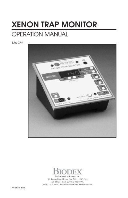
3. Press to continue after resetting the threshold level.4. If a measurement is made which exceeds the threshold value, the devicewill beep seven times and display the measured concentration. Afterseven seconds, the device will continue counting. If the Xe-133 concentration is consistently higher than the threshold, the alarm will beepnearly constantly indicating that the activated charcoal trap needsto be replaced.5. To verify CAL factor, after Step #2, press . It should be “0”(default CAL factor). Press to exit.NOTE: When decimal point (DP) is displayed, system is in pCi/ml mode.The Xenon Trap Monitor must be in this mode to change the threshold.There is no DP in the Scaler mode.To change modes from pCi/ml to Scaler or Scaler to pCi/ml:1. Press and hold button.2. Press and release button, then release button.3. The unit is now in the other mode.RECORD KEEPINGAfter installing the Xenon Trap Monitor, a 10.0 microcurie Cs-137 checksource (#101-103) should be used to record a measurement. Periodicmeasurements will produce a log over time, which will indicate the device isoperating properly. This log can also include trap measurement results. Anew trap should not cause an alarm during a ventilation study. This can berecorded as a “Pass Level”. A dirty Xenon trap will cause values to be displayedthat indicate Xenon is passing through. These values can be recordedas a “Fail Level”.When using the check source, hold it directly on top of the overlay word“<strong>TRAP</strong>”. Press the TEST key and the Xenon Trap Monitor will count for 60seconds. The displayed value will be the number of counts, neglecting thedecimal point (example: 25.3 means 253 counts were recorded in the 60-second period). Record the number of counts.OPERATOR INTERFACENOTE: The pass/fail LEDs are not used on this system.PWR: Power port, plug power converter in this port to turn the Xenon TrapMonitor ON.POWER ON LED: This LED indicates when power is supplied to the monitor.Power-up diagnostics occur during a short interval after power is supplied.A long audio "beep," followed by a short beep indicates the diagnosticstest is complete. The PASS/FAIL LEDs are also on during the diagnosticstest. The decimal point should remain visible on the display to indicatethe pCi/ml measurement mode.- 5-
RESET: Press this button to manually reset any function in progress. Pressingreset causes the system to restart and run the diagnostics test again.BKGND: Press this button to initiate continuous background measurementmode. The LED will turn on and total counts will be saved every 20 minutes,indicated by a short beep. At least one 20-minute background measurementmust be made before initiating TEST or COUNT modes. BKGND mode maybe terminated without losing the most recent background information bypressing the TEST or COUNT buttons.TEST: This function can be used following an error to perform a one-minutecount. If the TEST button is pressed the unit counts for 60 seconds andshould, display a value between .7 and 1.5 when no radiation source ispresent. The TEST button can also be used to check calibration, using a 10microcuries check source as described under "Record Keeping."MAINTENANCEAs required, wipe the Xenon Trap Monitor with a clean, damp cloth.SPECIFICATIONSDimensions: 6" w x 7" l x 4" h (15.2 x 17.8 x 10.2 cm)Lead Shielding: .5" thick (1.3 cm)Input: 22 mm hose adapterDetector: Halogen Quenched GM Tube, 1.1 cm dia, 2 mg/cm2 mica windowVoltage: 500 volts regulatedButtons: Background, Test, Count, Reset, Display Test, Data Entry Mode,Threshold and Up and Down for ThresholdDisplay: Four-digit LEDReadings: pCi/mlSpeaker: Internal, beeps when displays resultBackground Count Time: 20 minutesPower: 18 volts, UL approved, external; 115 VAC power adapterWeight: 4.5 lb (2.1 kg)Authorized European Community Representative: Prothia, Paris, FranceTROUBLESHOOTING INFORMATIONWhen both the red and green lights blink continuously, there has been somekind of detected failure. A failure code will be displayed. A list of possiblefailure causes follows:1. After Power ON, - Xenon Trap Monitor failed self-diagnostic test. Thefailure indication will be preceded by 1 to 6 beeps indicating the followingproblems:1 beep – GM tube in continuous conduction2 beeps – GM tube voltage not within limits3 beeps – Count flip-flop is not responding to reset4 beeps – Count registers are not responding to reset5 beeps – Count register does not respond to test count interrupt6 beeps – Program memory Checksum has changed since manufacture- 6-
2. After Background Error Interpretation1.0 GM Tube is in continuous conduction1.1 Background count greater than limit. Try to lower background byremoving any sources in the area or relocating the Xenon Trap Monitorto another location. Repeat the background test.1.2 Background test less than the limit which may indicate a defective tube.3. After Calibrate Error Interpretation2.0 GM Tube is in continuous conduction.2.1 GM count too high, use a lower activity source.2.2 Invalid background value is stored in memory making it impossible todetermine sensitivity. Return to step 1 and perform the background test,then redo Calibration.2.3 Calibration count rate is less than the background rate. Return tostep 1 and perform the background test, then redo Calibration.4. After Threshold Error Interpretation4.0 Threshold times sensitivity too large, lower threshold.4.1 Threshold times sensitivity too large, lower threshold.4.2 Count time is undefined, increase threshold.4.3 Threshold times sensitivity too large, lower threshold.4.4 Threshold times sensitivity too large, lower threshold.4.5 Count time greater than 30 minutes, increase threshold.5. After Count Error Interpretation3.0 Gm Tube in continuous conduction.3.1 Count rate is less than the background count rate. Return to step 1and perform the background test, then redo calibration.3.2 Invalid background value is stored in memory making it impossible todetermine the kdpm. Return to step 2 and perform the calibrationmeasurement.3.3 Invalid calibration factor is stored in memory, making it impossible todetermine kdpm. Press ENTER and a number will be displayed. Thisnumber should be zero in order for the XTM to apply the correct defaultcalibration factor. If this number is not zero, change it to zero using theUp/Down digit buttons, then press THRESHOLD to save it. PressRESET, and try to count again. If the number is zero and this error stilloccurs, a manual recalibration is required.5.0 GM count overflow, increase threshold to decrease time5.1 Decrease threshold5.2 Decrease threshold6. Service information: If the failure indication occurs at item 1 above, theWipe Test Counter should be returned for service. To return the system,or for additional service help/information, contact:Biodex Medical Systems, Inc.Service Department20 Ramsay RoadShirley, NY, 11967-4704Phone: (800) 224-6339FAX: (631) 924-8355- 7-
Certified Quality Management System<strong>BIODEX</strong>Biodex Medical Systems, Inc.20 Ramsay Road, Shirley, New York, 11967-4704Tel: 800-224-6339 (Int’l 631-924-9000),Fax: 631-924-9241 Email: info@biodex.com, www.biodex.com


