HOT - Titan Air
HOT - Titan Air
HOT - Titan Air

Create successful ePaper yourself
Turn your PDF publications into a flip-book with our unique Google optimized e-Paper software.
A I RI N C O R P O R A T E DOPERATING AND SERVICE MANUALSerial Number: _______For technical service or repair,FIRST CALL - INSTALLING CONTRACTOR:
AIRINCORPORATED24 MONTH WARRANTY<strong>Titan</strong> <strong>Air</strong>, Inc. hereby warrants its products against defects in material andworkmanship for a period of (24) twenty four months from date of shipment.Start up checklist is due back within (30) thirty days of start-up or 120 days from dateof delivery for 24 month warranty to be effective. After (30) thirty days, and up until (60)sixty days, a (12) twelve month warranty will be observed. All warranties are null andvoid if start up checklist is not received within (60) sixty days from start-up or 120 daysfrom date of delivery. NO EXCEPTIONS WILL BE MADE.<strong>Titan</strong> <strong>Air</strong>, Inc. reserves the right at <strong>Titan</strong> <strong>Air</strong>, Inc.’s option, to replace or repair free ofcharge, any part proven by <strong>Titan</strong> <strong>Air</strong>, Inc. to be defective. Prompt notification ofdefective part must be given to <strong>Titan</strong> <strong>Air</strong>, Inc. and defective part must be returned freightprepaid within (30) thirty days of notification.WARRANTY INCLUDES ONLY PARTS SUPPLIED BY TITAN AIR, INC.INCIDENTAL COSTS AND LABOR CHARGES SHALL BE THE RESPONSIBILITY OFOTHERS. This warranty does not cover fuses, belts, filters or water damaged partswhich are the result of improper storage or installation.This warranty is void in event the product is improperly installed and/or operatedunder conditions other than normal published ratings, improperly maintained, misused ornot in compliance with applicable codes or not in accordance with <strong>Titan</strong> <strong>Air</strong>, Inc.’soperating instructions.This warranty is void if attempts to correct or repair any alleged defective part orparts are made by unauthorized personnel without <strong>Titan</strong> <strong>Air</strong>, Inc.’s written approval.In no event shall <strong>Titan</strong> <strong>Air</strong>, Inc. be held liable for any damage, incidental orconsequential, arising from the installation, performance or operation of the product.This warranty supersedes, voids, and/or is in lieu of any other verbal or writtenunderstanding which may not be in total accordance with this expressed warranty.Warranted parts must be returned to <strong>Titan</strong> <strong>Air</strong>, Inc. within 60 days to receive credit.PURPOSE / APPLICABILITYThis manual is intended to provide installation, operating and service information on<strong>Titan</strong> <strong>Air</strong>’s TA Series H.O.T. (High Outlet Temperature) air make-up units. Other typesof equipment including TAP Series H.O.T. units are covered in other manuals.A packet of reference materials for a specific unit (tracked by its Serial Number) isgenerally included with this Operating and Service Manual. The reference materialsinclude Unit Specifications, Parts Lists, Gas Train and Burner Specifications, ElectricalSchematic, and a Sequence of Operation. A start up checklist is also included in thispacket. Review the reference materials for a specific unit and note any optionalequipment or controls which are not specifically addressed in this manual prior toattempting start-up or service work.The information and recommendations contained in this publication are based ongeneral observation and are not intended to supplant requirements of federal, state orlocal codes having jurisdiction. These codes should be reviewed before installation ofequipment. All units must be installed in accordance with national, state or local codes.It is the responsibility of the purchaser at the time of order, to specify any and allcode or insurance requirements that may dictate the addition of components to theequipment in order to comply with those requirements.Only qualified personnel who have experience with the installation and operation ofindustrial/commercial direct fired equipment should attempt to service <strong>Titan</strong> <strong>Air</strong>equipment.1
AIRINCORPORATEDPageWARRANTY 1TABLE OF CONTENTS 2GENERAL INFORMATION 3‣ Equipment Arrival‣ ComponentsAIR FLOW SWITCH OPERATION 7INSTALLATION 8‣ Installation and Field Wiring OverviewTYPICAL ASSEMBLY DRAWINGS 11MAINTENANCE 14FLAME FAIL DIAGNOSTICS 17START-UP PREPARATION 19VALVE LEAK TEST 20SPECIFIC EQUIPMENT DETAILS‣ Unit Specification‣ Unit Drawing‣ Sequence of Operation‣ Parts / Legend Sheet‣ Schematic‣ Start-Up Procedure‣ Troubleshooting (optional)pages not numberedNote that operating and service manuals are occasionally requested prior to productionof a unit. These manuals will be marked “Pre-Production Release” on the front cover.The final copy of the operating and service manual for a specific unit will be sent with theunit. Additional copies of the manual for a specific unit are available.A detailed unit specification sheet, parts/legend sheet, schematic, sequence of operationand start-up procedure are provided in the start-up section of each operating and servicemanual generated for a specific unit. Selected vendor cut sheets on components willalso be included.2
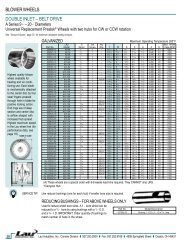
AIRINCORPORATEDEQUIPMENT ARRIVALWhen the air make-up unit arrives, be sure to inspect for shipping damage. Theequipment was thoroughly inspected before leaving the factory and the driver signed forit. Read the bill of lading and verify that all of the items listed are accounted for. Anydamaged or missing items should be reported to the transporter immediately. DO NOTSEND DAMAGED FREIGHT BACK TO TITAN AIR! All claims must be filed with thetransporter. Be sure to take photographs and get the drivers signature to confirm thedamage. The driver will have a number for you to call to file a claim. Request a writteninspection report from the claims inspector to substantiate any necessary claim. Be sureto open the unit access doors and inspect for internal damage.If for some reason you are unable to install the equipment immediately, be sure thatthe equipment is protected from the elements. Water damaged parts are not covered by<strong>Titan</strong> <strong>Air</strong>’s warranty. If the equipment is stored for an extended length of time, be sure tocompletely check over the unit for any internal damage which may have been caused byexcessive condensation. Also check for any damage caused by rodents, and be sure toeliminate any dust that may have built up on the components while the unit was instorage.CAREFULLY AND THOROUGHLY READ TITAN AIR’S PRODUCT WARRANTYEach unit is tested at the factory prior to shipping. Because we are not able tosimulate exact field conditions and sometimes actual conditions are different than whatwas stated on the order, you may need to make some adjustments in the field. This iswhy it is very important that only qualified personnel start-up and service <strong>Titan</strong> <strong>Air</strong>equipment. The start-up checklist (provided in packet with this manual) must be filledout and returned to <strong>Titan</strong> <strong>Air</strong> in order to validate equipment warranty.For a fee, <strong>Titan</strong> <strong>Air</strong> personnel will travel to the job site, supervise start-up and provideoperation and maintenance training for the equipment.BLOWERSThe typical blower(s) used in <strong>Titan</strong> <strong>Air</strong> equipment are AMCA rated industrial typeforward curve D.W.D.I. fans. Backward incline, backward airfoil, and plenum/plug fansare used occasionally. Models TA-109 through TA-136 utilize a single blower whilemodels TA-215 and TA-242 utilize twin blowers. All blower wheels are mounted on asolid, turned, ground and polished shaft. 9” and 12” blowers are supported withpermanently lubricated ball bearings. Larger blowers are supported by relubricatablepillow block ball bearings.MOTOR & DRIVERigid base, T-Frame, motors are utilized. The motor is mounted on an adjustableslide base. Variable pitch motor sheaves are typically provided to allow airflowadjustment if the motor is no larger than 30 Hp.3
AIRINCORPORATEDDIRECT FIRED HEATINGDirect fired burners are designed to operate in a fresh flowing airstream. Gas is feddirectly to the burner and the airstream provides the needed oxygen for combustion.A series of strategically sized and placed holes provide air to the combustion zone.See Figure 1The direct fired burner is designed to operate at an air velocity across the burner of2450 fpm with maximum manifold gas pressure as stated on unit rating plate. Twospeed H.O.T. units feature a damper with actuator and controls to maintain propervelocity across the burner profile as air volume changes. Single speed H.O.T. unitshave slide plates on either side of the burner to allow manual adjustment of the burnerprofile area.Because of the air pattern, air ports and kinetic energy of the air moving across theburner, the direct fired burner has the capabilities of a 30:1 turn down ratio. The high firerate can be as much as 30 times the low fire rate.4
AIRINCORPORATEDBURNER OPERATING PRINCIPLESThe direct fired burner is designed to operate in a cabinet of flowing fresh air. Fuelgas is fed directly to the burner; kinetic energy of the airstream furnishes combustion air.It will function properly at the design velocity and pressure associated with ventilatingsystems.The burner must be installed to fire with, and parallel to, the air flow. By virtue ofvelocity impact and suction generated by the diverging shape of the combustion baffles,air is induced through the air ports into the combustion zone. The air supply is constant,even though only that which mixes with the gas takes part in combustion.When a very small quantity of gas is admitted to the burner, sufficient mixing takesplace in the low fire slot where combustion takes place. Since the low fire zone iscontained within the burner casting it is effectively shielded from uncontrolled air entry.As the gas supply is increased the flame progresses into the intermediate fire zonewhere an additional supply of air is available. At higher or full capacity, mixing occurs atthe larger air ports of the high fire zone augmented by air flowing over the end of thebaffles.On a reduction of gas supply the reverse sequence takes place, the flame recedes toa location of lesser air supply until the low fire zone is reached. The burner is suitablefor a turndown range of approximately 30 to 1.AIR SUPPLYThe supply fan is typically positioned to draw air across the burner. <strong>Air</strong> flow acrossthe burner must be substantially straight (laminar) and velocity must be within the properrange to develop the desired turndown and capacity.When providing ventilation for an occupied space, the direct fired burner is designedto operate in an air make-up heater with all air crossing the burner taken directly fromoutdoors. The high outlet temperature mode is designed to serve an unoccupied spaceand some equipment will re-circulate air across the burner to achieve the high dischargetemperature.Total pressure rating of the blower includes allowance for the pressure drop throughthe primary air handling unit including the burner, together with pressure losses at theinlet screen, inlet damper, filters, outlet damper if used, plus the external pressure ratingof the system.BURNERSBurners are purchased in 6” and 12” straight lengths and 12” tee sections andare assembled to meet the BTU requirements of each piece of equipment.According to national safety standards, the following factors could influence safeoperation of a direct fired air make-up unit and must be interlocked to either prevent theburner from firing or shut it down if unsafe conditions occur.1. AIR SOURCE – If a damper is used, it must be interlocked to prove it isopen before the blower can start.2. BLOWER STARTER/VFD INTERLOCK – A contact proving that the blowerstarter is energized or VFD is operating must be incorporated to prevent burneroperation when the blower is not operating.3. AIR FLOW SWITCHES –Monitor the air flow (pressure drop) across the burner.The switches (one high differential and one low differential) will not allow burner tooperate if air pressure drop across burner is outside of the high and low set points.5
AIRINCORPORATED4. HIGH TEMPERATURE LIMIT – A manual reset high temperature limit controlmust be utilized to prevent high temperature situations caused by excessive fuelpressure or lack of air flow.5. FLAME SAFEGUARD – Monitors the combustion process during ignition andoperation for safe conditions.6. HIGH GAS PRESSURE SWITCH – Monitors gas pressure to the burner. Thisde-energizes the burner in the event gas pressure increases above its set point.The burner’s design and flexibility, coupled with proper controls, make direct fired airmake-up equipment the safest and most efficient method of tempering outdoor air.GAS CONTROLS<strong>Titan</strong> <strong>Air</strong> TA Series equipment is constructed to meet A.N.S.I Z83.4/CSA 3.7-1999standards. Components in the gas delivery manifold on standard equipment include:two manual shut-off valves, gas pressure regulator, two safety shut-off valves and anelectronic gas modulating valve. The pilot control includes a shutoff valve, gas pressureregulator and a pilot solenoid.ELECTRIC/ELECTRONIC CONTROLS<strong>Titan</strong> <strong>Air</strong> H.O.T. units typically come standard with the following items: disconnectswitch, starter and overload assembly(s) or variable frequency drive(s), control powertransformer (if a 3 wire system), air proving switches, high temperature limit, electronicflame safeguard and electronic flame modulation with remote setpoint adjustment. Manyother options including low temperature limit, inlet duct stat, and operating lights areavailable.CABINET<strong>Titan</strong> <strong>Air</strong> TA series equipment comes with either a galvanized finish or a paintedfinish. In both cases, the minimum gauge metal used is 18 ga.6
AIRINCORPORATEDBURNER PROFILE AIR PRESSURE DROPANSI standards, Z 83.4/CSA 3.7 M99 & Z 83.18-2000, require manufacturers tomonitor air moving across the burner for both high and low conditions. <strong>Titan</strong> <strong>Air</strong> utilizesair pressure drop across the burner to satisfy this requirement.Certification testing demonstrated that the burner will function properly between alow pressure drop of 0.2" w.c. and high pressure drop of 0.95" w.c. The standards alsomandate that the switches cannot be adjustable. This makes air pressure drop acrossthe burner profile a very important factor at initial start up.The design burner pressure drop at standard air conditions is 0.60” w.c. and willchange as the temperature of outside air increases or decreases from 70°F. In order forthe burner to operate within the range of the air flow monitoring switch set points, thepressure drop should be as close to 0.60” w.c. as possible.<strong>Air</strong> pressure drop across the burner profile is dependent on OA temperature. Whenthe burner is off, pressure drop will climb significantly during cold weather. The burner isalways off on initial start-up. Therefore, if the burner profile air pressure drop is above0.70” w.c. during a warm weather start-up, it may exceed 0.95” w.c. during a coldweather start-up in northern regions. Such a high air pressure drop would open the highairflow switch and prevent burner ignition.The following chart will aid in equipment set up at outside air temperatures differentfrom 70°F when the unit is operating with the burner off. The chart gives pressure drops,at various temperatures, equivalent to 0.60” w.c. at 70°F.Note that two speed H.O.T. units feature controls to maintain pressure drop acrossthe burner as air volume changes. Either high speed and low speed mechanicaladjustments of damper actuator travel or a dual pressure switch assembly are used tocontrol burner air pressure drop. Burner profile air pressure drop should be measuredon high speed with the burner profile dampers near the full open position. If the burnerprofile dampers open less than 50% on high speed, the unit is probably delivering lessthan full rated airflow.OATempBurner Profile <strong>Air</strong> Pressure Drop at Various OA Temperatures (Burner Off)BurnerProfile DropOATempBurnerProfile DropOATempBurnerProfile Drop-40 0.76 10 0.68 60 0.61-35 0.75 15 0.67 65 0.61-30 0.74 20 0.66 70 0.60-25 0.73 25 0.66 75 0.59-20 0.72 30 0.65 80 0.59-15 0.71 35 0.64 85 0.58-10 0.71 40 0.64 90 0.58-5 0.70 45 0.63 95 0.570 0.69 50 0.62 100 0.575 0.68 55 0.62 105 0.567
AIRINCORPORATEDCURBING (OUTDOOR MOUNTING)The use of a full perimeter curb or mounting rails under the heater is recommended.The only openings in the roof should be for the supply air duct, return air duct (ifrequired), gas and electrical connections (if applicable). These openings must be sealedproperly after installation. <strong>Titan</strong> <strong>Air</strong> ships all curbs unassembled and un-insulated.Installing contractor supplies gaskets, cant strips, insulation, etc.GAS PIPINGGas piping must be sized and installed in accordance with applicable codes. It mustbe able to deliver the specified CFH and gas pressure at full flow. Refer to unitnameplate or unit specification sheets for specified CFH and gas pressure.Care must be taken with the gas piping to prevent problems at start-up and laterduring operation. Before the union between the supply line and the unit is connected,the supply line should be cleaned out to remove any foreign material (dirt, rust, metalshavings, etc.).Refer to unit nameplate to determine the minimum gas supply pressure required toattain the maximum specified gas.All suitable gas controls, regulators and valves (equipped with a diaphragm) in thisdevice are furnished with an ANSI approved vent limiter. If local codes require thesecomponents be vented to the outside, it is the responsibility of the installing contractor.The heater and its individual shut off valve must be disconnected from the gassupply piping system during any pressure testing in excess of ½ PSIG.The heater must be isolated from the gas supply piping system by closing itsindividual shut off valve during any pressure testing of the supply system at pressuresequal to or less the ½ PSIG.During start-up, the technician should perform a gas leak check on all valves andpiping during the heater’s normal operation.DUCTWORKDuctwork must be sized and installed in accordance with applicable codes andstandards. A size variation may exist from recommended duct size to unit flange size.Recommended duct size applies to the size of the duct at the connection to theequipment. A properly designed duct transition from the blower outlet to a larger duct isrecommended for long ducts or ducts with numerous elbows.On heaters mounted outdoors, discharge ductwork should be insulated to minimizecondensation during the “off” cycle in cold weather. A fresh air intake hood with birdscreen is required. Discharge duct should be common to both blowers on twin blowerunits. Individual ducts for each blower are not recommended.On a heater mounted indoors with through the roof intake, a “mushroom” type intakehood is recommended to prevent moisture entrainment. When using “through the wall”intake duct, the intake louver should have adequate moisture baffling characteristics. Allintake ductwork exposed to the heated space should be insulated.9
AIRINCORPORATEDSOUND CONTROLFlexible connectors are recommended on at least one ductwork connection.Vibration isolators that mount between the unit and support structure are optional andcan be supplied with the equipment for installation by others. Another option is internalisolation of the blower/motor assembly with internal flexible connections between theblower housing and the unit structure.Appropriate insulation on the interior of ductwork significantly reduces sound levels.DISCHARGE TEMPERATURE SENSOR BULB INSTALLATION & WIRINGThe installing contractor may be responsible for field installation of the dischargetemperature sensor. Field installation of the discharge temperature sensor in thedischarge ductwork results in a better measurement of the average supply airtemperature. For paint booth applications, the sensor should typically be located asclose to the booth’s supply air plenum as possible. Utilize shielded cable for fieldinstalled discharge sensor wiring.FIELD WIRINGPower supply wiring should be routed from a dedicated branch circuit per schematic.Depending upon how the equipment was ordered, a single point power connection maybe subdivided to individual loads or multiple power supply circuits may be required.If an intake or discharge damper was ordered as a loose accessory, it will have to bemounted and the actuator must be wired. The remote panel must be mounted in aconvenient location and wired to the unit. Interlocks between the exhaust, unit andpossibly spray booth will have to be connected by field wiring.Carefully review the schematic and associated schematic symbol legend. Note thatlegend may be on the parts/legend sheet rather than on the schematic.Many codes require that low voltage wiring be routed in separate conduit from linevoltage wiring. If low voltage wiring is routed with 120 VAC control voltage wiring, itmust be placed in shielded cable(s) with appropriate insulation rating. Even if lowvoltage wiring is routed in separate conduit, very low voltage sensor outputs andactuator control signals should be routed in shielded cable.NOTE: All field wiring must conform to N.E.C. and/or any state or local codes.SUPPORT OF ACCESSORIESMost <strong>Titan</strong> <strong>Air</strong> equipment is supplied with loose accessories (i.e. damper, hood,discharge diffuser or filter section). If an intake hood is supplied by others, the designshall minimize entry of snow/rain and include an intake screen to meet ANSI standards.Intake accessories on large equipment may be shipped in two pieces for field assembly.Two damper actuators may need to field wired on large equipment as well.It is the responsibility of the installing contractor to support accessory items from arigid point or points to ensure solid mounting.POST INSTALLATIONCaulking is required between all parts prior to assembly and seams must bere-caulked after assembly. <strong>Air</strong> make-up units shipped in multiple sections willinclude a high quality caulk tape and caulk tubes. Caulk tape is applied betweensections with exterior caulking applied after the unit sections have been joined.Sealing integrity should be rechecked on a yearly basis.Water damaged parts are not covered by <strong>Titan</strong> <strong>Air</strong>’s warranty.10
AIRINCORPORATED11
AIRINCORPORATED12
AIRINCORPORATED13
AIRINCORPORATEDGENERAL MAINTENANCEAs with any equipment or machinery, a maintenance program should beimplemented. A well maintained unit will perform efficiently for many years.Equipment maintenance should include the following:1. Check filters and clean or replace as needed.2. Lube bearings.3. Check belts and belt tension.4. Check all hardware (bearings, etc.) for tightness.5. Check settings for all controls.6. Check duct connections for leaks.7. Re-caulk seams if needed.8. Check burner and flame rod - clean if necessary.9. Perform complete start-up procedure once per year (prior to heating season).FILTERSDirty or clogged filters will restrict air flow which in turn affects the burner operation.Therefore, it is necessary to check filters on a regular basis. Cleanable filters can beremoved from the filter rack and sprayed with a low pressure water. Always spray thesefilters in the opposite direction to air flow and apply new coating to filters when dry.BURNERMaintaining the pilot assembly is essential to reliable operation. During pre-heatingseason maintenance, the burner should be lit numerous times to confirm reliability. Ifignition system components require servicing, pay attention to the following:1. Handle porcelain spark rod and flame rod with care. Small cracks lead tointermittent ignition problems.2. Midco burners utilize the pilot gas tube as a ground point for the ignition rod.Keep this grounding point free from scale or other contaminant build-up.3. Ignition wire routing should remain separated from sheet metal cabinet tomaintain optimal spark strength.4. Dielectric grease is utilized inside of the ignition and flame sensor connectionboots to limit potential for moisture in the connection.5. Maintaining low pilot regulator output pressure typically produces reliable ignition.Excess pilot pressure creates a gas rich region that will not ignite consistently.6. The pilot solenoid is disabled following main flame ignition. The low fire settingmust be high enough to maintain a proper amplified flame rectification signal.Check that burner baffles are firmly attached to each other and to burner casting. Donot use excessive force on screws in casting. Clean baffles with wire brush if needed.Burner orifices may need to be re-drilled due to rust or other build-up. Burners withaluminum castings will rarely require orifice cleaning. Use drill bit sizes listed below.Fuel Type Burner Model Orifice SizeNatural Gas Eclipse AH-MA 2.4 mm BitNatural Gas Midco HMA-2 or 2A 1/8” BitLP Gas Eclipse AH-MA 2.0 mm BitLP Gas Midco HMA-2 or 2A 1/8” BitLow Fire <strong>Air</strong> Ports Midco HMA-2 or 2A #43 Bit14
AIRINCORPORATEDBELT TENSIONProper sheave alignment and belt tension are critical to belt and bearing service life.Incorrect belt tension or misalignment of sheaves can cause any of the following:1. Premature failure of bearings.2. Premature failure of belts.3. Reduced air volume.4. Noise and vibrations.Each <strong>Titan</strong> <strong>Air</strong> unit has as standard equipment an adjustable motor base. To adjustthe belt tension, loosen the motor hold down bolts and adjust the slide base withadjusting bolt(s) on the end of the base (larger bases will have 2 adjustment bolts).Loose belts will slip. Excessive belt tension will shorten belt and bearing life. Use a belttension tester and associated tables to determine proper tension. Re-tension after thefirst day of operation with new belts and periodically thereafter.Common belt tension gauges will specify a force required to produce a deflection of1/64” per inch of span. The force required to achieve this deflection is typically in therange of 3 lbs for A-belts, 5 lbs. for B-belts, and 15 lbs. for 5V belts. See Figure 1 below.Note that optimal belt tension is the lowest tension at which the belts will not slipunder peak load. Peak load typically occurs at start-up.SHEAVE ALIGNMENTWith the use of a straight edge, sheave alignment can be checked quickly andaccurately. One of the sheaves will have to be loose on its shaft in order to makeadjustment. Adjust until all 4 points are in contact with the straight edge (see Figure 2).Repeat on the other side of sheaves and then re-tighten.If a face width variation exists, measure the difference between each side of thenarrowest sheave and adjust until both sides are an equal distance from the straightedge.Motor BaseDeflection 1/64"per inch of spanForceFigure 1Straight Edge1 2 3 4Figure 215
AIRINCORPORATEDBLOWER BEARINGSBearings must be checked during each periodic maintenance inspection. Bolts andset screws should be checked for tightness and the bearings may need lubrication. Thefollowing is intended only as a guide to aid you in setting up your own scheduleLUBRICATION GUIDE FOR BLOWER BEARINGSOperating conditions Bearing Temp. (°F) Grease IntervalClean 32 - 120 6 - 10 months120 - 150 1 - 3 months150 - 200 1 - 4 weeksDirty 32 - 150 1 - 4 weeks150 - 200 Daily - 1 weekMoisture 32 - 200 Daily - 1 weekMOTOR BEARINGSMotor bearings in a clean environment should be lubricated every 2 to 3 years.Under more severe conditions of dirt or moisture, lubrication may be required every 6months to 1 year. Typical motor bearing lubrication procedure follows:1. Remove fill and drain plugs.2. Clean drain port of hard grease (with wire if necessary).3. Add grease (cavity should be no more than ½ full.).4. Start motor and let run for 10 minutes.5. Wipe off any drained grease and replace fill and drain plugs.Avoid adding an excessive amount of grease since this a common cause of motorfailure.BLOWEREnsure that blower hub is securely fastened to shaft. Inspect blower wheel andblades for signs of damage or cracks. Clean blades if necessary to maintain properbalance and performance. Avoid use of excessive grease on blower bearings that cancoat fan blades and attract dirt16
AIRINCORPORATEDFIREYE MICRO M SERIES LED INDICATING LIGHTS – STANDARD OPERATION‣ Operating Control - Energized whenever the burner control switch is on and poweris applied to terminal #7 in the flame safeguard.‣ Interlock - Illuminated solid when power is applied on terminal # 6 in the flamesafeguard to indicate that the air flow switch and other control & limit switches areclosed. This light flashes once per second if the user has selected the fan-onlymode (summer) or if an airflow switch or other safety circuit switch is open.‣ PTFI - Illuminated only during the pilot trial for ignition period.‣ Flame - Illuminated when flame signal is detected.‣ Alarm - LED will flash once per second when an alarm condition is detected.FIREYE MICRO M SERIES LED INDICATING LIGHTS – ALARM MODESymbol LegendFlashing Light Solid Light Light OffLockout Description OPR CNTL INTRLK PTFI FLAME ALARMLine Frequency Noise DetectedFlame Fail – PTFIFault UnknownAmplifier High Count FailFlame Fail – MTFIFalse Flame – StandbyInterlock OpenInterlock ClosedChassis OptoFlame Fail – AutoCheck ChassisCheck ProgrammerAmplifier Auto Check FailCheck Blown FuseCheck Sensor17
AIRINCORPORATEDLine Frequency Noise Detected - At start up, the MICRO M measures the AC line todetermine if the input is 50 Hz or 60 Hz and set its flag accordingly. As the system isrunning, line frequency is constantly monitored. Outside interference causing amomentary shift in line frequency could be from SCR controls, VFD’s, etc.Flame Fail - PTFI - No flame signal present at the end of pilot trial for ignition period.Fault Unknown - A catch all message when, under certian high noise conditions, thelockout message may become garbled and not translatable into any existing messageAmplifier Count Fail - A message used to detect a failed amplifier module that wouldgenerate an inordinate amount of pulses to micro computer, usually due to a shortedtransistor or oscillating electronic filterFlame Fail - MTFI - No flame signal present during main burner trial for ignition period.Flame Fail - Standby - Flame signal present, for a constant 60 seconds, while control isin standby or off conditionInterlock Open - Interlock safety circuit (terminal #6) has been detected open for longerthan ten minutes during the purge cycle or during main flame period on MEP 562.Interlock Closed - If selected by dip switches, air flow or interlock switch (terminal #6) isclosed 30 seconds after the start of a cycle or when terminal #7 is closed. <strong>Titan</strong> <strong>Air</strong> doesnot use this function.Chassis Opto - Opto coupler located on chassis has been found to be defective. Optocouplers are checked every 1/2 cycle of the AC main(s) to ensure they are off during thenegative 1/2 cycle.Flame Fail Auto - If dip switches selected for non-recycle, no flame is detected duringthe run cycle or main flame period.Check Chassis - At beginning of cycle terminal #5 is energized.Check Programmer - At beginning of cycle terminal #3 is energized or an internaldiagnostics test for the Micro controller has failed.Check Amplifier - Diagnostic problem with amplifier has been found.Amplifier Auto Check - The amplifier is checked every 8 seconds by the micro computerto assure it is responding properly.Check Blown Fuse - At the end of pilot try for ignition, no flame is detected and no poweris present on terminal #3, indicating the fuse, located on chassis, is blown.Check Scanner - The UV self check scanner (UV equipped units only) is producingflame pulses during the shutter closed period due to a malfunctioning shutter or a runawayUV tube18
AIRINCORPORATEDGENERAL START-UP INFORMATIONEven though <strong>Titan</strong> <strong>Air</strong> equipment is tested at the factory, it is not the type ofequipment you can throw the switch and walk away from. A complete start-upprocedure must be performed.The factory cannot duplicate the conditions the equipment will see in the actualinstallation (i.e. gas pressure, static pressure, desired control settings, etc…). For thisreason there are field adjustments that have to be made. Performing a complete startupprocedure will help ensure that correct adjustments are made and correct operation isverified. A step-by-step start-up procedure is provided on subsequent pages. Whileworking through the start-up procedure, record information on the start-up checklist andreturn to <strong>Titan</strong> <strong>Air</strong> to validate the equipment warranty. The start-up checklist is providedon cardstock with <strong>Titan</strong> <strong>Air</strong>’s address pre-printed on one side.Because most component failures occur during start-up, it is very important that thefunction of every component be checked out during start-up. It is just as important thatthe start-up technician realize the malfunction of a component may be caused by otherfactors (i.e. air flow, gas pressure, field wiring, etc…) and should fully investigate acomponent malfunction and its cause before replacing the component.<strong>Titan</strong> <strong>Air</strong> checks out all returned components and has found approximately 70% ofreturned parts are in full operational condition. This history has proven that a little extratime invested in troubleshooting will often save the considerable investment in parts,time, and paperwork associated with replacing components.SUGGESTED TOOLS AND INSTRUMENTS NEEDED FOR START-UP:Volt/Ohm MeterAmmeterTachometerThermometerGas pressure gauge (-10” to 0 to +10” of water column typical scale)<strong>Air</strong> differential pressure gauge (-2” to 0 to +2” of water column typical scale)Standard Hand Tools.Additional items for Maxitrol Series 14 or 44 temperature controls:‣ 10,000 Ohm potentiometer‣ ½ watt, 10,000 Ohm resistor‣ ½ watt, 2,000 Ohm resistorAdditional items for FX Series temperature controls:‣ 1,070 Ohm resistor (supplied)19
AIRINCORPORATEDValve Leak TestThis is a test for checking the closure tightness of the gas safety shutoff valve. It should beperformed by trained and experienced technicians. This test should be part of the scheduledinspections and maintenance procedures.1) Close the upstream manual gas valve.2) Make sure manual test cock on leak test assembly is closed.3) Remove the test plug on leaving side of gas valve.4) Close the downstream manual gas valve.5) Open the upstream manual gas valve.6) Through the safety system enable the gas valve momentarily.7) Immerse a ¼” tube vertically into a jar of water.8) Slowly open the test cock on the leak assembly.9) Once the rate of bubbles through the test assembly stabilizes, count the number of bubblesappearing during the ten second time frame. Each bubble is approximately 0.001 cfh.10) Do this test for each shut off valve.Reference below leak test assembly and leakage rate chart.Pipe Size (in) Medium AllowableLeakage SCCHMax. # of Bubblesin 10 Sec.Min. # of sec. for10 bubbles3/8 & 1/2 .64 gas 294 7 131.57 LP 188 4 20.43/4 & 1 .64 gas 301 7 12.71.57 LP 192 5 19.91-1/4 & 1-1/2 .64 gas 532 13 7.21.57 LP 341 8 11.22 .64 gas 578 15 6.61.57 LP 370 9 10.31-1/2 .64 gas 752 19 5.11.57 LP 481 12 83 .64 gas 925 24 4.11.57 LP 592 15 6.520