
Create successful ePaper yourself
Turn your PDF publications into a flip-book with our unique Google optimized e-Paper software.
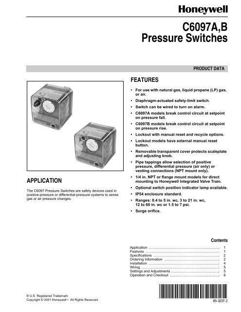
<strong>C6097</strong>A,B<strong>Pressure</strong> <strong>Switch</strong>esFEATURESPRODUCT DATAAPPLICATIONThe <strong>C6097</strong> <strong>Pressure</strong> <strong>Switch</strong>es are safety devices used inpositive-pressure or differential-pressure systems to sensegas or air pressure changes.• For use with natural gas, liquid propane (LP) gas,or air.• Diaphragm-actuated safety-limit switch.• <strong>Switch</strong> can be wired to turn on alarm.• <strong>C6097</strong>A models break control circuit at setpointon pressure fall.• <strong>C6097</strong>B models break control circuit at setpointon pressure rise.• Lockout with manual reset and recycle options.• Lockout models have external manual resetbutton.• Removable transparent cover protects scaleplateand adjusting knob.• Pipe tappings allow selection of positivepressure, differential pressure (air only) orventing connections (NPT mount only).• 1/4 in. NPT or flange mount models for directmounting to Honeywell Integrated Valve Train.• Optional switch position indicator lamp available.• IP54 enclosure standard.• Ranges: 0.4 to 5 in. wc, 3 to 21 in. wc,12 to 60 in. wc or 1.5 to 7 psi.• Surge orifice.ContentsApplication ........................................................................ 1Features ........................................................................... 1Specifications ................................................................... 2Ordering Information ........................................................ 2Installation ........................................................................ 4Wiring ............................................................................... 5Settings and Adjustments ................................................. 5Operation and Checkout .................................................. 6® U.S. Registered TrademarkCopyright © 2001 Honeywell • All Rights Reserved65- 0237- 2
<strong>C6097</strong>A,B PRESSURE SWITCHESSPECIFICATIONSModels:<strong>C6097</strong>A <strong>Pressure</strong> <strong>Switch</strong>: Breaks a circuit when pressure fallsto scale setting. See Table 1.<strong>C6097</strong>B <strong>Pressure</strong> <strong>Switch</strong>: Breaks a circuit when pressurerises to scale setting. See Table 1.Table 2 shows switch ratings and Table 3 shows alternateelectrical ratings when used with Honeywell FlameSafeguard Programmers.Minimum Ambient Temperature: -40°F (-40°C).Maximum Ambient Temperature: 140°F (60°C).Connections (Depending on Model):1/4-18 NPT tapping for main or high-pressure connection.1/8-27 NPT tapping for vent or low-pressure connection(air only).Flange mount for connection to Honeywell Integrated ValveTrain (internal vent only, no external connections).Scale Range:0.4 to 5 in. wc (0.10 kPa to 1.25 kPa).3 to 21 in. wc (0.75 to 5.23 kPa).12 to 60 in. wc (3.0 kPa to 15 kPa).1.5 to 7 psi (10.3 kPa to 48 kPa).Dimensions: See Fig. 1 and 2.13/32(11)1-3/32 (28)2-21/32 (68)2-23/32 (69)1-3/4 (45)27/32(22)HOLE31/32(25)25/32(21)2-1/4(57)3-3/16(81)2-13/32(61)1-17/32(90)HOUSING2-21/32 (68)15/32 (12)2-23/32 (69)INDICATORApprovals:Underwriters Laboratories Inc. listed.Canadian Standards Association listed.Factory Mutual: Approved.Industrial Risk Insurers: Acceptable.CSD-1 AFB: Acceptable.Accessories:32003041-001 <strong>C6097</strong> Cover for manual reset models.32003040-001 <strong>C6097</strong> Cover for recycle models.32003039-001 Position Indication Lamp Kit.DIFFERENTIALCONNECTION1/8 NPTGAS CONNECTION1/4 NPT WITH DUST SEALTERMINAL DIAGRAM1 2 3NOFig. 1. <strong>C6097</strong> 1/4 in. NPT Mount dimensions in in. (mm).NCPCOMM17125ORDERING INFORMATIONWhen purchasing replacement and modernization products from your TRADELINE® wholesaler or distributor, refer to theTRADELINE® Catalog or price sheets for complete ordering number.If you have additional questions, need further information, or would like to comment on our products or services, please write orphone:1. Your local Home and Building Control Sales Office (check white pages of your phone directory).2. Home and Building Control Customer RelationsHoneywell, 1885 Douglas Drive NorthMinneapolis, Minnesota 55422-4386 (800) 328-5111In Canada—Honeywell Limited/Honeywell Limitée, 35 Dynamic Drive, Scarborough, Ontario M1V 4Z9.International Sales and Service Offices in all principal cities of the world. Manufacturing in Australia, Canada, Finland, France,Germany, Japan, Mexico, Netherlands, Spain, Taiwan, United Kingdom, U.S.A.65-0237—2 2
<strong>C6097</strong>A,B PRESSURE SWITCHESModel<strong>C6097</strong>A1004<strong>C6097</strong>A1012<strong>C6097</strong>A1020Operating<strong>Pressure</strong>Range0.4 to 5 in.wc3 to 21 in.wc3 to 21 in.wc<strong>C6097</strong>A1038 12 to 60in. wc<strong>C6097</strong>A1046 12 to 60in. wc<strong>C6097</strong>A1053 3 to 21 in.wc<strong>C6097</strong>A1061 3 to 21 in.wc<strong>C6097</strong>A1079 12 to 60in. wc<strong>C6097</strong>A1087 12 to 60in. wc<strong>C6097</strong>A1095 0.4 to 5 in.wc<strong>C6097</strong>A1103 1.5 to 7psi<strong>C6097</strong>A1111 1.5 to 7psi<strong>C6097</strong>A1129 1.5 to 7psi<strong>C6097</strong>A1137 1.5 to 7psi<strong>C6097</strong>A1210 0.4 to 5 in.wc<strong>C6097</strong>A1228 0.4 to 5 in.wc<strong>C6097</strong>B1002 12 to 60in. wc<strong>C6097</strong>B1010 12 to 60in. wc<strong>C6097</strong>B1028 3 to 21 in.wc<strong>C6097</strong>B1036 3 to 21 in.wc<strong>C6097</strong>B1044 1.5 to 7psi<strong>C6097</strong>B1051 1.5 to 7psi<strong>C6097</strong>B1069 3 to 21 in.wc<strong>C6097</strong>B1077 12 to 60in. wc<strong>C6097</strong>B1085 12 to 60in. wc<strong>C6097</strong>B1093 1.5 to 7psi<strong>C6097</strong>B1101 1.5 to 7psi<strong>C6097</strong>B1119 3 to 21 in.wcManual ResetDifferentialMaximumatMinimumSetpointa Acceptable media: Natural gas, liquid propane (LP) gas, and air.Table 1. <strong>Pressure</strong> <strong>Switch</strong> Model Selection.Non-Manual ResetDifferentialMaximumatMaximumSetpoint Nominal Maximum— — 0.16 in.wcDifferentialTypeMaximumRated<strong>Pressure</strong>(continuous)(psi)Reset Media a Setpoint<strong>Switch</strong>ManualAction at0.24 in. wc Additive 2.9 No <strong>Air</strong>/Gas Breaks N.O.to C.connectionon pressurefall.Comments1/4 in. NPTMount2.4 in. wc 4.2 in. wc — — 5.0 Yes <strong>Air</strong>/Gas 1/4 in. NPTMount2.4 in. wc 4.2 in. wc — — 5.0 Yes <strong>Air</strong>/Gas Flange Mount10 in. wc 12 in. wc — — 5.0 Yes <strong>Air</strong>/Gas 1/4 in. NPTMount10 in. wc 12 in. wc — — 5.0 Yes <strong>Air</strong>/Gas Flange Mount— 0.24 in.wc— — 0.24 in.wc0.48 in. wc 5.0 No <strong>Air</strong>/Gas 1/4 in. NPTMount0.48 in. wc 5.0 No <strong>Air</strong>/Gas Flange Mount— — 1.1 in. wc 2.4 in. wc 5.0 No <strong>Air</strong>/Gas 1/4 in. NPTMount— — 1.1 in. wc 2.4 in. wc 5.0 No <strong>Air</strong>/Gas Flange Mount0.6 in. wc 1.0 in. wc — — 2.9 Yes <strong>Air</strong>/Gas 1/4 in. NPTMount1.1 psi 1.4 psi — — 9.3 Yes <strong>Air</strong>/Gas Flange Mount1.1 psi 1.4 psi — — 9.3 Yes <strong>Air</strong>/Gas 14 in. NPT Mount— — 0.1 psi 0.3 9.3 No <strong>Air</strong>/Gas Flange Mount— — 0.1 psi 0.3 9.3 No <strong>Air</strong>/Gas 1/4 in. NPTMount— — 0.16 in.wc0.24 in. wc 2.9 No <strong>Air</strong>/Gas Flange Mount— — — — 2.9 Yes <strong>Air</strong>/Gas Flange Mount10 in. wc10 in. wc12 in. wc12 in. wc————Subtractive 5.05.0YesYes<strong>Air</strong>/Gas<strong>Air</strong>/GasBreaks N.C.to C.connectionon pressurerise.1/4 in. NPTMountFlange Mount2.4 in. wc 4.2 in. wc — — 5.0 Yes <strong>Air</strong>/Gas 1/4 in. NPTMount2.4 in. wc 4.2 in. wc — — 5.0 Yes <strong>Air</strong>/Gas Flange Mount1.1 psi 1.4 psi — — 9.3 Yes <strong>Air</strong>/Gas Flange Mount1.1 psi 1.4 psi — — 9.3 Yes <strong>Air</strong>/Gas 1/4 in. NPTMount— — 0.24 in.wc0.48 in. wc 5.0 No <strong>Air</strong>/Gas Flange Mount— — 1.1 in. wc 2.4 in. wc 5.0 No <strong>Air</strong>/Gas Flange Mount— — 1.1 in. wc 2.4 in. wc 5.0 No <strong>Air</strong>/Gas 1/4 in. NPTMount— — 0.1 psi 0.3 psi 9.3 No <strong>Air</strong>/Gas Flange Mount— — 0.1 psi 0.3 psi 9.3 No <strong>Air</strong>/Gas 1/4 in. NPTMount— — 0.24 in.wc0.48 in. wc 5.0 No <strong>Air</strong>/Gas 1/4 in. NPTMount3 65-0237—2
<strong>C6097</strong>A,B PRESSURE SWITCHESTable 2. <strong>Switch</strong> Ratings (Amperes).120/240 Vac, 50/60 HzInductive Full Load 3.0Locked Rotor 18.0Resistive 5.0Table 3. Alternate Electrical Ratings when used withHoneywell Flame Safeguard Programmers.DeviceIgnition TransformerPilot ValveMain Valve27/32 (22) HOLE5/8 (16)2-23/32 (69)PRESSURE INLETTERMINAL DIAGRAM1 2 3NONCPCOM1-1/4(32)1/32(1)Rating540 VA50 VA400 VA with 2-1/2 times inrush.2-1/4(57)2(52)2-21/32 (68)2-23/32 (69)2 (52)INDICATORM17124Fig. 2. <strong>C6097</strong> Flange Mount dimensions in in. (mm).INSTALLATIONWARNINGExplosion or Fire Hazard.Can cause severe personal injury, death orproperty damage.Observe all safety requirements each time a control isinstalled on a burner.When Installing this Product...1. Read these instructions carefully. Failure to followthem can damage the product or cause a hazardouscondition.2. Check the ratings given in the instructions and on theproduct to make sure that the product is suitable foryour application.3. Installer must be a trained, experienced servicetechnician.4. After installation is completed, check out productoperation as provided in these instructions.MountingNOTE:WARNINGElectrical Shock Hazard.Can cause serious personal injury or death.Disconnect power supply before beginning installation.More than one disconnection can be involved.On flange models, remove the label holding theO-ring in place and make sure O-ring seal is in placebefore mounting the pressure switch on the valve.The <strong>C6097</strong> models allow NPT or flange (directly to valve)mounting. The NPT models have a hexagonal fitting with a1/4 in. NPT tapping, which is the high pressure connection, indifferential applications. The bleed fitting is 1/8 in. NPTtapped. In differential pressure control applications using aironly, connect the lower pressure to the bleed fitting. See Fig. 1and Table 1. In applications using combustible gases, vent thebleed tapping according to applicable standard code orjurisdictional authority.<strong>C6097</strong> models with flange mount can be fitted directly toHoneywell Integrated Valve Train (model specific). See Fig. 2and Table 1. The flange mount models vent internally, with noexternal tap.Mount the <strong>C6097</strong>A,B in any position.Leak CheckAfter installation, perform a leak check on the pressure switch:1. Turn on main gas. Make sure gas has reached thepressure switch (e.g., high gas pressure switch)2. Check installation for gas leaks using a gas leakdetector or a soap solution.65-0237—2 4
<strong>C6097</strong>A,B PRESSURE SWITCHESWIRINGWARNINGElectrical Shock Hazard.Can cause serious personal injury or death.Disconnect power supply before beginning installation.More than one disconnection can be involved.Make sure that all wiring agrees with all applicable localcodes, ordinances and regulations. An opening is provided toaccommodate rigid conduit or armored cable for line voltageoperation (see Fig. 3 and 4). Do not overload the switchcontacts (see <strong>Switch</strong> Ratings in the Specifications section).The switching schematic is shown in Fig. 5.Fig. 4. <strong>C6097</strong> (recycle model) with cover removed.SETTINGS AND ADJUSTMENTS<strong>Pressure</strong> Setpoint AdjustmentTo adjust the pressure setting, turn the setpoint adjustmentdial (Fig. 3, 4 and 5) clockwise to increase thepressure setting and counterclockwise to decreasethe pressure setting.NOFig. 3. <strong>C6097</strong> (manual reset switch model)with cover removed.NC12C1<strong>C6097</strong>A BREAKS C-NO, MAKES C-NC ON PRESSUREFALL. MANUAL RESET MODELS LOCK OUT.2<strong>C6097</strong>B BREAKS C-NC, MAKES C-NO ONPRESSURE RISE AND LOCKS OUT.Fig. 5. <strong>C6097</strong> schematic.M171235 65-0237—2
<strong>C6097</strong>A,B PRESSURE SWITCHESOPERATION AND CHECKOUTOperationThe manual reset <strong>C6097</strong>A diaphragm actuates the snapactingswitch to break a control circuit and lock out whenpressure falls to the scale setting. The recycle <strong>C6097</strong>Amodels recycle automatically when the control circuit returnsto scale setting plus differential.The manual reset <strong>C6097</strong>B diaphragm actuates the snapactingswitch that breaks a control circuit and locks out whenthe pressure rises to the scale setting. The recycle <strong>C6097</strong>Bmodels recycle automatically when the control pressure fallsto the scale setting minus differential.Manual ResettingThe <strong>C6097</strong>A manual reset models lock out when pressurefalls to the scale setting and require manual resetting after thepressure rises to scale setting plus differential to resumenormal operation.The <strong>C6097</strong>B manual reset models lock out when pressurerises to the scale setting and require manual resetting afterthe pressure falls to scale setting minus the differential toresume normal operation.To reset, once normal operating pressure is restored, push thereset button in as far as it goes, then release.IMPORTANTLockout models cannot be made to recycleautomatically by permanently holding in thereset lever.Checkout<strong>C6097</strong> Gas Fuel Application1. Set cutoff pressure.2. Open main supply line. Depress reset lever on lockoutmodels until switch makes control circuit.3. Set controller and limit switch to call for heat.4. For <strong>C6097</strong>A: Close the manual gas shutoff valve.<strong>C6097</strong> should open control circuit when pressurereaches cutoff point.For <strong>C6097</strong>B: Open the manual gas shutoff valve, wait afew minutes for the pressure to rise; then lower thescale setting until the switch breaks control circuit andlocks out.5. For <strong>C6097</strong>A: Open the shutoff valve, return thepressure switch to its original setting and press the resetbutton (if necessary).For <strong>C6097</strong>B: raise setting to normal and press resetbutton (if necessary).6. Allow system to operate through at least one completecycle to make sure all components are functioningproperly.<strong>C6097</strong>A <strong>Air</strong> Application1. Set cutoff pressure.2. Turn on fan.3. Block fan inlet or filter area. <strong>Switch</strong> should break controlcircuit when pressure drops to cutoff point. Manual resetmodels lock out.4. Remove obstruction. Press reset lever (manual resetmodels) and allow system to operate through at leastone complete cycle to be sure all components arefunctioning properly.65-0237—2 6
7 65-0237—2
Home and Building Control Home and Building Control Honeywell International Honeywell Europe Honeywell Latin AmericanHoneywell Honeywell Limited-Honeywell Limitée Home and Building Control S.A. Region1985 Douglas Drive North 35 Dynamic Drive Honeywell Building 3 Avenue du Bourget 480 Sawgrass Corporate ParkwayGolden Valley, MN 55422 Scarborough, Ontario 17 Changi Business Park Central 1 1140 Brussels Suite 200M1V 4Z9 Singapore 486073 Belgium Sunrise FL 3332565-0237—2 G.R. Rev. 10-01Printed in U.S.A. on recycledpaper containing at least 10%www.honeywell.compost-consumer paper fibers.