Anritsu MS2667C Data Sheet - Mr Test Equipment
Anritsu MS2667C Data Sheet - Mr Test Equipment
Anritsu MS2667C Data Sheet - Mr Test Equipment

Create successful ePaper yourself
Turn your PDF publications into a flip-book with our unique Google optimized e-Paper software.
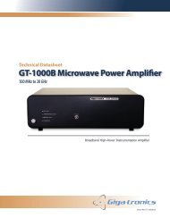
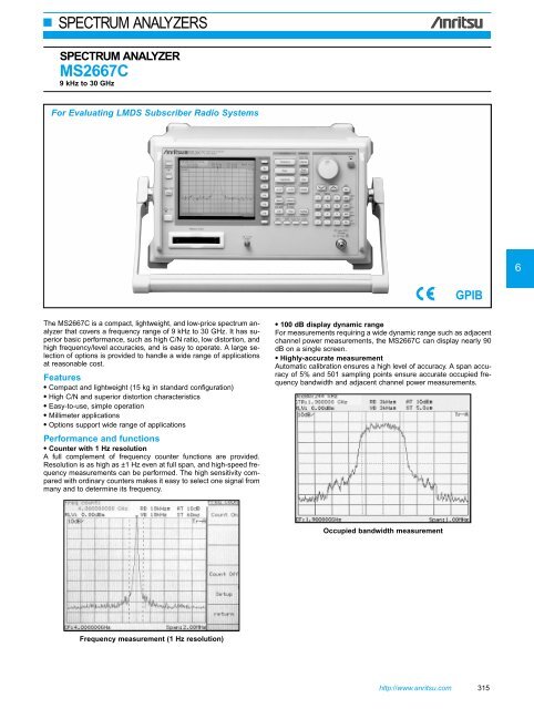
SPECTRUM ANALYZERS• Radio equipment evaluation functions (“measure” functions)A full range of functions including measurement of power levels, frequencies,adjacent channel power, and mask and time templatemeasurements are provided for performance evaluation of radioequipment. Key operation is simple and high-speed calculationsmake the measurement fast and efficient.Adjacent channel power measurementBurst average power measurementTime template measurementMask measurement• Zone sweep and multi-zone sweep functionsSweeps can be limited to zones defined by zone markers which resultsin reduced sweep time. This zone sweep function can be combinedwith “measure” functions such as “noise measure,” which candirectly readout the total noise power within the zone to reduce measurementtime greatly. The multi-zone sweep function enables up to10 zones to be swept.Channel power measurementMulti-zone sweep316 For product ordering information, see pages 4 – 10
SPECTRUM ANALYZERSSweepFunctionsSweep timeSweep modeTime domainsweep modeZone sweepTracking sweepNumber of datapointsDetection modeDisplayDisplay functionsStorage functionsFM demodulationwaveform displayfunctionInput connectorAuxiliary signalinput and outputSignal searchZone markerMarker →Peak searchMultimarkerMeasureSave/recallHard copyPTARS-232CGPIBCorrectionMemory cardinterfaceSetting range: 20 ms to 1000 s (manually settable, or automatically settable according to span, RBW and VBW)Accuracy: ±15% (20 ms to 100 s), ±25% (110 to 1000 s), ±1% (time domain sweep: digital zero span mode)Continuous, singleAnalog zero span, digital zero spanSweeps only in frequency range indicated by zone markerSweeps while tracing peak points within zone marker (zone sweep also possible)501NORMAL: Simultaneously displays max. and min. points between sample pointsPOS PEAK: Displays max. point between sample pointsNEG PEAK: Displays min. point between sample pointsSAMPLE: Displays momentary value at sample pointsDetection mode switching uncertainty: ±0.5 dB (at reference level)Color TFT-LCD, Size: 5.5 inch, Number of colors: 17 (RGB, each 64-scale settable), Intensity adjustment: 5 steps settableTrace A: Displays frequency spectrumTrace B: Displays frequency spectrumTrace Time: Displays time domain waveform at center frequencyTrace A/B: Displays Trace A and Trace B simultaneously. Simultaneous sweep of same frequency, alternate sweep ofindependent frequencies.Trace A/BG: Displays frequency region to be observed (background) and object band (foreground) selected from backgroundwith zone marker simultaneouslyTrace A/Time: Displays frequency spectrum and time domain waveforms at center frequency simultaneouslyTrace move/calculation: A → B, B → A, A ↔ B, A + B → A, A – B → A, A – B + DL → ANORMAL, VIEW, MAX HOLD, MIN HOLD, AVERAGE, CUMULATIVE, OVER WRITEDemodulation range: 2, 5, 10, 20, 50, 100, 200 kHz/divMarker displayAccuracy: ±5% of full scale (referenced to center frequency, DC-coupled. RBW: 3 MHz, VBW: 1 Hz, CW)Demodulation frequency response: DC (50 Hz at AC-coupled) to 100 kHz (range: ≤20 kHz/div, VBW: off, at 3 dB bandwidth)DC (50 Hz at AC-coupled) to 500 kHz (range: ≥50 kHz/div, VBW: off, at 3 dB bandwidth)∗RBW: ≥1 kHz to 3 MHz usableK-J, 50 ΩIF OUTPUT: 10.69 MHz, BNC connectorVIDEO OUTPUT (Y): 0 to 0.5 V ±0.1 V (typical, from lower edge to upper edge at 10 dB/div),0 to 0.4 V ±0.1 V (typical, from lower edge to upper edge at 10%/div), BNC connector∗75 Ω terminated at 100 MHz inputCOMPOSITE OUTPUT: For NTSC, 1 Vp-p (75 Ω terminated), BNC connectorEXT REF INPUT: 10 MHz ±10 Hz, –10 to +2 dBm (50 Ω terminated), BNC connectorREF BUFFERED OUTPUT: ≥0 dBm (50 Ω terminated), BNC connector1ST LOCAL OUTPUT: 4 to 7 GHz, ≥+8 dBm, 50 Ω, SMA-J connectorAUTO TUNE, PEAK → CF, PEAK → REF, SCROLLNORMAL, DELTAMARKER → CF, MARKER → REF, MARKER → CF STEP SIZE, ∆MARKER → SPAN, ZONE → SPANPEAK, NEXT PEAK, NEXT RIGHT PEAK, NEXT LEFT PEAK, MIN DIP, NEXT DIPNumber of markers: 10 max. (HIGHEST 10, HARMONICS, MANUAL SET)Noise power (dBm/Hz, dBm/ch), C/N (dBc/Hz, dBc/ch), occupied bandwidth (power N% method, X-dB down method), adjacentchannel power (REF: total power/reference level/in-band level method, channel designate display: 2 channels x 2 graphic display),average power of burst signal (average power in designated time range of time domain waveform), channel power (dBm,dBm/Hz), template comparison (upper/lower limits x each 2, time domain), MASK (upper/lower x each 2, frequency domain)Saves and recalls setting conditions and waveform data to internal memory (max. 12) or memory cardPrinter (HP dotmatrix, EPSON dotmatrix compatible models):Display data can be hard-copied via RS-232C, GPIB, and Centronics (Option 10) interface.Plotter (HP-GL, GP-GL compatible models): Display data can be output via RS-232C and GPIB interface.Language: PTL (interpreter based on BASIC)Programming: Using external computerProgram memory: Memory card, upload/download to/from external computerProgramming capacity: 192 KB<strong>Data</strong> processing: Directly accesses measurement data according to system variables, system subroutines, and system function.Outputs data to printer and plotter. Control from external computer (excluding power switch)Meets IEEE488.2. Controlled by external computer (excluding power switch). Or controls external equipment with PTAInterface function: SH1, AH1, T6, L4, SR1, RL1, PP0, DC1, DT1, C1, C2, C3, C4, C28Automatic correction of insertion loss of MA1621A Impedance TransformerCorrection accuracy (RF ATT: ≥10 dB):±2.5 dB (9 to 100 kHz), ±1.5 dB (100 kHz to 2 GHz), ±2.0 dB (2 to 3 GHz) ∗Typical valueFunctions: Saving/recalling measurement parameters/waveform data, uploading/downloading PTA programs;Applicable cards: SRAM, EPROM, Flash EPROM (Only SRAM writable; Card capacity: 2 MB max.)Connector: Meets the PCMCIA Rel. 2.0, 2 slotsContinued on next page318 For product ordering information, see pages 4 – 10
SPECTRUM ANALYZERSExternal mixerOthersFrequency range: 18 to 110 GHzFrequency band configurationFrequency Band K: 18 to 26.5 GHz (n: 4), Band A: 26.5 to 40 GHz (n: 6), Band Q: 33 to 50 GHz (n: 8), Band U: 40 to 60 GHz (n: 9),Band V: 50 to 75 GHz (n: 11), Band E: 60 to 90 GHz (n: 13), Band W: 75 to 110 GHz (n: 16)Span setting range: 0 Hz, (100 x n) Hz to each bandwidth ∗n: harmonic order of the mixerAmplitudeInput/outputLevel measurementMixer conversion loss setting range: 15 to 85 dBMaximum input level: Depends on the external mixer usedAverage noise level: Depends on the external mixer usedReference level setting range: –100 dBm to (–25 to M) dBm ∗Log scale, M: mixer conversion lossFrequency response: Depends on the external mixer usedSuitable mixer: 2-port mixer only (local frequency: 4 to 7 GHz, IF frequency: 689.31 MHz)Display gain: 0 ±2 dB (external mixer input: –10 dBm, when the mixer conversion loss is 15 dB)EN61326: 1997/A1, 1998 (Class A)EMC EN61000-3-2: 1995/A2, 1998 (Class A)EN61326: 1997/A1, 1998 (Annex A)LVD EN610101-1: 1993/A2, 1995 (Installation Category ΙΙ, Pollution degree 2)VibrationPower(operating range)Dimensions and massAmbient temperatureMeets the MIL-STD-810D85 to 132/170 to 250 Vac (automatic voltage switching), 47.5 to 63 Hz, ≤400 VA320 (W) x 177 (H) x 381 (D) mm, ≤15 kg (without option)0˚ to +50˚C (operate), –40˚ to +75˚C (storage)• Option 02: Narrow resolution bandwidthResolution30 Hz, 100 Hz, 300 Hzbandwidth (3 dB)Resolution bandwidthswitching uncertaintyResolution bandwidthaccuracySelectivity(60 dB:3 dB)±0.4 dB (RBW 3 kHz referenced)±20%≤15:1• Option 03: Narrow resolution bandwidthResolution10 Hz, 30 Hz, 100 Hz, 300 Hzbandwidth (3 dB)Resolution bandwidthswitching uncertaintyResolution bandwidthaccuracySelectivity(60 dB:3 dB)±0.4 dB (RBW 3 kHz referenced)±20%≤15:1≤–135 dBm (1 MHz to 1 GHz, band 0),≤–135 dBm + 1.5f [GHz] dB (1 to 3.1 GHz, band 0),≤–130 dBm (3.1 to 8.1 GHz, band 1),Average noise level ≤–122 dBm (8.0 to 15.3 GHz, band 2),≤–118 dBm (15.2 to 22.4 GHz, band 3),≤–111 dBm (22.3 to 30 GHz, band 4)∗RBW: 10 Hz, VBW: 1 Hz, RF ATT: 0 dB• Option 04: High-speed time domain sweep12.5 µs, 25 µs, 50 µs, 100 to 900 µs (one mostSweep time significant digit settable)1.0 to 19 ms (two upper significant digits settable)Accuracy ±1%Marker level Log scale: 0.1 dB, Linear scale: 0.2% (relative toresolutionreference level)• Option 06: Trigger/gate circuitTrigger switchTrigger sourceTrigger delayGate sweepFREERUN, TRIGGERED• Option 07: AM/FM demodulatorVoice output• Option 10: Centronics interface* 1FunctionConnectorEXTTrigger level: ±10 V (resolution: 0.1 V), TTL levelTrigger slope: Rise/fallConnector: BNCVIDEOLog scale: –100 to 0 dB (resolution: 1 dB)Trigger slope: Rise/fallWIDE IF VIDEOTrigger level: High, middle, or low selectableBandwidth: ≥20 MHzTrigger slope: Rise/fallLINEFrequency: 47.5 to 63 Hz (line lock)Pre-trigger (displays waveform from previous max. 1screen at trigger occurrence point)Range: –time span to 0 s, Resolution: time span/500Post trigger (displays waveform from after max. 65.5ms at trigger occurrence point)Range: 0 to 65.5 ms, Resolution: 1 µsIn frequency domain, displays spectrum of inputsignal in specified gate intervalGate delay:0 to 65.5 ms (from trigger point, resolution: 1 µs)Gate width:2 µs to 65.5 ms (from gate delay, resolution: 1 µs)With internal loudspeaker and earphone connector(ø3.5 jack), adjustable volumeOutputs data to printer (Centronics standard)D-sub 25-pin (jack)∗1: GPIB interface can not be installed simultaneously.6• Option 15: Sweep signal outputSweep output (X)Sweep statusoutput (Z)0 to 10 V ±1 V (≥100 k Ω termination, from left sideto right side of display scale), BNC connectorTTL level (low level with sweeping), BNC connectorhttp://www.anritsu.com 319
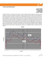
SPECTRUM ANALYZERSExternal mixerModel Frequency range Mate flange Max. input powerMA2740A 18 to 26.5 GHz MIL-F-3922/68-001KM 100 mWMA2741A 26.5 to 40 GHz MIL-F-3922/68-001AM 100 mWMA2742A 33 to 50 GHz MIL-F-3922/67B-006 100 mWMA2743A 40 to 60 GHz MIL-F-3922/67B-007 100 mWMA2744A 50 to 75 GHz MIL-F-3922/67B-008 100 mWMA2745A 60 to 90 GHz MIL-F-3922/68B-009 100 mWMA2746A 75 to 110 GHz MIL-F-3922/68B-010 100 mWOrdering informationPlease specify model/order number, name, and quantity when ordering.Model/order No.<strong>MS2667C</strong>Main frameSpectrum AnalyzerNameStandard accessoriesPower cord, 2.6 m:1 pcF0013 Fuse, 5 A: 2 pcsW1335AE MS2665C/<strong>MS2667C</strong> operation manual: 1 copyB0329G Front cover (3/4MW4U)<strong>MS2667C</strong>-02<strong>MS2667C</strong>-03<strong>MS2667C</strong>-04<strong>MS2667C</strong>-06<strong>MS2667C</strong>-07<strong>MS2667C</strong>-10<strong>MS2667C</strong>-1534AKNF50J0561J0104AJ0322BJ0911J0912OptionsNarrow resolution bandwidthNarrow resolution bandwidthHigh-speed time domain sweepTrigger/gate circuitAM/FM demodulator (outputs to loudspeaker orearphone connector)Centronics interface (GPIB interface cannot beinstalled simultaneously)Sweep signal outputApplication partsCoaxial adapter (DC to 20 GHz, SWR: 1.5, ruggedizedK-P · N-J)Coaxial cord (N-P-5W · 5D-2W · N-P-5W), 1 mCoaxial cord (BNC-P · RG-55/U · N-P) , 1 mCoaxial cord (SMA-P · SMA-P), 1 m (DC to 18 GHz,SUCOFLEX 104A)Coaxial cord (K-P · K-P), 1 m (DC to 40 GHz,SUCOFLEX 102A)Coaxial cord (K-P · K-P), 0.5 m (DC to 40 GHz,SUCOFLEX 102A)CSCJ-256K-SM 256 KB memory card (meets PCMCIA Rel. 2.0)CSCJ-512K-SM 512 KB memory card (meets PCMCIA Rel. 2.0)CSCJ-001M-SM 1024 KB memory card (meets PCMCIA Rel. 2.0)CSCJ-002M-SM 2048 KB memory card (meets PCMCIA Rel. 2.0)B0395A Rack mount kit (IEC)B0395B Rack mount kit (JIS)MP612A RF Fuse HolderMP613A Fuse ElementJ0805 DC block (Model 7003, 10 kHz to 18 GHz, ±50 V,Weinschel product, N-type)Model/order No.NameMA2507A DC Block Adapter (50 Ω, 9 kHz to 3 GHz, ±50 V, N-type)MA8601A DC Block Adapter (50 Ω, 30 kHz to 2 GHz, ±50 V,N-type)MA8601J DC Block Adapter (75 Ω, 10 kHz to 2.2 GHz, ±50 V,NC-type)MA1621A 50 Ω → 75 Ω Impedance Transformer (9 kHz to 3 GHz,±100 V, NC-type)MP614A 50 Ω ↔ 75 Ω Impedance Transformer (10 to 1200MHz, transformer type, NC-type)J0007GPIB cable, 1 mJ0008GPIB cable, 2 mJ0742ARS-232C cable, 1 m (for PC-98 Personal Computerand VP-600, D-sub 25-pins, straight)J0743ARS-232C cable, 1 m (for PC/AT compatible, D-sub9-pins, cross)J0064A 7 GHz band coaxial/waveguide adapter (5.8 to 8.6GHz, N-J · BRJ-7)J0064C 10 GHz band coaxial/waveguide adapter (8.2 to 12.4GHz, N-J · BRJ-10)J0004Coaxial adapter (N-P · SMA-J)DGM010-02000EE Coaxial cord, 2 m (N-type connector, general use)DGM024-02000EE Coaxial cord, 2 m (N-type connector, low-loss type)J0063Fixed attenuator for high power (30 dB, 10 W, DC to12.4 GHz, N-type)J0395Fixed attenuator for high power (30 dB, 30 W, DC to9 GHz, N-type)J0078Fixed attenuator for high power (20 dB, 10 W, DC to18 GHz, N-type)MP526D High Pass Filter (400 MHz band)MA1601A High Pass Filter (800/900 MHz band, N-type)MA2740A External Mixer (18 to 26.5 GHz)MA2741A External Mixer (26.5 to 40 GHz)MA2742A External Mixer (33 to 50 GHz)MA2743A External Mixer (40 to 60 GHz)MA2744A External Mixer (50 to 75 GHz)MA2745A External Mixer (60 to 90 GHz)MA2746A External Mixer (75 to 110 GHz)B0421A Carrying case (hard type, with casters)B0421B Carrying case (hard type, without casters)B0435A Carrying case (soft type)320 For product ordering information, see pages 4 – 10