

Stabilization of Vertical Cut.pdf - Plaxis
Stabilization of Vertical Cut.pdf - Plaxis
Stabilization of Vertical Cut.pdf - Plaxis

You also want an ePaper? Increase the reach of your titles
YUMPU automatically turns print PDFs into web optimized ePapers that Google loves.
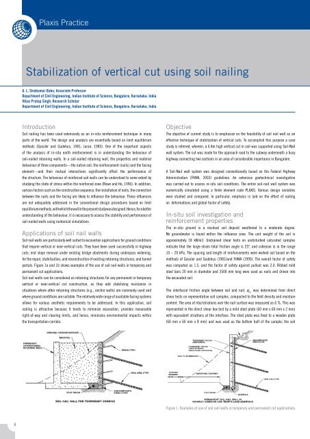
<strong>Plaxis</strong> Practice<strong>Stabilization</strong> <strong>of</strong> vertical cut using soil nailingG. L. Sivakumar Babu, Associate Pr<strong>of</strong>essorDepartment <strong>of</strong> Civil Engineering, Indian Institute <strong>of</strong> Science, Bangalore, Karnataka, IndiaVikas Pratap Singh, Research ScholarDepartment <strong>of</strong> Civil Engineering, Indian Institute <strong>of</strong> Science, Bangalore, Karnataka, IndiaIntroductionSoil nailing has been used extensively as an in-situ reinforcement technique in manyparts <strong>of</strong> the world. The design and analysis are essentially based on limit equilibriummethods (Gassler and Gudehus, 1981; Juran, 1985). One <strong>of</strong> the important aspects<strong>of</strong> the analysis <strong>of</strong> in-situ earth reinforcement is in understanding the behaviour <strong>of</strong>soil-nailed retaining walls. In a soil-nailed retaining wall, the properties and materialbehaviour <strong>of</strong> three components—the native soil, the reinforcement (nails) and the facingelement—and their mutual interactions significantly affect the performance <strong>of</strong>the structure. The behaviour <strong>of</strong> reinforced soil walls can be understood to some extent bystudying the state <strong>of</strong> stress within the reinforced zone (Rowe and Ho, 1996). In addition,various factors such as the construction sequence, the installation <strong>of</strong> nails, the connectionbetween the nails and the facing are likely to influence the behaviour. These influencesare not adequately addressed in the conventional design procedures based on limitequilibrium methods, with which the wall in the present study was designed. Hence, for a betterunderstanding <strong>of</strong> the behaviour, it is necessary to assess the stability and performance <strong>of</strong>soil-nailed walls using numerical simulations.Applications <strong>of</strong> soil nail wallsSoil nail walls are particularly well suited to excavation applications for ground conditionsthat require vertical or near-vertical cuts. They have been used successfully in highwaycuts; end slope removal under existing bridge abutments during underpass widening;for the repair, stabilization, and reconstruction <strong>of</strong> existing retaining structures; and tunnelportals. Figure 1a and 1b shows examples <strong>of</strong> the use <strong>of</strong> soil nail walls in temporary andpermanent cut applications.Soil nail walls can be considered as retaining structures for any permanent or temporaryvertical or near-vertical cut construction, as they add stabilizing resistance insituations where other retaining structures (e.g., anchor walls) are commonly used andwhere ground conditions are suitable. The relatively wide range <strong>of</strong> available facing systemsallows for various aesthetic requirements to be addressed. In this application, soilnailing is attractive because it tends to minimize excavation, provides reasonableright-<strong>of</strong>-way and clearing limits, and hence, minimizes environmental impacts withinthe transportation corridor.ObjectiveThe objective <strong>of</strong> current study is to emphasize on the feasibility <strong>of</strong> soil nail wall as aneffective technique <strong>of</strong> stabilization <strong>of</strong> vertical cuts. To accomplish this purpose a casestudy is referred, wherein, a 6.8m high vertical cut in soil was supported using Soil-Nailwall system. The cut was made for the approach road to the subway underneath a busyhighway connecting two sections in an area <strong>of</strong> considerable importance in Bangalore.A Soil-Nail wall system was designed conventionally based on the Federal HighwayAdministration (FHWA, 2003) guidelines. An extensive geotechnical investigationwas carried out to assess in-situ soil conditions. The entire soil-nail wall system wasnumerically simulated using a finite element code PLAXIS. Various design variableswere studied and compared. In particular, emphasis is laid on the effect <strong>of</strong> nailingon deformations and global factor <strong>of</strong> safety.In-situ soil investigation andreinforcement propertiesThe in-situ ground is a residual soil deposit weathered to a moderate degree.No groundwater is found within the influence zone. The unit weight <strong>of</strong> the soil isapproximately 18 kN/m3. Undrained shear tests on undisturbed saturated samplesindicate that the large-strain total friction angle is 25º, and cohesion is in the range10 – 20 kPa. The spacing and length <strong>of</strong> reinforcements were worked out based on themethods <strong>of</strong> Gassler and Gudehus (1981)and FHWA (1990). The overall factor <strong>of</strong> safetywas computed as 1.5, and the factor <strong>of</strong> safety against pullout was 2.0. Ribbed mildsteel bars 20 mm in diameter and 3500 mm long were used as nails and driven intothe excavated soil.The interfacial friction angle between soil and nail, j u, was determined from directshear tests on representative soil samples, compacted to the field density and moisturecontent. The area <strong>of</strong> ribs/striations over the nail surface was measured as 6 %. This wasrepresented in the direct shear box test by a mild steel plate (60 mm x 60 mm x 2 mm)with equivalent striations at the interface. The steel plate was fixed to a wooden plate(60 mm x 60 mm x 8 mm) and was used as the bottom half <strong>of</strong> the sample; the soilFigure 1. Examples <strong>of</strong> use <strong>of</strong> soil nail walls in temporary and permanent cut applications.
<strong>Plaxis</strong> PracticeParameterValueWall layoutHeight , H (m) 6.80Face batter, a (Degrees) 0.0Slope <strong>of</strong> backfill, β (Degrees) 0.0Soil propertiesCohesion, c (kPa) 10 - 20Friction angle, j (Degrees)5Unit weight, γ (kN/m 3 ) 18Modulus <strong>of</strong> elasticity, E S(kN/m 2 )0000Poisson’s ratio, ν 0.3Nail propertiesLength, LN (m) 3.50Diameter, D (m) 0.0Spacing, S Vx S H(m x m) 0.5 x 0.5Modulus <strong>of</strong> elasticity, E N(kN/m 2 ) x 10 8Soil-nail interface friction, j u(Degrees)5RCC facing propertiesThickness, t (m) 0.1Modulus <strong>of</strong> elasticity, E C(kN/m 2 ) x 10 7Cross-sectional area, A (m 2 /m length) 0.1Moment <strong>of</strong> inertia, I (m 4 /m length) 8.3 x 10 -5sample was compacted to the field conditions, and sliding tests were carried out underdifferent normal pressures <strong>of</strong> 25 kPa, 50 kPa and 100 kPa. The samples were shearedat a rate <strong>of</strong> 0.4mm/min, which could be considered to represent undrained conditionsin the field. Pore water pressure was not measured, and the interface parametersare expressed in terms <strong>of</strong> friction angle and cohesion. The interfacial friction anglebetween nail and soil, j u, was obtained as 25º, and cohesion was in the range10–20 kPa. The interface properties and the soil properties were nearly the same, asthe striations present on the plane surface cause the failure plane to pass throughthe soil. The properties <strong>of</strong> the native soil and the reinforcement are given in Table 1.Construction sequenceThe construction procedure consisted <strong>of</strong> excavation, nailing <strong>of</strong> the reinforcement, andconstruction <strong>of</strong> RCC facing. First, the soil was excavated to a depth <strong>of</strong> 1500 mm, andnails were driven at the desired spacing in both the horizontal and vertical directions.Nominal reinforcement for the RCC facing was provided and rigidly connected to the nailsby welding. Subsequently, a 100 mm thick RCC facing was constructed. The process wasrepeated until the desired depth <strong>of</strong> excavation was reached.Numerical simulation – using <strong>Plaxis</strong>For the numerical simulation, two-dimensional finite element code PLAXIS wasused. The Mohr-Coulomb model is used to model soil, and for nails along with facingelements an elastic model is used. Beam elements were used to model nails andFigure 2 Finite element model for the soil nailed wallfacing elements. Input parameter definitions in PLAXIS require averaging the effect <strong>of</strong>a three-dimensional problem to a two-dimensional problem. Figure 2 shows the modelledstate <strong>of</strong> the soil nailed wall.Simulation <strong>of</strong> excavation stagesAccomplishment <strong>of</strong> physical modelling, including simulation for gravity stressesusing K o-procedure, was followed with the calculation program. Simulation <strong>of</strong> the entiresoil-nail wall construction process was carried out in a sequence <strong>of</strong> construction stages.In each construction stage a sufficient number <strong>of</strong> calculation steps were used to obtainan equilibrium-state. Since the properties <strong>of</strong> the soil at the location are highly variable,the representative values <strong>of</strong> soil cohesion 10, 15 and 20 kPa were used for numericalanalysis. Also, factor <strong>of</strong> safety is determined after each construction stage using strengthreduction technique.Results and discussionsGlobal factor <strong>of</strong> safety is obtained using strength reduction technique after eachconstruction stage. Three sets <strong>of</strong> observations corresponding to cohesion value <strong>of</strong> 10 kPa,15 kPa and 20 kPa were obtained and the improvement in factor <strong>of</strong> safety is observed.Table 2 indicates the obtained factors <strong>of</strong> safety. An improvement <strong>of</strong> about 1.5 – 2.5times in values <strong>of</strong> factor <strong>of</strong> safety is observed. Also, it could be noticed that a globalfactor <strong>of</strong> safety in the range <strong>of</strong> 1.20 – 1.53 is obtained for the entire depth (6.8 m) <strong>of</strong>excavation supported using nails. This value reasonably agrees with the minimum range
<strong>Plaxis</strong> Practice<strong>Stabilization</strong> <strong>of</strong> vertical cut using soil nailingContinuationTable 2 Factors <strong>of</strong> Safety obtained using strength reduction techniqueTable 3 Horizontal displacements with excavation stages1.20 – 1.30 <strong>of</strong> recommended factor <strong>of</strong> safety for global stability, as per FHWA guidelines.Figure 3 shows the graphical representation <strong>of</strong> variation <strong>of</strong> factor <strong>of</strong> safety with the depth <strong>of</strong>excavation.FOSTable 2 Factors <strong>of</strong> Safety obtained using strength reduction techniqueAnother important aspect studied is the deformations in the soil nailed wall system.It could be noticed that a maximum horizontal deformation <strong>of</strong> 7.60 mm is observedfor the nailed wall, contrary to that <strong>of</strong> 27.25 mm for excavation <strong>of</strong> 6 m without nailing.This shows a significant reduction (about 70%) in the displacement <strong>of</strong> the vertical cut.Table 3 shows the comparison <strong>of</strong> extreme horizontal displacements for differentexcavation stages.Figure 3 Variation <strong>of</strong> factor <strong>of</strong> safety with the depth <strong>of</strong> excavationu x [mm]Figure 4 represent graphically the variation <strong>of</strong> extreme horizontal displacements withthe depth <strong>of</strong> excavation.In addition to the stability and deformations aspect <strong>of</strong> soil-nail wall system, variousdesign parameters with regard to development <strong>of</strong> axial forces, shear forces,moments and deformations in individual nail and facing elements were also taken intoaccount. Some <strong>of</strong> these results are as shown in Figure 5 to 8 and are summarized inTable 4. Earth pressure distribution behind the nailed wall is as shown in Figure 9. Amaximum value <strong>of</strong> 96 kN/m 2 passive earth pressure is obtained. The trend <strong>of</strong> variation <strong>of</strong>forces and moments are found to conform to theoretical expectations. It also justifies theeffectivene <strong>of</strong> numerical simulations.Figure 4 Variation <strong>of</strong> horizontal displacement <strong>of</strong> vertical cut with depth <strong>of</strong> excavationu x [mm]Figure 5 Variation <strong>of</strong> maximum horizontal displacement <strong>of</strong> nails with depth
<strong>Plaxis</strong> PracticeN[kN/M]Figure 6 Variation <strong>of</strong> maximum axial force in nails with depthTable 4 Summary <strong>of</strong> design parameters for nails and facing elementFigure 7 Pattern <strong>of</strong> variation <strong>of</strong> axial force along nail length (alternate nail from top shown)Concluding remarksThe results provide an understanding <strong>of</strong> the effect <strong>of</strong> soil-nailing on the globalstability <strong>of</strong> vertical cuts using numerical simulations. The results and analysisindicate that the soil-nailed wall is stable with respect to both stability and deformationconsiderations. Further, it could be concluded that soil nailing is a viable andeconomical option for supporting vertical cuts particularly in locations wheresite-constraints are more predominant and project duration is very limited.AcknowledgementsThe work presented in this article is a part <strong>of</strong> the research project Guidelines for SoilNailing Technique in Highway Engineering (R-86) financed by the Ministry <strong>of</strong> Shipping,Road Transport and Highways, Government <strong>of</strong> India, New Delhi. The authors expressthanks to the Ministry for funding and providing necessary support for the project.Figure 8 Variations <strong>of</strong> axial forces, bending moments and shear forces in facing elementsReferences- Dawson E. M., Roth W. H. A. and Drescher A. (1999) Slope stability analysis by strengthreduction. Geotechnique, 49, No. 6, 835–840.- FHWA (2003) Carlos A. Lazarte, Victor Elias,- R. David Espinoza, Paul J. Sabatini, Geotechnical engineering circular No. 7, Soil Nail -Walls, 0-IF-03-017.- Matsui, T. and San, K-C. (1992) Finite element slope stability analysis by shear strengthreduction technique, Soils and Foundations, Vol. 32, No. 1, pp. 59-70.- PLAXIS (2006) Reference Manual, PLAXIS B.V., The Netherlands.- Babu, G. L. S., Murthy, B. R. S. and Srinivas, A. (2002): “Analysis <strong>of</strong> construction factorsinfluencing the behavior <strong>of</strong> soil nailed earth retaining walls”, Ground Improvement, 6,No. 3, pp. 137 – 143.Figure 9 Variation <strong>of</strong> earth pressures behind the soil nail wall


