Aggregate Control Unit GENCON II pro - DSL electronic ® GmbH
Aggregate Control Unit GENCON II pro - DSL electronic ® GmbH
Aggregate Control Unit GENCON II pro - DSL electronic ® GmbH

Create successful ePaper yourself
Turn your PDF publications into a flip-book with our unique Google optimized e-Paper software.
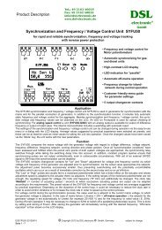
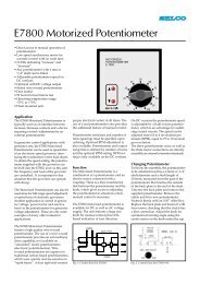
IOB1<br />
CONTROL CUBICLE<br />
BAT -<br />
#1<br />
<strong>GENCON</strong> <strong>II</strong><br />
PICK-UP<br />
ANALOG OUT<br />
C12 BAT -<br />
#1 THIS CONNECTION MAKES THE METALLIC CUBICLE<br />
A SHIELD AGAINST CAPACITIVELY COUPLED NOISE<br />
GOVERNOR<br />
BAT -<br />
MAGNETIC PICK-UP<br />
#3 CABLE SHIELDS SHOULD BE CONNECTED AT ONE SIDE ONLY<br />
#2 THE CONTROL CUBICLE GROUND IS<br />
THE GOVERNOR BAT- TERMINAL<br />
�<br />
- +<br />
NOISE VOLTAGE ACROSS THIS WIRE<br />
GEN-SET<br />
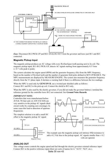
Easy: Disconnect B12 PICK-UP and B22 ANALOG OUT from the governor and leave just B11 and B21<br />
connected.<br />
Magnetic Pickup Input<br />
The magnetic pickup <strong>pro</strong>duces an AC voltage with every flywheel/gear tooth passing next to its coil. The<br />
magnetic pickup input, B11-B12 PICK-UP, detects AC signals starting from ap<strong>pro</strong>ximately 0.5 Vrms<br />
(± 0.7 volts peak to peak).<br />
The system calculates the engine speed (RPM) and the generator frequency (Hz) from the MPU frequency,<br />
based on the number of flywheel teeth and the number of generator field poles defined in SET-UP/BASICS. The<br />
MPU measurements are displayed by MEASURE\ENGINE. The system also measures the generator frequency<br />
directly from the V1 phase input. It declares a warning fault if there is a difference between the two readings.<br />
When the MPU is used only by <strong>GENCON</strong> <strong>II</strong>, use a twisted pair shielded cable as follows:<br />
Connect B11 and B12 to the pick-up coil. Connect the shield to B13 only.<br />
When the MPU is also used by the electric governor, if you did not make the governor battery(-) terminal the<br />
reference ground for the controller leave B12 not connected. See Ground Noise Hazards.<br />
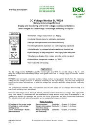
IMPORTANT NOTE:<br />
<strong>Control</strong>lers that were manufactured before<br />
20 Feb. 94 (last unit s/n A50 4 02 028) are<br />
very sensitive to the pickup AC signals (their<br />
circuit works by counting zero crossings). In<br />
some cases this lead to detection of spurious<br />
frequencies.<br />
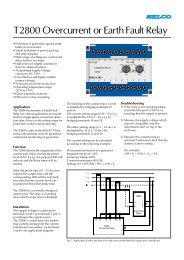
The simplest solution is to add a small DC<br />
offset to the magnetic pickup AC signal:<br />
B11 MPU+<br />
B12 MPU-<br />
+24V BAT<br />
10K ohm<br />
Typical<br />
Magnetic Pickup<br />
Resistance<br />
85 ohm<br />
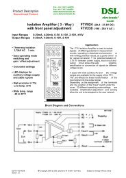
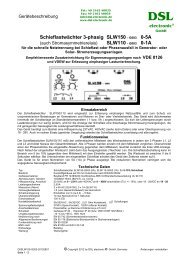
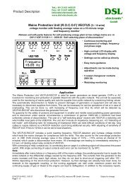
NOISE SIGNAL<br />
NOISE SIGNAL<br />
The example uses the magnetic pickup coil intrinsic 85Ω resistance to<br />
add a 0.2 Vdc bias to the pickup signal. AC signals smaller than ± 0.2<br />
volts are ignored.<br />
ANALOG OUT<br />
This voltage source controls the engine speed and fuel through the electric governor external reference input:<br />
Connect B21 to the positive reference input (there are sorts of names for it: "AUX", "ILS", etc.).<br />
Seite 30 von 43<br />
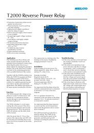
�<br />
�<br />
NOISE SIGNAL<br />
AFTER ZERO CROSSING DETECTION<br />
NOISE SIGNAL<br />
AFTER ZERO CROSSING DETECTION