International Series GFX Inverter/Charger - OutBack Power Systems
International Series GFX Inverter/Charger - OutBack Power Systems
International Series GFX Inverter/Charger - OutBack Power Systems

Create successful ePaper yourself
Turn your PDF publications into a flip-book with our unique Google optimized e-Paper software.
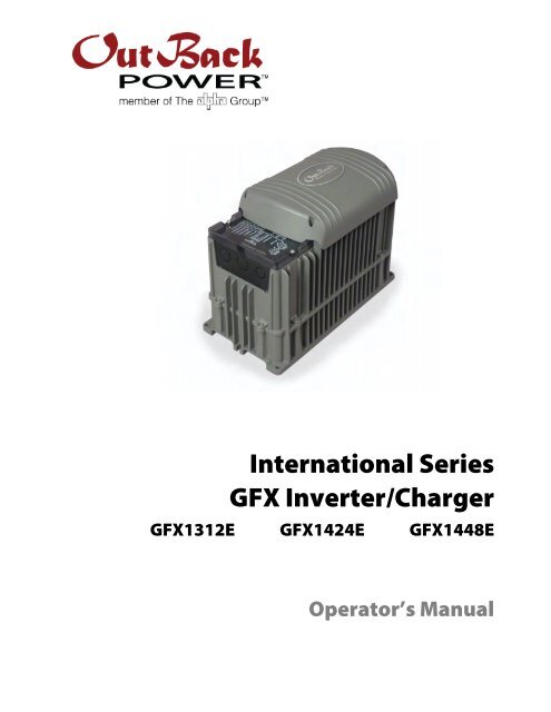
<strong>International</strong> <strong>Series</strong><strong>GFX</strong> <strong>Inverter</strong>/<strong>Charger</strong><strong>GFX</strong>1312E <strong>GFX</strong>1424E <strong>GFX</strong>1448EOperator’s Manual
About <strong>OutBack</strong> <strong>Power</strong> Technologies<strong>OutBack</strong> <strong>Power</strong> Technologies is a leader in advanced energy conversion technology. Our productsinclude true sine wave inverter/chargers, maximum power point tracking charge controllers, andsystem communication components, as well as circuit breakers, batteries, accessories, andassembled systems.Contact InformationTelephone: +1.360.435.6030+1.360.618.4363 (Technical Support)+1.360.435.6019 (Fax)Address:North America5917 – 195 th Street N.E., #7Arlington, WA 98223 USAAddress:Sales, Marketing, & Warranty6115 – 192nd Street NEArlington, WA 98223 USAE-mail:Support@outbackpower.comWeb Site:www.outbackpower.comDisclaimerUNLESS SPECIFICALLY AGREED TO IN WRITING, OUTBACK POWER TECHNOLOGIES(a) MAKES NO WARRANTY AS TO THE ACCURACY, SUFFICIENCY OR SUITABILITY OF ANY TECHNICALOR OTHER INFORMATION PROVIDED IN ITS MANUALS OR OTHER DOCUMENTATION.(b) ASSUMES NO RESPONSIBILITY OR LIABILITY FOR LOSS OR DAMAGE, WHETHER DIRECT, INDIRECT,CONSEQUENTIAL OR INCIDENTAL, WHICH MIGHT ARISE OUT OF THE USE OF SUCH INFORMATION. THEUSE OF ANY SUCH INFORMATION WILL BE ENTIRELY AT THE USER’S RISK.Warranty Summary<strong>OutBack</strong> <strong>Power</strong> Technologies warrants that the products it manufactures will be free from defects inmaterials and workmanship for a period of five (5) years subject to the conditions set forth in thewarranty detail, found on page 55 of this manual.<strong>OutBack</strong> <strong>Power</strong> Technologies cannot be responsible for system failure, damages, or injury resultingfrom improper installation of their products.Notice of Copyright<strong>International</strong> <strong>Series</strong> <strong>GFX</strong> Operator’s Manual © February 2012 by <strong>OutBack</strong> <strong>Power</strong> Technologies.All Rights Reserved.Trademarks<strong>OutBack</strong> <strong>Power</strong> is a registered trademark of <strong>OutBack</strong> <strong>Power</strong> Technologies.Date and RevisionFebruary 2012, Revision BPart Number900-0112-01-00 Rev B (for firmware revision 002.094.xxx)
Important Safety InstructionsREAD AND SAVE THESE INSTRUCTIONS!This manual contains important safety instructions for the <strong>International</strong> <strong>Series</strong> <strong>GFX</strong> inverters. Read allinstructions and cautionary markings on the inverter and on any accessories or additional equipmentincluded in the installation. Failure to follow these instructions could result in severe shock or possibleelectrocution. Use extreme caution at all times to prevent accidents.AudienceThis manual is intended for anyone required to operate the <strong>GFX</strong> inverter. Operators must be familiarwith all the safety regulations pertaining to operating this kind of equipment as dictated by local code.Operators must also have a complete understanding of this equipment’s features and functions. Donot use this product unless it has been installed by a qualified installer in accordance with the<strong>International</strong> <strong>Series</strong> <strong>GFX</strong> Installation Manual.Symbols UsedWARNING: Hazard to Human LifeThis type of notation indicates that the hazard could be harmful to human life.CAUTION: Hazard to EquipmentThis type of notation indicates that the hazard may cause damage to the equipment.IMPORTANT:This type of notation indicates that the information provided is important tothe installation, operation and/or maintenance of the equipment. Failure tofollow the recommendations in such a notation could result in voiding theequipment warranty.General SafetyWARNING: Limitations on UseThis equipment is NOT intended for use with life support equipment or other medicalequipment or devices.CAUTION: Equipment DamageOnly use components or accessories recommended or sold by <strong>OutBack</strong> <strong>Power</strong>Technologies or its authorized agents.900-0112-01-00 Rev B 1
Table of ContentsList of TablesTable 1 Terms and Definitions..................................................................................................................... 2Table 2 Battery LED Values..........................................................................................................................11Table 3 Status LED Quick Reference ........................................................................................................12Table 4 Basic Troubleshooting Steps ......................................................................................................31Table 5 Error Troubleshooting...................................................................................................................37Table 6 Warning Troubleshooting............................................................................................................38Table 7 Disconnect Troubleshooting ......................................................................................................39Table 8 Stop Sell (and Charge) Reasons .................................................................................................40Table 9 Electrical Specifications (<strong>GFX</strong>1312E)........................................................................................43Table 10 Mechanical Specifications (<strong>GFX</strong>1312E)...................................................................................43Table 11 Electrical Specifications (<strong>GFX</strong>1424E)........................................................................................44Table 12 Mechanical Specifications (<strong>GFX</strong>1424E)...................................................................................44Table 13 Electrical Specifications (<strong>GFX</strong>1448E)........................................................................................45Table 14 Mechanical Specifications (<strong>GFX</strong>1448E)...................................................................................45Table 15 Environmental Specifications for All Models........................................................................46Table 16 Interconnection Response to Voltage and Frequency .....................................................46Table 17 12-Volt <strong>Inverter</strong> Settings (MATE) ...............................................................................................47Table 18 24-Volt <strong>Inverter</strong> Settings (MATE) ...............................................................................................48Table 19 48-Volt <strong>Inverter</strong> Settings (MATE) ...............................................................................................49Table 20 12-Volt <strong>Inverter</strong> Settings (MATE3).............................................................................................50Table 21 24-Volt <strong>Inverter</strong> Settings (MATE3).............................................................................................51Table 22 48-Volt <strong>Inverter</strong> Settings (MATE3).............................................................................................52List of FiguresFigure 1 <strong>International</strong> <strong>Series</strong> <strong>GFX</strong> <strong>Inverter</strong>/<strong>Charger</strong> .............................................................................. 7Figure 2 MATE3 and MATE System Display and Controller................................................................ 8Figure 3 AC Wiring Compartment................................................................................................................ 9Figure 4 LED Indicators...................................................................................................................................11Figure 5 Charging Stages Over Time.........................................................................................................18Figure 6 Repeated Charging Cycles...........................................................................................................21Figure 7 <strong>OutBack</strong> HUB4 and MATE.............................................................................................................25Figure 8 Example of Parallel Stacking Arrangement (Three <strong>Inverter</strong>s) ........................................26Figure 9 Example of Three-Phase Stacking Arrangement (Three <strong>Inverter</strong>s) ..............................26900-0112-01-00 Rev B 5
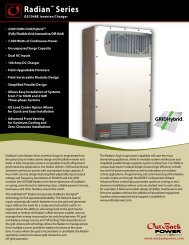
Welcome to <strong>OutBack</strong> <strong>Power</strong> TechnologiesIntroductionThank you for purchasing the <strong>OutBack</strong> <strong>International</strong> <strong>Series</strong> <strong>GFX</strong> <strong>Inverter</strong>/<strong>Charger</strong>. This product offers acomplete power conversion system between batteries and AC power. It can provide backup power orcomplete off-grid service.‣ Battery-to-AC inverting which delivers 230 Vac at 50 Hz‣ AC-to-battery charging‣ Rapid transfer between AC source and inverter output with minimal delay time‣ <strong>Inverter</strong> load support for a small AC source‣ 12-, 24-, and 48-volt inverters‣ Wattages from 1.3 kVA to 1.4 kVA‣ Stackable in parallel and three-phase configurations‣ Uses energy from PV, wind, and other renewable resources. Use of <strong>OutBack</strong> FLEXmax charge controllers willoptimize power production from PV sources.‣ Grid-interactive capable‣ CE compliant for off-grid use2 pt./ flat headFigure 1<strong>International</strong> <strong>Series</strong> <strong>GFX</strong> <strong>Inverter</strong>/<strong>Charger</strong>900-0112-01-00 Rev B 7
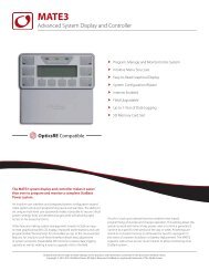
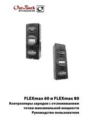
IntroductionSystem Display and ControllerThe <strong>GFX</strong> inverters have no external controls. They can operate normally without an external control orinterface. Basic modes and settings are pre-programmed at the factory. (See page 47 for defaultsettings.)The MATE and MATE2 System Display and Controller (sold separately) are <strong>OutBack</strong> products designedto accommodate programming and monitoring of an <strong>OutBack</strong> power system.The MATE3 System Display and Controller (also sold separately) is an advanced system display thatcan interface with the <strong>GFX</strong> inverter. It has a simpler user interface and more options than the MATE orMATE2. It also has data logging and Web interface functions.Each system display provides the means to adjust the factory default settings to correctly match theinstallation where needed. It also provides the means to monitor system performance andtroubleshoot fault or shutdown conditions.Once settings are modified, the system display can be removed from the installation. The settings arestored in the nonvolatile memory of the <strong>GFX</strong> inverter. However, it is highly recommended to include asystem display as part of the system. This provides the means to monitor system performance andrespond quickly should it be necessary to correct a fault or shutdown condition.The MATE3’s Configuration Wizard is capable of automatically configuring inverters to a series ofpreset values. This is often more efficient than attempting to manually program each setting in eachinverter. Affected fields include system type, battery charging, and AC source configuration. (Formore information, see the MATE3 Owner’s Manual).IMPORTANT:Some functions are not based in the inverter, but are part of the systemdisplay’s firmware. They will not function if the system display is removed.These functions are listed on page 30. For a detailed description of functionsand programming, please see the manual for the system display.MATE3MATEFigure 2MATE3 and MATE System Display and Controller8 900-0112-01-00 Rev B
Functional TestPre-startup ProceduresCommissioning1. Ensure all DC and AC overcurrent devices are opened or turned off.2. Double-check all wiring connections.3. Inspect the work area to ensure tools or debris have not been left inside.4. Verify battery voltage using a digital voltmeter (DVM). Confirm the voltage is correct for theinverter model. Confirm the polarity.5. Connect the system display (if present).CAUTION: Equipment DamageIncorrect battery polarity will damage the inverter. Excessive battery voltage also may damagethe inverter. This damage is not covered by the warranty.StartupIf steps are inapplicable, they can be omitted. However, it is highlyrecommended that all applicable steps be performed as below.If the results of a step do not match the description, see theTroubleshooting section on page 31.To start the system:1. Close the main DC circuit breaker (or connect the fuse) from thebattery bank to the inverter. Repeat for every inverter present.2. Observe the LEDs in the AC wiring compartment. One of thethree BATTERY LEDs should be illuminated — green, yellow, orred. Any of them are acceptable at this stage. (See page 11 fora description of the LEDs.) The INVERTER LED (green) maycome on at this time. The fan will run briefly and the relay willclick as a self-test.3. The ERROR LED may flash briefly. If it remains illuminated orcontinues to flash during any step, proceed immediately topage 31 for troubleshooting.4. Confirm that the system display is operational. (See the systemdisplay manual for a description of the menu items that appearon a correctly functioning display.)Continued on the next page...Figure 3AC Wiring Compartment900-0112-01-00 Rev B 9
Commissioningcontinued from previous page....5. If the INVERTER LED (green) is not illuminated, turn on the inverter using the system display orexternal switch.6. Check the STATUS LEDs. Confirm that the INVERTER LED (green) is illuminated.7. Using a DVM, verify 230 Vac between the AC HOT OUT and AC NEUTRAL OUT terminals. Do notturn on any AC circuit breakers at this time.8. Using the system display, perform all programming for stacking, battery charging, AC current,generator starting, and any other functions. Refer to the Description of Functions sectionbeginning on page 13. Also refer to the system display manual and any other literature as needed.After programming is completed, perform the following steps:1. If other inverters are on the system, use a DVM to verify correct voltage from AC HOT OUT on oneinverter to the next. Parallel-stacked inverters should collectively read 0 Vac (although individuallythey should still read 230 Vac). Three-phase inverters should collectively read 400 Vac.2. Close the AC output circuit breakers. If AC Bypass circuit breakers are present, place them in thenormal (non-Bypass) position. Do not connect an AC input source or close any AC input circuits.3. Use a DVM to verify correct voltage at the AC load panel.4. Connect a small AC load and test for proper functionality.5. Close the AC input circuit breakers and connect an AC source.6. Check the STATUS LEDs. The AC IN LED (yellow) should flash. The INVERTER LED will remainilluminated for a short time. When the AC IN LED stays illuminated, the INVERTER LED should godark. This means the inverter is no longer drawing on batteries, but is using the AC source.7. If the battery charger has been enabled, confirm that it is charging by using the system display.The inverter will perform a full battery charge when first powered up. This may take several hours.If restarted after a temporary shutdown, the inverter may skip most or all of the charging cycle.8. Test any other functions which have been enabled, such as generator start, selling, orsearch mode. <strong>International</strong> <strong>Series</strong> <strong>GFX</strong> inverters have a minimum one-minute delay before sellingwill begin.9. Compare the DVM’s readings with the system display meter readings. If necessary, the systemdisplay’s readings can be calibrated to match the DVM more accurately. AC input voltage, ACoutput voltage, and battery voltage can be calibrated.<strong>Power</strong>ing DownIf steps are inapplicable, they can be omitted. However, it is highly recommended that all applicablesteps be performed in the following order.To <strong>Power</strong> Down the System:1. Turn off all load circuits and AC input sources.2. Turn off all renewable energy circuits.3. Turn each inverter OFF using the system display or external switch.4. Turn off the main DC overcurrent device for each inverter.Adding New DevicesWhen adding new devices to the system, first power down the system according to the precedinginstructions. After adding new devices, perform another functional test, including programming.10 900-0112-01-00 Rev B
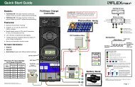
LED IndicatorsOperationAUX LED(see page 27)BATTERY LEDsSTATUS LEDsFigure 4LED IndicatorsBATTERY LEDSThe battery LEDs show the approximate battery state. (See IMPORTANT note below.) The BATTERYLEDs are independent of STATUS LEDs. Any STATUS LED could accompany any BATTERY LED basedon certain conditions. Common combinations are noted.‣ A GREEN LED means the batteries have an adequate charge at that time. It does not always mean they arefull. May be accompanied by a YELLOW STATUS LED when an AC source is charging.‣ A YELLOW LED means the batteries are somewhat discharged.‣ A RED LED means the batteries are greatly discharged and may require attention. May be accompanied by aRED STATUS LED to indicate a Low Battery ERROR.Table 2 Battery LED ValuesColor 12 Vdc Unit 24 Vdc Unit, ± 0.2 Vdc 48 Vdc Unit, ± 0.4 Vdc Battery StatusGREEN 12.5 Vdc or higher 25.0 Vdc or higher 50.0 Vdc or higher ACCEPTABLEYELLOW 11.5 to 12.4 Vdc 23.0 to 24.8 Vdc 46.0 to 49.6 Vdc MARGINALRED 11.4 Vdc or lower 22.8 Vdc or lower 45.6 Vdc or lower LOWNOTES:‣ Gaps in the table (higher-voltage units) are due to the resolution of the inverter’s DC meter.‣ These voltage settings are not the same as the Low Battery Cut-Out (LBCO) set point. (See pages 13 and 37.)The Battery LED settings cannot be changed.‣ Voltages higher than shown in the GREEN row usually means that the batteries are charging.IMPORTANT:Battery voltage does not always indicate an accurate state of charge. It is accurate if batteries have beenat rest for several hours at room temperature (25°C or 77°F, or as specified by the battery manufacturer).If they have any loads, a charging source, or are at another temperature, their voltage may not reflecttheir true state. The <strong>OutBack</strong> FLEXnet DC is a battery monitor which can provide accurate measurements.900-0112-01-00 Rev B 11
OperationSTATUS LEDSGREEN‣ Solid: The inverter is ON and providing power. If accompanied by solid yellow LED, unit is selling power tothe utility grid. (See page 24 for a description of the Sell function.)‣ Flashing: The inverter has been turned ON but is idle. May be accompanied by the yellow LED. If notaccompanied by the yellow LED, the unit is in inverting mode and is idle due to lack of demand. This can bebecause the unit is in Search mode. (See page 14 for a description of Search.)‣ Off: Unit is OFF. It is not waiting to provide power. Any power present is from another source such as theutility grid or generator. (See Startup on page 9, or the system display manual, to turn the unit ON.) The unitmay also be a slave that is in <strong>Power</strong> Save mode. If so, the master inverter may still be providing power to thesystem. (See page 27 for a description of <strong>Power</strong> Save.)YELLOW‣ Solid: The AC source is connected and providing power. Unit may or may not be charging the batteries,depending on settings. May be accompanied by green LED.‣ Flashing: The AC source is present but has not been accepted. If flashing continues, the unit is refusing thesource. This can occur for the following reasons.∼ The AC source may have quality issues. External diagnosis may be required. (See page 15 for adescription of input criteria. See the system display manual for diagnosis using the meter displays.)∼ In the system display, the AC Input menu is set to DROP. (See the system display manual for adescription of the AC IN or AC INPUT hot key.)∼ In the system display, the High Battery Transfer (HBX) feature or the Grid Use feature intentionallydisconnected the inverter. (See the system display manual for a description of these modes.)‣ Off: No AC source is detected. If a source is supposed to be present, confirm the voltage between AC HOT INand AC NEUTRAL IN terminals.RED‣ Solid: ERROR. Unit has shut down due to a critical problem which may be internal or external to the inverter.This LED is accompanied by an error message in the system display. See page 37 for a description oferror messages.‣ Flashing: WARNING. Unit has detected a non-critical problem but has not yet shut down. A warning doesnot always lead to a shutdown — if it does, it becomes an error. This LED is accompanied by a warningmessage in the system display. See page 37 for a description of warning messages.‣ Off: No problems are detected.Table 3Status LED Quick ReferenceColor State <strong>Inverter</strong> State NotesSolid GREEN <strong>Inverter</strong> is ON and providing power. If accompanied by YELLOW LED, unit is selling.GREENFlashing GREEN <strong>Inverter</strong> is ON but standing by. Unit may be in Search mode.Off <strong>Inverter</strong> is not providing power. Unit is either OFF or has been replaced by anAC source (see next item).Solid YELLOW AC source connected and providingpower.Unit may or may not be charging batteries,depending on settings.YELLOW Flashing YELLOW AC source present but not yet accepted. Unit may be programmed not to accept thesource, or the source may have quality issues.Off No AC source is detected. If source is present, check AC input.Solid REDERROR. Unit has shut down. SeeTroubleshooting.To see error messages, see the system displaymanual.REDFlashing REDOffWARNING. Unit detected a problem buthas not yet shut down. SeeTroubleshooting.No problems detected.To see warning messages, see the systemdisplay manual.12 900-0112-01-00 Rev B
Description of FunctionsOperationAll items identified as settable or adjustable have set points which can be accessed using the remotesystem display. (See the system display manual for instructions on locating these set points.) Thedefault settings and ranges of adjustment are listed near the end of this book, beginning on page 47.Each function is accompanied by a symbol representing the inverter and that function:DCThese items represent the input from the ACTRANSFERsource, the output to the AC loads, DC functions(inverting, charging, etc), and the transfer relay.AC INAC OUTArrows on each symbol represent current flow.The symbols for each function may have other features depending on the function.InvertingA <strong>GFX</strong> inverter uses a transformer and a high-frequency H-Bridge FET design to convert DC voltagefrom batteries into AC voltage that is usable by AC appliances. It will continue to do this as long as thebatteries have sufficient energy. The batteries can be supplied or recharged from other sources, suchas solar, wind, or hydroelectric power.The inverter requires batteries to operate. Other sources may not maintain DC voltages that areconsistent enough for the inverter to operate reliably.CAUTION: Equipment DamageDo not substitute other DC sources in place of the batteries. High or irregular voltagesmay damage the inverter. It is normal to use other DC sources in conjunction with thebatteries and the inverter, but not in place of the batteries.Certain features will affect the inverter’s operation. These features only operate when the inverter isgenerating AC power on its own. They do not function when the inverter is supplied by an AC source.‣ Low Battery Cut-Out (LBCO): This function prevents the inverter from draining the batteries completely.When the DC voltage drops below a specified level for 5 minutes, the inverter will stop functioning. Thesystem display will give a Low Battery Voltage or Low Battery V error. This is one of the Error messagesdescribed on page 37. This function is intended to protect both the batteries and the inverter’s output.(Continuing to invert on a low DC voltage may produce a distorted waveform.) This item is adjustable.‣ Low Battery Cut-In (LBCI): The recovery point from Low Battery Cut-Out. When the voltage rises above thispoint for 10 minutes, the Low Battery error will clear and the inverter will function again. This is adjustable.∼ Connecting an AC source to charge the batteries will also clear a Low Battery error.‣ AC Output Voltage: The inverter’s AC output can be turned up or down by a certain amount to adjust forconditions. This item is adjustable.‣ The inverter is also controlled by a high battery cut-out function. If the DC voltage rises above a certain level,the inverter will immediately stop functioning. The system display will give a High Battery Voltage or HighBattery V error. This is one of the Error messages displayed on page 37. (If the voltage drops below thispoint, the inverter automatically recovers.)∼ For a 12-volt inverter, this voltage is 17 volts.∼ For a 24-volt inverter, the voltage is 34 volts∼ For a 48-volt inverter, the voltage is 68 volts.The high battery cut-out voltages cannot be changed.This function is intended to protect theinverter’s output and loads. Continuing toinvert on a high DC voltage may produce adistorted waveform. Note that the high batterycut-out does not alleviate the high batterycondition itself; it is an external condition.900-0112-01-00 Rev B 13
OperationSearchAn automated search circuit is available to minimize the power draw when no loads are present.When enabled, the inverter does not always deliver full output. The output is reduced to brief pulseswith a delay between them. These pulses are sent down the output lines to see if a resistance ispresent. In effect, the pulses “search” for a load. If one is detected, the inverter’s output increases tofull voltage so that it can power the load. When the load is turned off, the inverter “goes to sleep” andbegins searching again.The sensitivity of Search mode is in increments of approximately 0.1 Aac. The default is 6 increments,or 0.6 Aac. A load which draws this amount or greater will “wake up” the inverter.NOTE: Due to changing load characteristics, these increments are only approximate and may notfunction exactly as listed.The pulse duration and the delay both have a time period that is measured in AC cycles. These twoitems and the load detection threshold are adjustable.‣ Search mode can save a considerable amount of power, particularly in smaller systems with intermittent use.‣ Search mode may not be useful in larger systems with loads that require continuous power (e.g., clocks,answering machines, fax machines). Search mode may cause nuisance shutdowns, or it may sleep so rarelythat there is no benefit.‣ Some devices may not be easily detectable by Search mode.InputWhen the <strong>GFX</strong> inverter input terminals are connected to a stable AC source, the inverter willsynchronize itself with that source and use it as the primary source of AC power. (See “AC SourceAcceptance” on page 15.) In this situation, the transfer relay will engage, linking the AC source directlywith the inverter’s output. It can also use the source to charge batteries. (See “Transfer” on page 16and “Battery Charging” on page 18.)‣ Two sets of input criteria are available, one for the utility grid and one for a generator. Only one source canbe selected at a time. In the MATE system display, the source is selected using the ac transfer control menu.In the MATE3 system display, it is selected using either the <strong>Inverter</strong> Input Select or the AC Input and CurrentLimit menus. See the system display manual for more information. (For other aspects of input selection, seethe items below. Also see AC Current Settings on page 15.) Both grid and generator criteria are adjustable.‣ The grid-interactive function can sell power using the input connection. (See the section entitled “Selling” onpage 24.) In the MATE, this function only operates if grid is selected in the ac transfer control menu. It doesnot function if gen is selected.‣ The Input Support feature can use battery power to assist a smaller AC source. (See the section entitled“Input Support” on page 17.)‣ There are a number of considerations when selecting the type and size of an AC generator. (See the sectionentitled “Generators” on page 16.)‣ The AC input current is used to power both loads and battery charging. The total should not exceed the sizeof the AC overcurrent device or AC source. These devices should be sized appropriately during planning.‣ The loads powered by the inverter must not exceed the size of the inverter’s transfer relay. (See the sectionentitled “Transfer” on page 16.)CAUTION: Equipment DamageCurrent draw in excess of the inverter’s transfer relay rating can damage the transferrelay. This damage is not covered by warranty.14 900-0112-01-00 Rev B
OperationAC Current SettingsThe AC current settings control the amount of current that the inverter draws from the source(s). Theamount of current is controlled by the grid or generator limit settings. These settings should beadjusted to match the size of the input circuit breaker or input conductor. In the system display, if thesource is set to grid, the inverter uses the grid settings. If the source is set to gen, the inverter uses thegenerator settings.‣ This is intended to protect a generator or source that may not be large enough to supply enough current forboth charging and loads. If the combined charging and loads exceed this setting, the inverter will reduce itscharge rate and give priority to the loads. If the loads exceed this number on their own, the charge rate willbe reduced to zero. The inverter is capable of supporting the source with power from the batteries. See thesection entitled “Input Support” on page 17.‣ If multiple parallel inverters are installed with an AC source of limited amperage, the total combinedamperage settings for all units must be less than the AC input circuit. The Configuration Wizard in theMATE3 can perform this calculation. However, the inverters do not perform this calculation. If the MATE3 orthe Configuration Wizard are not used, it may be necessary to divide the input size by the number ofinverters and assign an equal part of the amperage to each port.AC Source AcceptanceThe input source must meet the following specifications to be accepted:‣ 230 Vac, ± 22 Vac (default setting), and‣ 50 Hz, ± 5 HzWhen these conditions are met, the inverter will close its transfer relay and accept the input source.This occurs after a delay which is specified below. If the conditions are not met, the inverter will notaccept the source. If it was previously accepted and then rejected, the inverter will open the relay andreturn to inverting power from the batteries.‣ If the source is set to grid, there is a connection delay of approximately 15 seconds. This time is notadjustable.‣ If the source is set to gen, there is a connection delay with a default setting of 0.5 minutes. This is intended asa generator warmup period. This item is adjustable.NOTES:Several items, external to the inverter, may prevent the inverter from accepting AC power even ifelectrical conditions are met. One is the high-battery transfer (HBX) mode, which is operated by thesystem display. (See page 30 and the system display manual.) Another is the system display’s AC INor AC INPUT hot key, which can turn off the input to all inverters. (See the system display manual.)The inverter has additional criteria that control whether it sells power. The inverter may accept ACpower but refuse to sell if the acceptance criteria are met, but the grid-interactive criteria are not. (Seethe section entitled “Selling” on page 24.)900-0112-01-00 Rev B 15
OperationGeneratorsA generator should be sized to provide enough power for both loads and battery charging.‣ The generator needs a single circuit which is sized to provide current to all inverters on a given phase or leg.‣ It is usually recommended that the generator be sized at twice the wattage of the inverter system. Manygenerators may not be able to maintain AC voltage or frequency for long periods of time if they are loadedmore than 80% of rated capacity.‣ Using the MATE system display, it is recommended to set the AC source to gen when connecting a generator.If the setting is left on grid, the inverter’s internal settings will still be set for utility-grade power. Unless thegenerator delivers extremely high-quality power, it might not be accepted. (Alternately, the inverter mightaccept the generator and attempt to sell power back to it.) Changing to gen will remove the requirementsfor high-grade power and will prevent selling.The generator is required to have a stable output before its power is accepted by the inverter. Somegenerators with less stable or uneven outputs may not be accepted.When using capacitor-excited generators or self-excited induction generators, there can be sideeffects while using the Input Support feature (see page 17). These generators do not always deliverfull output when operating in parallel with another source of power, such as the Input Supportfeature. The inverter’s battery charger may work erratically or at a low charge rate. It may benecessary to disable the Input Support feature. Consult the generator manufacturer if necessary.TransferThe inverter uses a transfer relay to alternate between the states of inverting and of accepting an ACsource. Until the relay energizes, the AC HOT IN and AC HOT OUT terminals are electrically isolatedfrom each other; when it closes, they become electrically common. When the relay changes states,the physical transfer delay is approximately 12 milliseconds.‣ The AC NEUTRAL IN and AC NEUTRAL OUT terminals are electrically common regardless of the state ofthe relay.‣ The relay contacts are limited to 30 amps per phase or leg. The continuous loads on that output shouldnever exceed this number. When connected to an AC source, the inverter cannot limit the load current. Anoverload condition is possible.CAUTION: Equipment DamageCurrent draw in excess of the inverter’s transfer relay rating can damage the transferrelay. This damage is not covered by warranty.The inverter does not filter or clean up the power from the AC source. The voltage and power qualityreceived by the output loads is the same as that of the source. If the voltage or quality do not meetthe inverter’s input limits (see page 15), it will disconnect and return to the inverting mode.‣ If the AC source meets the inverter’s requirements but is irregular, any fluctuations will be transferred to theloads. If the loads are sensitive, it may be necessary to improve the quality of the AC source.‣ For a smoother transition, it may be useful to raise the inverter’s lower acceptance limit. The default settingis 208 Vac. A higher setting will cause the inverter to transfer sooner in the event of a quality problem.In a stacked system, slaves are ordered to transfer at the same time as the master. If a slave does notsense an AC source, it will suffer a Phase Loss Error (see page 37). The slave will continue inverting.16 900-0112-01-00 Rev B
OperationInput SupportA system display is required to control this function. When this function is enabled, the inverter limitsthe current draw from an AC source, augmenting it with additional current from the batteries whennecessary. This helps prevent overloading a small AC circuit or generator during short-term use.Initially the AC source current is used for both loads and battery charging. In the MATE system display,the ac1/grid limit or ac2/gen limit settings control the maximum AC draw. In the MATE3 systemdisplay, these settings are made by the Grid Input AC Limit and Gen Input AC Limit menu items. If theAC draw exceeds the setting, the inverter reduces its charge rate to give priority to the loads.‣ The charge rate will be reduced as much as necessary to support the loads. If the loads equal the amperagesetting, the charge rate will be zero.‣ If the AC loads exceed the amperage setting, the charger will begin operating in reverse. It will take powerfrom the batteries and use it to support the incoming AC current.IMPORTANT:If the AC loads exceed the amperage limit setting, the inverter will drain the batteries. Ifthe loads are sustained, the batteries may discharge to the point of Low Battery Cut-Outand the inverter may shut down with a Low Battery error. (See pages 13 and 37.) Toprevent the loss of backup power, load use should be planned accordingly.In the MATE system display, this feature is activated by the ac2/gen support menu item, located in theADVANCED menus. In the MATE3 system display, it is activated by the Input Support menu item,located in the AC Input and Current Limit menu. (See the system display manual.)‣ Although the menu is titled “ac2/gen support” in the MATE, it functions equally well whether the AC sourceis a generator or the utility grid.‣ Choose between generator or grid criteria using the MATE’s ac transfer control menu. The default is grid.The and soft keys will toggle between these respective options.‣ The default selection is on. It can be switched off using the soft key. The MATE’s ac transfer controlmenu must be selected to gen in order to do this. In current models, if ac transfer control is set to grid, thesupport feature cannot be disabled.900-0112-01-00 Rev B 17
OperationBattery ChargingIMPORTANT:Battery charger settings need to be correct for a given battery type. Always followbattery manufacturer recommendations. Making incorrect settings, or leaving them atfactory default settings, may cause the batteries to be undercharged or overcharged.VoltageAbsorption Set PointFloat Set PointSell RE Set PointRefloat Set PointAbsorptionSell RESilentFloatFloat TimerSilentSell RENoChargeBulkFigure 5Charging Stages Over TimeAll voltages in this section are given for a 12-volt system. For higher-voltage systems, the voltage canbe multiplied by the appropriate amount. (Factory defaults for each voltage are shown beginning onpage 47.) Set points can be adjusted using the system display (see the appropriate manual).The inverter uses a “three-stage” battery charging process. The three stages are Bulk, Absorption, andFloat. These stages follow a series of steps, which are marked on the chart above. The points wherethe dark line intersects the vertical dotted line indicate a change from one step to the next. A circleindicates that the inverter has switched to a new target voltage. A square indicates that the inverterhas reached the target voltage (a horizontal dotted line). A triangle indicates that the inverter hasacquired a new target voltage, but is still inactive. (See Figure 6 on page 21.) The process shown herealso includes the step of selling power to the utility, as this is integrally tied with the battery charger.The Target Points and Time Limits cited under various steps are settable using the system display.No ChargingIf the inverter is not charging, any of the following conditions may apply:‣ The unit is inverting or not connected to a qualified AC source.‣ The unit is connected to an AC source but is in a mode or stage that does not use the charger. (Silent mode isone example.)‣ The unit is connected to an AC source but the charger has been turned off.Bulk StageTimeThis stage activates the charger. This is the first stage in the three-stage charge cycle. It is aconstant-current stage which drives the battery voltage up. This stage typically leaves the batteries at75% to 90% of their capacity, depending on conditions.Target point: absorb setpoint or Absorb Voltage setting. The default is 14.4 Vdc (in a 12-voltsystem).18 900-0112-01-00 Rev B
OperationThe initial DC current is the maximum current the charger can deliver. It will begin at the charger’sspecified maximum, but will gradually decrease as the voltage increases. This is a tradeoff in wattageand is normal for the charger.Absorption StageThis is the second stage of charging. It is a constant-voltage stage. Current varies as needed tomaintain the voltage, but will typically decrease to a very low number over time. This “tops off thetank”, leaving the batteries at essentially 100% of capacity.Target point: absorb setpoint or Absorb Voltage setting.Time limit: absorb time limit or Absorb Time setting. This timer counts down from the inception ofthe Absorption stage until it reaches zero. The timer can be viewed. (See the system display manual.)For multiple inverters only:The charging of multiple stacked inverters is synchronized and is governed by the master. When themaster inverter reaches the end of Absorption (and other stages), the slaves will exit Absorption aswell, even if their timers have not expired. The remaining time for the slaves will be retained in thetimer for each inverter.The Absorption timer does not reset to zero when AC power is disconnected or reconnected. It onlyresets to zero if it runs out, or if an external STOP BULK command is sent. The rest of the time, it retainsany remaining time. It adds more time to the Absorption period whenever the batteries fall below acertain voltage. (See page 21 for more information on how the timer works.)If the voltage exceeds the Absorption voltage setting (usually due to another charging source), theinverter(s) can sell current to the loads (or the source) in an effort to bring the voltage down to the setpoint. This will reduce the inverter’s draw from the AC source.SellThis is not a charging stage and is only used once the batteries are recharged. Sell is aconstant-voltage mode of operation. The inverter cannot import current to charge the batteries tothis value, but it can export any excess current to hold them at a constant voltage. (Usually excesscurrent comes into the batteries from a PV array, wind turbine, or similar renewable source.)Target point: sell re volts or Sell Voltage setting. The default setting is 13.0 Vdc(in a 12-volt system).This setting is typically lower than the Float voltage setting. Although the batteries are notdischarged, they are maintained at a somewhat lower voltage so that the maximum amount of powercan be exported.Excess power is sent first to any loads on the inverter’s output, in what is known as “zeroing”. If theexported power exceeds the loads, the remainder is sold back to the utility grid, using the inverter’sAC input terminals. The unit will maintain this activity for as long as excess power is available. Ifexcess power is not available, the battery voltage will drop below the Sell voltage and the unit willleave this stage.See page 24 for more notes on the Sell function.900-0112-01-00 Rev B 19
OperationSilentThis is not a charging stage, but a quiescent period between stages. The inverter remains on the ACsource, but the charger is inactive. It enters this condition upon completing the Absorption stage, orwhen there is not enough energy to sustain selling.The term “Silent” is also used in the context of stacking inverters and <strong>Power</strong> Save levels. See page 27.In Silent, the batteries are not in significant use by the inverter, but they are also not being charged.The battery voltage will naturally decrease when not maintained by another means such as arenewable source.Target point: refloat setpoint or Re-Float Voltage setting, which activates the charger again. Thedefault setting is 12.5 Vdc (in a 12-volt system).NOTE: If the MATE’s ac transfer control menu is set to gen, the charger skips both Sell and Silent, andproceeds directly to Float stage. The same is true if the MATE3’s charger control menu is set to on. (Itwill remain in Float until a new charge cycle is required, possibly through loss of AC power.) If actransfer control is set to grid (or if charger control is set to off), the charger goes through Silent asnoted and proceeds to Float only when the batteries drop to the Refloat voltage level. (See pages 14and 15 for more information on this function.)Float StageThis is the third stage of charging. It is a constant-voltage stage. Current varies as needed to maintainthe voltage, but typically drops to a low number. This stage offsets the batteries’ tendency toself-discharge (as well as the draw of any other DC loads), and maintains them at 100% of capacity.Target point: float setpoint or Float Voltage setting. The default setting is 13.6 Vdc (in a 12-voltsystem).Time limit: float time period or Float Time setting.If the voltage exceeds the Float voltage setting (usually due to another charging source), the invertercan sell current to the loads (or the source) in an effort to bring the voltage down to the set point.This will reduce the inverter’s draw from the AC source.Float TimerThis is part of Float stage and is not a separate stage of charging. On the chart, it is marked as aseparate step to note that the timer only begins running upon reaching the Float set point. It doesnot begin running at the beginning of Float stage. (The Float timer is reset to its maximum amountwhenever the batteries drop to the Refloat voltage.)Repeated SilentThe unit re-enters the Silent mode as it did on page 20. The unit remains on the AC source, but thecharger is inactive.Target point: refloat setpoint or Re-Float Voltage setting, which activates the charger again. Thedefault setting is 12.5 Vdc (in a 12-volt system).The unit will continue cycling between Float and Silent for as long as the AC source is present.However, if excess DC power is available and the batteries rise above the Sell RE set point, the unit canre-enter Sell and begin selling the excess as described above.The unit can only re-enter Sell when none of the timers are active. If any of the timers have accumulatedtime while in Silent, the unit will enter the highest stage with accumulated time and proceed fromthat point.20 900-0112-01-00 Rev B
OperationVoltageAbsorption Set PointFloat Set PointSell RE Set PointRefloat Set PointRebulk PointAbsorptionSell REAC LossAbsorptionBulkSell RESilentFloatFloatTimerNoChargeBulkTimeFigure 6Repeated Charging CyclesNew Charging CycleIf the AC source is lost or disconnected, the unit will return to inverting mode if enabled. The batteryvoltage will begin to decrease due to loads or natural loss. When the AC source is restored, theinverter will return to the charging cycle. If the batteries drop below the Rebulk voltage (see below),the inverter will restart the cycle, beginning at Bulk stage. (See the triangle symbol in Figure 6.)If the batteries do not drop below Rebulk, the charger will not enter the Bulk stage and will return toits previous stage.New Absorption StageWhen entering the second stage, Absorption, the charger will not necessarily run through its fullduration. The timer will count down whatever time remains from the previous cycle, or whatever timeit has accumulated since then.Absorption TimerThe Absorption timer does not reset to its maximum like the Float timer does. Instead, the timercounts upward (gaining time) whenever the battery voltage drops below the Rebulk point. Thismeans that the Absorption period may not always be the same, depending on how much time ithas acquired.In a 12-volt system, the Rebulk voltage is 12.2 Vdc. (All voltages in this section are given for a 12-voltsystem.) This is a fixed setting and cannot be changed. For as long as the inverter remains below thisvoltage, the Absorption timer will gain an equal amount of time. This dictates the duration of theAbsorption stage. Note that in Figure 6 the duration of time spent below the Rebulk voltage is thesame as the subsequent Absorption period (as shown by the small arrows).If the battery voltage drops below 12.0 Vdc (in a 12-volt system), the timer increments (countsupward) at double the normal rate. For example, if the batteries spent 8 minutes below this voltage,16 minutes would be added to the Absorption timer. Similarly, if the battery voltage drops below11.8 Vdc (in a 12-volt system), the timer increments at quadruple the normal rate.The Absorption timer continues this behavior even if the charger is still on. For example, if the chargeris in Float stage and there is a significant battery drain, the charger may not be able to maintain thebatteries at the Float voltage. Once the batteries fall below the Rebulk point, the Absorption timer willbegin accumulating time. (However, the accumulation will be minor, as this will also cause thecharger to re-enter the Bulk stage.)The timer will stop incrementing when it reaches the absorb time limit or Absorb Time setting. This isthe maximum duration of the Absorption stage. This means that regardless of the voltage, the timer900-0112-01-00 Rev B 21
Operationwill always run for the full Absorption period if the batteries dropped below the appropriate voltagefor that amount of time. If significant battery drain caused them to drop below the set points fordoubling or quadrupling the rate, it may run for the full Absorption period even after a lesser amountof time.The rest of the charging stages will proceed as described on the previous few pages.EqualizationEqualization is a controlled overcharge that is part of regular battery maintenance. Equalizationbrings the batteries to a much higher voltage than usual and maintains this high voltage for a periodof time. This has the result of removing inert compounds from the battery plates and reducingstratification in the electrolyte.This process must be started manually using the system display. The inverter cannot be programmedfor automatic battery equalization. This is a safety measure.Equalization follows the same pattern as standard three-stage charging, as shown in Figure 5.However, instead of the Absorption voltage set points, it is controlled by the equalize set point orEqualize Voltage settings in the system display. The time is controlled by the equalize time period orEqualize Time setting.Equalization is normally performed only on flooded lead-acid batteries. The schedule for equalizationvaries with battery use and type, but it is usually performed every few months. If performed correctly,this process can extend battery life by a considerable amount.Equalization is not normally performed on nickel-technology batteries or any sort of sealed battery.CAUTION: Battery Damage‣ Do not equalize any sealed battery types (VRLA, AGM, Gel, or other) unlessapproved by the manufacturer. Some batteries may suffer severe damagefrom equalization.‣ Contact the battery manufacturer for recommendations on equalizationvoltage, duration, schedule, and/or advisability. Always followmanufacturer recommendations for equalization.Battery Temperature CompensationBattery performance will change when the temperature varies above or below room temperature(77°F or 25°C). Temperature compensation is a process that adjusts battery charging to correct forthese changes.When a battery is cooler than room temperature, its internal resistance goes up and the voltagechanges more quickly. This makes it easier for the charger to reach its voltage set points. However,while accomplishing this process, it will not deliver all the current that the battery requires. As a result,the battery will tend to be undercharged.Conversely, when a battery is warmer than room temperature, its internal resistance goes down andthe voltage changes more slowly. This makes it harder for the charger to reach its voltage set points.It will continue to deliver energy as time passes until the charging set points are reached. However,this tends to be far more than the battery requires, meaning it will tend to be overcharged.22 900-0112-01-00 Rev B
OperationThe inverter, when equipped with the Remote Temperature Sensor (RTS), will compensate for changesin temperature. The RTS is attached to a single battery near the center of the bank, to achieve arepresentative temperature. If installed in a multiple-inverter system, only a single RTS is necessary. Itmust plug into the master inverter and will control the charging of all slaves and all charge controllers.(See the <strong>International</strong> <strong>Series</strong> <strong>GFX</strong> Installation Manual to locate the RTS port.) This process is automatic.When charging, an inverter system with an RTS will increase or decrease the charge voltage by 5 mVper degree Celsius per battery cell. This setting affects the Absorption, Float, and Equalization setpoints. The Sell RE and Refloat set points are not temperature compensated. The Equalization setpoints are not compensated in <strong>OutBack</strong> charge controllers.‣ In a 12 Vdc system (6 cells, 2 volts each), this means 0.03 volts per degree Celsius above or below 25°C.Maximum compensation is ± 0.6 Vdc.‣ In a 24 Vdc system (12 cells, 2 volts each), this means 0.06 volts per degree Celsius above or below 25°C.Maximum compensation is ± 1.2 Vdc.‣ In a 48 Vdc system (24 cells, 2 volts each), this means 0.12 volts per degree Celsius above or below 25°C.Maximum compensation is ± 2.4 Vdc.Examples:‣ A 12 Vdc system with batteries at 10°C will compensate its charging to 0.45 Vdc higher than the set points.‣ A 24 Vdc system with batteries at 35°C will compensate its charging to 0.6 Vdc lower than the set points.‣ A 48 Vdc system with batteries at 15°C will compensate its charging to 1.2 Vdc higher than the set points.900-0112-01-00 Rev B 23
OperationSellingIMPORTANT:Selling power to the utility company requires the authorization of the localelectric jurisdiction. How the local utility company handles this will depend ontheir policies on this issue. Some may pay for power sold; others may issuecredit. Some policies may prohibit the use of this mode. Please check with theutility company and obtain their permission before using this mode.The <strong>GFX</strong> inverters are grid-interactive. This means that in addition to using power from the utility gridfor charging and loads, these models can also convert excess battery power and sell it to the utilitygrid. This is known as the “grid-tie” or “Sell” feature. Excess battery power usually comes fromrenewable energy sources, such as PV arrays, hydroelectric turbines, and wind turbines.‣ The operation of the Sell feature is referenced heavily in the Battery Charging section, as it is integrally tiedwith the battery charger. In fact, selling is occasionally referred to as “charging in reverse”. Where thecharger draws power from the AC input and puts it into the batteries, the Sell feature removes power fromthe batteries (or the DC system) and returns it to the AC input.‣ The Sell feature can only operate while the utility grid power is stable and within certain limits. If the ACvoltage or frequency vary outside these limits, the inverter will stop selling. It may not disconnect from theutility grid. If the inverter stops selling, the system display will show the reason (page 40 has a list of reasons).‣ The inverter’s grid-interactive limits are specified on page 46. The AC source acceptance limits are specifiedon page 15. These numbers are often not the same.‣ Once the AC voltage and frequency become acceptable, the inverter has a minimum one-minute delaybefore selling will begin. Upon initial connection to the utility grid, the inverter may be required to perform afull battery charge. This may delay the operation of the sell feature.‣ In the MATE system display, the key set point is sell re volts. In the MATE3, it is Sell Voltage. (See the systemdisplay manual to change this set point.) When the charger enters the Sell stage (see pages 18 and 19), ituses sell re volts or Sell Voltage as a reference point. When a renewable source of energy raises the voltageabove this point, the inverter exports power to bring the voltage back down or prevent it from rising further.The Sell feature only functions when excess DC (renewable) power is available.∼ The inverter cannot import AC power to raise the voltage to the sell re volts or Sell Voltage set point.∼ The Sell feature can use other set points than sell re volts or Sell Voltage. If the charger is in a differentstage, such as Absorption or Float, it uses the Absorption or Float voltage as reference points. As longas the renewable energy exceeds the voltage for that stage, it sells exactly the same as noted above.‣ When power is returned to the utility grid, it is possible to completely reverse the utility meter. The net resultwould be to sell power to the utility company. However, this depends on whether there are other loads inthe system. Loads on the main panel (not on the inverter’s output) may consume this power as fast as it isgenerated, preventing the meter from running backwards. In this case, the result of selling would be toreduce the consumption of AC power, not reverse it.‣ The maximum amount of power an inverter can sell is not equal to its specified output wattage. It canexceed the specified wattage under some conditions, usually temporarily. (Its maximum output is 30 amps.)∼ However, output will vary with inverter temperature, battery type, and other conditions. The invertershould not be expected to sell 100% of its specified output wattage continuously. Even though it maybe able to do so, this may leave it too hot to perform other functions (such as starting heavy loads ifthey are needed during a utility outage).∼ A good guideline is that the renewable source should be sized to continuously deliver no more than85% of the inverter’s specified wattage (per inverter, in a multi-inverter system). This recommendationis specifically for the inverter’s Sell feature. In some cases, the source may be sized larger to account forenvironmental conditions or the presence of DC loads. This depends on individual site requirements.24 900-0112-01-00 Rev B
Multiple-<strong>Inverter</strong> Installations (Stacking)OperationMultiple inverters in a single system can support larger loads than a single inverter can handle.Installing inverters in this configuration is called “stacking”. Stacking inverters does not refer tophysically placing one on top of another. It refers to how they are wired within the system and thenprogrammed to coordinate activity. Stacking allows all units to work together as one system.Each inverter is programmed to power an individual phase of the system and to operate at certaintimes. This order is assigned using a system display, such as the <strong>OutBack</strong> MATE or MATE3. (Stackingthe <strong>GFX</strong> inverters requires a MATE with firmware revision 4.1.6 or above.)Examples of stacking configurations include “parallel” and “three-phase” configurations.Stacking requires an <strong>OutBack</strong> HUB product, as well as a system display. A system of four or fewer unitsmay use the HUB4. <strong>Systems</strong> of up to ten units require the HUB10. All interconnections are made usingCAT5 non-crossover cable. (See the <strong>International</strong> <strong>Series</strong> <strong>GFX</strong> Installation Manual for more stackinginstructions.)Each inverter needs to be assigned a status — “master” or “slave”. The master is the primary and mostheavily used unit. Slave inverters provide assistance when the loads are more than the master canhandle alone. Programming involves using the system display to assign a status and stacking value tothe inverter on each port. See the system display and HUB manuals for programming instructions.HUB4Additional Ports Port 1 MATE PortMATEFigure 7<strong>OutBack</strong> HUB4 and MATEIMPORTANT:‣ The master inverter must always be connected to port 1 on the HUB. Connectingit elsewhere, or connecting a slave to port 1, will result in backfeed or outputvoltage errors which will shut the system down immediately.‣ Installing multiple inverters without stacking them (or stacking them incorrectly)will result in similar errors and shutdown.‣ Although stacking allows greater capacity, the loads, wiring, and overcurrentdevices must still be sized appropriately. Additional terminations and bus barsmay be required. Overloading may cause circuit breakers to open or the invertersto shut down.CAUTION: Equipment DamageThe inverters in a stacked system should all be the same DC voltage, wattage, andmodel. Do not stack inverters of different wattages.900-0112-01-00 Rev B 25
OperationParallel Stacking (Dual-Stack and Larger)In parallel stacking, two or more inverters are stacked to create a single, common 230 Vac output.‣ The master provides the primary output. The slaves are connected to the same output and assist the master.‣ The slave inverters can be programmed to activate on demand, reducing idle-power consumption. They willremain off until the loads exceed a certain threshold.‣ A two-inverter system can continuously power 2.6 to 2.8 kVA of loads, depending on the inverter model.‣ Up to ten inverters may be installed in a parallel arrangement. The example on this page showsthree inverters.1.3 kVA 230 Vac 1.3 kVA 230 Vac 1.3 kVA 230 Vac3.9 kVA230 VacFigure 8Example of Parallel Stacking Arrangement (Three <strong>Inverter</strong>s)Three-Phase StackingIn three-phase stacking, three inverters are stacked to create three separate 230 Vac output legs.These outputs are 120° out of phase. Any two outputs produce 400 Vac between them. The threeoutputs can be used to power three-phase loads when all inverters work together.‣ A three-phase system can continuously power 3.9 kVA to 4.2 kVA of loads, depending on the inverter model.‣ Only three inverters, one per phase, may be installed in a three-phase arrangement.1.3 kVA 230 Vac1.3 kVA230 Vac1.3 kVA 230 Vac1.3 kVA230 Vac3.9 kVA400 Vac1.3 kVA 230 Vac1.3 kVA230 VacFigure 9Example of Three-Phase Stacking Arrangement (Three <strong>Inverter</strong>s)26 900-0112-01-00 Rev B
Operation<strong>Power</strong> Save LevelsDepending on the model, each inverter consumes approximately 20 watts of idle power while itremains on, even if it is not actively inverting or charging. The <strong>Power</strong> Save function allows the optionto put some or all slave inverters into a quiescent state known as Silent mode. This mode minimizesthe inverter’s idle consumption. The inverters will come on again when the loads require power.(The term “Silent” is also used in the context of battery charging. See page 20.)‣ The master inverter remains active unless specifically ordered to turn off. It does not enter Silent mode.‣ When the majority of the inverter’s wattage is consumed by loads, the master turns on one or more slavesfor assistance. When the load drops back to a lesser wattage (as detected by the master), the slaves returnto Silent mode.‣ The order in which slaves turn on (or return to Silent mode) is controlled by programming in the systemdisplay. The slaves are given a “rank”, or level number. The lower the number, the sooner a slave will beturned on.IMPORTANT:It is important to use the system display to set up the <strong>Power</strong> Save menus for any systemwith multiple inverters, regardless of system type. The <strong>Power</strong> Save feature itself is onlyusable by systems with inverters that have been programmed as OB Slave L1. However,many other system types have internal priorities that are controlled by the power savelevel settings. Failing to set these correctly may cause erratic or unusual behavior.In the MATE system display, the power save level menus contain two screens. These are masteradjust only and slave adjust only. Both screens have a settable range of values. In the MATE3, theseitems are located in the <strong>Inverter</strong> Stacking menu and are named Master <strong>Power</strong> Save Level and Slave<strong>Power</strong> Save Level. (See the system display manual for more information.)‣ The first screen, master adjust only or Master <strong>Power</strong> Save Level, must only be used when port P01 isselected with the soft key. This should be the master inverter. Although the screen is still visiblewhen other (slave) ports are available, it should not be programmed when other ports are selected. Therange of rank numbers is 0 to 7. The default value is 0. The master is normally left at this value.‣ The second screen, slave adjust only or Slave <strong>Power</strong> Save Level, must only be used when ports other thanP01 are selected. Although the screen is still visible when the P01 (master) port is selected, it should not beprogrammed for P01. The range of rank numbers is 1 to 15. The default value for all ports is 1.‣ The ranks are prioritized so that lower-numbered ranks turn on sooner and higher ranks turn on later. Thelowest-ranked unit will not go silent and will remain on unless ordered otherwise. The lowest-ranked unit isexpected to be the master. The priorities are the same across both screens; thus, if P01 (master) is set at 0and P02 (slave) is set at 1, the slave will turn on later. Since the master adjust only or Master <strong>Power</strong> SaveLevel is the only one that goes to 0, it is easy to ensure that all other units besides the master go silent.‣ It is highly recommended to rank the slave inverters in order (1, 2, 3, 4, etc.). Leaving the master at 0automatically makes the master’s full wattage instantly available. If a slave is prioritized higher than themaster (by raising the master level to 2 and the slave to 1, for example), that slave will not go silent. This willkeep the power save mode from functioning. In general, if the slave settings have not been programmedcorrectly, the master may override them and begin turning on unnecessary slaves, defeating the purpose ofthe <strong>Power</strong> Save feature.‣ It is also recommended that slaves do not share rank numbers. If, for example, multiple slaves were allranked at 1, they would all come on at the same time. Once they came on, the divided load would cause themaster to detect a minimal load on its output, so it would shut off all the slaves, at which point the masterwould read a high load again. This could quickly escalate into a rapid on/off cycling of inverters and couldcause long-term system problems.900-0112-01-00 Rev B 27
OperationAuxiliary TerminalsThe inverter’s AUX terminals provide a 12 Vdc output that can deliver up to 0.7 Adc to control externalloads. The AUX LED (see page 11) illuminates when this output is present. Typical loads includesignaling a generator to start, sending a fault alarm signal, or running a small fan to cool the inverter.See the <strong>International</strong> <strong>Series</strong> <strong>GFX</strong> Installation Manual for more information on hooking up the AUXterminals. See the system display manual for instructions on programming this feature.The inverter has a series of automatic AUX functions built into it which are accessed using the systemdisplay. The system display and other devices also have programming, such as AGS, that can controlthe AUX output. To avoid conflicts, this menu should be turned off when the AGS function is active.(See page 30.)There are nine functions, each geared toward a different application. They may not appear in thesame order as shown here.‣ Cool Fan activates the AUX output when the inverter reaches a high internal temperature. It is intended tooperate a small external fan for additional cooling. This is the default setting. See the WarningTroubleshooting table on page 37 for a description of the fan criteria.∼ This function does not have settable parameters.‣ DivertDC activates the AUX output to divert excess renewable energy to a DC load, such as a resistor, aheater, or a fuel cell. When battery output rises above a settable high voltage level, the AUX output isactivated after a settable delay. The AUX output operates a larger relay, which allows current to flow fromthe batteries to a dedicated DC load when energized. (This is illustrated in the <strong>International</strong> <strong>Series</strong> <strong>GFX</strong>Installation Manual.) Diversion is usually used to regulate battery charging. The resistor must be sized todissipate all of the energy from the renewable source if necessary.∼ DivertDC and DivertAC use the same settable DC voltage and time parameters.‣ DivertAC activates the AUX output to divert excess renewable energy to an AC load, usually an AC devicepowered by the inverter itself. When battery voltage rises above a settable high voltage level, the AUXoutput is activated after a settable delay. The AUX output operates a larger relay, which allows current toflow from the batteries to a dedicated AC load when energized. Diversion is usually used to regulate batterycharging. The AC device is usually wired to the output or load panel and must be left on. It must be sized todissipate all of the energy from the renewable source if necessary. Diversion will deactivate following a delaywhen a low DC voltage setting is reached.∼ Divert AC and Divert DC use the same settable DC voltage and time parameters.∼ During variable conditions, the AUX output is activated no more than once per minute. This preventsrapid nuisance cycling of the AC load in the event of rapidly changing conditions.Divert AC should not be used as the sole source of battery regulation. If the inverter shuts down or fails, thebatteries could suffer severe damage. This function should be supported by an external regulator.∼ If the inverter shuts down due to overload, the AUX output will also deactivate. If the inverter loadexceeds 12.5 Aac, the AUX output will deactivate to prevent an overload condition.∼ If either the FETs or the capacitors (see page 37) become too hot, the AUX will deactivate due todiminished inverter wattage capacity.‣ AC Drop activates the AUX output whenever the inverter disconnects from an AC source. It can activate alight (or alarm) to show that the utility grid has failed or that a generator has shut off. Alternately, it could beused to show that the source is operating.∼ This function does not have settable parameters.‣ Vent Fan activates the AUX output in response to high battery voltage. It can run a small fan to ventilate thebattery compartment to eliminate gases that result from battery charging. Vent Fan runs for one minute. Itthen stops for a delay period before running again for another minute.∼ This function has settable DC voltage and settable time delay parameters.28 900-0112-01-00 Rev B
Operation‣ Fault activates the AUX output when the inverter shuts down due to an error condition (see page 37). It canactivate a light or alarm to show that the inverter has failed. With the appropriate devices, it could send analarm signal through a radio, pager, or telephone dialer.∼∼This function does not have settable parameters.This function is not triggered by Phase Loss Error, as Phase Loss Error does not shut down the inverter.‣ Gen Alert is used as a controller for an AC generator with a remote start feature, although it has limitedfunctionality. (The generator recharges batteries using the inverter’s battery charger.) When the batteryvoltage falls to a low set point for a settable delay, the AUX output is activated. The AUX output is used toenergize a relay. The relay contacts then operate the remote start/stop circuit on the generator. (This isillustrated in the <strong>International</strong> <strong>Series</strong> <strong>GFX</strong> Installation Manual.) The AUX output will be deactivated once thebattery voltage rises to a high voltage setting for a settable delay period.∼ This function has settable voltage and time parameters.∼ Gen Alert control logic is located in the inverter. It has the advantage of functioning when the systemdisplay is removed. However, it may not completely charge the batteries and does not have all theadvantages of the Advanced Generator Start (AGS) feature that is found in the system display. For manyusers, the AGS function may prove more useful than Gen Alert. Gen Alert, however, could be used as aliteral “Generator Alert”, a signal to the user to manually start a generator.‣ Load Shed activates the AUX function to perform load management. When battery voltage drops below acertain level, the AUX output is activated. The AUX output energizes a normally closed (NC) relay, which isconnected to non-vital loads. When the relay is energized, the loads are disengaged to conserve batterypower. Load Shed will also occur when the inverter enters a high-temperature condition or when the ACoutput voltage drops below 210 Vac for more than three seconds. After these conditions have cleared, thereis a three-minute fixed delay before the AUX output is deactivated.∼ This function has a settable DC voltage parameter.‣ Remote allows the AUX output to be activated in response to manual or automatic commands external tothe inverter, such as the system display’s AGS function. It is strongly recommended to select Remote whenthe AUX output is controlled by AGS or similar functions. This will prevent software conflicts.Note that even if this menu is set to off, the AUX output may still be triggered by an external functionsuch as AGS (see page 30).900-0112-01-00 Rev B 29
OperationSystem Display-Based FunctionsAdvanced Generator Start (AGS)As noted under the Gen Alert feature (see page 28), the system is capable of starting a generator.Gen Alert simply starts and stops the generator based on battery voltage. For more advanced control,the inverter system can use the Advanced Generator Start (AGS) feature, which runs through theentire three-stage charging cycle. It can start according to battery voltage, inverter load, time of day,and other criteria. It has a quiet time feature which restricts the generator from starting atinconvenient times. Additional features are also available.Because this is an advanced function with capabilities beyond the inverter’s Gen Alert, the controllogic for AGS is based in the system display, not the inverter. See the system display manual for moreinformation on programming and using the AGS mode.High Battery Transfer (HBX)In HBX mode, the system is connected to an AC source such as the utility grid; however, it will usebattery power as the first priority. The AC source is locked out until needed. In this mode, the systemruns on battery-supplied power for as long as the batteries can be sustained. It is expected that thesystem will be supplied by renewable sources such as PV power. When the batteries becomedepleted, the system reconnects to the AC source to operate the loads. The batteries may berecharged using the renewable source. When the batteries are recharged to a high voltage, thesystem transfers back to the batteries as the primary source (hence the name High Battery Transfer).NOTE: It is recommended to turn the inverter’s charger off. The intent of HBX mode is to use only therenewable source for charging batteries. Renewable charging is the motivator for returning to battery(and renewable) operation. Any use of the inverter’s charger interferes with this priority. (Conflictsbetween the charger and HBX mode may also keep it from charging effectively.)Because this is a system-wide function and not a function of individual inverters, the control logic forHBX is based in the system display. See the system display manual for more information.Grid Use ProgrammingThe inverter system is capable of connecting to, or disconnecting from, the utility grid based on timeof day. It can also be programmed to connect at different times on weekdays and on weekends.Because this is a system-wide function and not a function of individual inverters, the control logic forGrid Use is based in the system display. See the system display manual for more information.30 900-0112-01-00 Rev B
Basic TroubleshootingTroubleshootingThis list is organized in order of common symptoms, with a series of possible causes. Each possiblecause also has inverter LEDs which may be unusual for that mode of operation. (LEDs which arenormal, and LEDs on the system display, are not shown.) Each possible cause also shows possibletroubleshooting remedies, including system display checks where appropriate.NOTE: The phrase “MATE system display only” also includes the MATE2 system display. This item isintended to differentiate it from the MATE3, which has different content.Table 4Basic Troubleshooting StepsSymptom Unusual LEDs Possible Cause Possible RemedyNo LEDs.All LEDs off, includingbattery LEDsNo DC voltage.Use a DC voltmeter to check the voltagedirectly on the DC terminals. If not present,the problem is external. If present, theinverter could be damaged. Contact<strong>OutBack</strong> Technical Support (see inside frontcover of this manual).<strong>Inverter</strong> LED off Jumper JP1 missing. See the Installation Manual for the locationof JP1. Confirm the jumper is present. Ifmissing, replace the jumper. Or follow theInstallation Manual instructions to install anexternal switch.No AC output(will not invert).<strong>Inverter</strong> LED offUnit defaulted off(No system display present;initial install; JP1 confirmedpresent).The inverter may have been given an OFFcommand in the factory. With DC present,use narrow pliers to remove jumper JP1from its pins. Once removed, install it again.This is the equivalent of “jiggling the switch.”<strong>Inverter</strong> LED off <strong>Inverter</strong> set to OFF. MATE system display only: Set to ON with theINV hot key.MATE3 system display only: Set to ON withthe INVERTER hot key.<strong>Inverter</strong> LED flashes<strong>Inverter</strong> set to Search or SRCH(Search mode).MATE system display only: If constant poweris required, set to ON with the INV hot key.MATE3 system display only: Set to ON withthe INVERTER hot key. (If this setting wasintentional, then no action is required.)900-0112-01-00 Rev B 31
TroubleshootingTable 4Basic Troubleshooting StepsSymptom Unusual LEDs Possible Cause Possible RemedyOne or moreinverters willnot invert whileothers do (inmulti-invertersystem).Inverting LED notilluminated onquestionable unitUnit is slave and is in <strong>Power</strong> Savemode.MATE system display only: Check <strong>Power</strong> Savelevels in the ADV/FX/STACK menu and testwith loads. Determine if the inverter comeson at the appropriate levels.MATE3 system display only: Check <strong>Power</strong>Save levels in the <strong>Inverter</strong> Stacking menuand test with loads. Determine if theinverter comes on at the appropriate levels.(If this setting was intentional, then noaction is required.)AC IN LED off No AC input. See “Will not connect to AC” category below.Will not charge.AC IN LED normal <strong>Charger</strong> set to OFF. MATE system display only: Check the <strong>Charger</strong>Control screen with the AC IN hot key andset to ON or AUTO.MATE3 system display only: Check the<strong>Charger</strong> Mode screen with the CHARGERhot key and set to On or Auto.(If this setting was intentional, then noaction is required.)AC IN LED normalCharge complete or nearlycomplete.Check the DC voltage and charging stageusing the system display, if present. Confirmwith DC voltmeter.AC IN LED normalSystem display’s DC meter readssignificantly higher than actualbattery voltage.Check the DC voltage on the inverter’s DCterminals. If different from the systemdisplay reading, the inverter could bedamaged. Otherwise, check the DC voltageon batteries with a voltmeter. If differentfrom the reading on the inverter, this couldbe a DC connection problem.Low chargerate.AC IN LED normalGenerator type does not workwell in conjunction with InputSupport feature (see page 16).MATE system display only: Turn off theac2/gen support function in theADV/FX/GEN menu. The ac transfer controlmust be set to gen in order to do this. Incurrent models, if ac transfer control is setto grid, the support function cannot bedisabled.MATE3 system display only: Turn off the InputSupport function in the AC Input andCurrent Limit menu.AC IN LED normalHigh output loads. If total loadsand charge exceed input setting,charge will decrease to givepriority to loads.Turn off some of the output loads and testthe charge rate again.Reduced powersold to theutility grid.NoneAC source voltage is driven highwhen the inverter sells largeamounts of power.When the inverter senses a rise in gridvoltage while selling, it reduces the sellcurrent, to avoid forcing the voltage tounacceptable levels. Check AC input voltagewhile selling. The inverter may be behavingcorrectly.32 900-0112-01-00 Rev B
Table 4 Basic Troubleshooting StepsSymptom Unusual LEDs Possible Cause Possible RemedyTroubleshootingNone (AC IN LED isilluminated)<strong>Inverter</strong> priorityMATE system display only: Check Stop SellReasons screen (STATUS/FX/SELL). Theinverter may be behaving correctly.MATE3 system display only: Check Sell Statusscreen with Grid Status soft key. Theinverter may be behaving correctly.None (AC IN LED isilluminated)AC source does not meetrequirements.Verify grid voltage and frequency.Determine if they are within the inverter’sapproved limits. If not, the inverter isbehaving correctly. Contact the utilitycompany if necessary.Will not sellpower to theutility grid.None (AC IN LED and<strong>Inverter</strong> areilluminated)High output loads will consumepower before it is returned tothe utility grid.MATE and MATE3 system display: Theprogram selections for limits are IEEE orUSER.Turn off some output loads and observe thesell function.None (AC IN LED isilluminated)<strong>Inverter</strong> has been set to accept agenerator.<strong>Inverter</strong> will not intentionally sell to agenerator.MATE system display only: Set ac transfercontrol to grid.MATE3 system display only: Set Input Typeto Grid in the AC Input and Current Limitmenu.None (AC IN LED isilluminated)Sell function has been disabled.MATE system display only: Set grid tieauthority to GridTied (ADV/FX/SELL)MATE3 system display only: Set Grid-TieEnable to Y.Will notconnect to theAC source.AC IN LED off No AC input. Check the AC voltage on the inverter’s inputterminals. If not present, the problem isexternal. If present, the inverter could bedamaged. Contact <strong>OutBack</strong> TechnicalSupport (see inside front cover of thismanual).(Continued onnext page)AC IN LED flashes<strong>Inverter</strong> set to disconnectfrom AC.MATE system display only: Change the ACInput Control setting from DROP to USEwith the AC IN hot key.MATE3 system display only: Change the ACInput Mode setting from DROP to USE withthe AC INPUT hot key.(If this setting was intentional, then noaction is required.)900-0112-01-00 Rev B 33
TroubleshootingTable 4 Basic Troubleshooting StepsSymptom Unusual LEDs Possible Cause Possible Remedy(Continued)Will notconnect to theAC source.AC IN LED flashesHBX mode has disconnectedfrom AC.MATE system display only: Check the AC INhot key screen to see if HBX mode is in use.MATE3 system display only: Check the ACInput Mode setting with the AC INPUThot key. In either case, if activatedprematurely, check the HBX settings.(If this setting was intentional, then noaction is required.)AC IN LED flashesGrid use function hasdisconnected from AC.If activated prematurely:(MATE system display only) Check bothADV/MATE/GRIDUSE menu settings andclock settings.(MATE3 system display only) Check both GridUse Time menu settings and clock settings.(If this setting was intentional, then noaction is required.)AC IN LED flashesAC source does not meetrequirements.MATE system display only: CheckSTATUS/FX/DISCON for the reason fordisconnection.MATE3 system display only: Check the LastAC Disconnect screen with the AC INPUThot key for the reason for disconnection.In either case, if the unit never originallyconnected, check the Warning menu.Confirm the source voltage and frequency.AC IN LED switchesbetween continuousand flashing. <strong>Inverter</strong>LED remainsilluminated.<strong>Inverter</strong>’s output has beenconnected to its input. Voltageshifts are the result of trying tomatch its own voltage.Disconnect the wires from the inverter’s ACinput terminals or AC output terminals, orboth. If the problem immediatelydisappears, it is an external wiring issue.The inverter’s AC HOT IN and AC HOT OUTmust remain isolated from each other.<strong>Inverter</strong> clicksrepeatedly. ACoutput voltagerises or dropsto unusuallevels withevery click.AC IN LED switchesbetween continuousand flashing. <strong>Inverter</strong>LED turns on and offwith each cycle.AC IN LED switchesbetween continuousand flashing. <strong>Inverter</strong>LED turns on and offwith each cycle.(Generator only)Low AC input voltage. Can becaused by weak AC source, or byfaulty input connection.<strong>Inverter</strong> has been set to sell toutility grid but has beenconnected to a generator.Test AC HOT IN and NEUTRAL INconnections with AC voltmeter. If low orfluctuating, this is an external problem.Unit will drive the generator voltage up todisconnection, then reconnect to thegenerator and try again.MATE system display only: Set ac transfercontrol menu to gen. This will keep it fromselling.MATE3 system display only: Set Input Typeto Gen in the AC Input and Current Limitmenu. This will keep it from selling.34 900-0112-01-00 Rev B
Table 4 Basic Troubleshooting StepsSymptom Unusual LEDs Possible Cause Possible RemedyTroubleshootingNone (Solid AC IN LEDis replaced with solid<strong>Inverter</strong> LED)Erratic AC source voltage.Check AC voltage on the inverter’s inputterminals. If not consistent, the problem isexternal. AC source voltage may havedipped or hovered at a low enough point tocrash a sensitive load before the invertercould take over.MATE system display only: This can happen ifac1/grid lower limit or ac2/gen lower limitwere turned down to accommodate aproblematic AC source.MATE3 system display only: This can happenif Lower Voltage Limit setting were turneddown to accommodate a problematic ACsource in either the Grid AC Input VoltageLimits or Gen AC Input Voltage Limitsmenus.In either case, to make the inverter respondsooner, raise the lower limit setting. (If thissetting was intentional, then no action isrequired.)Loads drop outor crash duringtransfer.<strong>Inverter</strong> LED flashes<strong>Inverter</strong> set to SRCH (Searchmode).The unit will take a moment to come out ofSearch mode after transferring.MATE system display only: If constant poweris required, set to ON with the INV hot key.(If this setting was intentional, then noaction is required.)MATE3 system display only: Set to ON withthe INVERTER hot key. (If this settingwas intentional, then no action is required.)None (Solid AC IN LEDis replaced with solid<strong>Inverter</strong> LED)Loads sensitive to inverter’sminimal transfer time.This product is not an uninterruptible powersupply. Certain loads (such as highlysensitive computers) may not respond wellto the inverter’s 12 ms transfer time. It maybe necessary to put a true UPS on theinverter’s output.<strong>Inverter</strong> LED flickers;Error LEDLoads too large.The unit can transfer more power than it caninvert. If loads are oversized, the unit willfalter or crash when switching to batteries.Reduce the size of the loads.<strong>Inverter</strong> LED flickers;Error LEDUndersized battery cables.Battery cables that are smaller thanrecommended will cause a significantvoltage drop when switching to batteries,acting like either an overload or alow-battery condition. Size all cablescorrectly.900-0112-01-00 Rev B 35
TroubleshootingTable 4 Basic Troubleshooting StepsSymptom Unusual LEDs Possible Cause Possible RemedyGenerator,external fan,etc. fails to startwhen triggeredby AUX output.Amber AUX LED is onAUX output is not connected, oris not delivering 12-volt output.Test the generator or device to confirmfunctionality. Test the AUX+ and AUX–terminals with a DC voltmeter. If voltage ispresent with the AUX LED on, then there isan external connection problem. If voltageis not present with the AUX LED on, the AUXcircuit may be damaged. Contact <strong>OutBack</strong>Technical Support (see inside front cover ofthis manual).Unit reads ACinput, eventhough nosource ispresent.AC IN LED flashesInternal transfer relay may bedamaged.Disconnect AC input wires and turn inverteron. Test the AC HOT IN and NEUTRAL INconnections with an AC voltmeter. Ifvoltage appears there, the transfer relay maybe jammed. Contact <strong>OutBack</strong> TechnicalSupport (see inside front cover of thismanual).<strong>Inverter</strong> humsloudly. Systemdisplay mayshow messagesfor high batteryvoltage,low batteryvoltage, orbackfeed error.Error LED<strong>Inverter</strong> output is being fed withan external AC source that is outof phase.<strong>Inverter</strong> has been incorrectlystacked with another unit on thesame output. All units comedefaulted as master.Disconnect AC output wires. Turn theinverter off and then on. If the problemclears, reconnect the AC output wires. If theproblem recurs when reconnected, anexternal AC source is connected to theoutput.Check HUB ports and make certain themaster inverter is plugged into port 1.MATE system display only: Check stackingsettings in the ADV/FX/STACK menu. Onlyone master is allowed per system on a singleoutput.MATE3 system display only: Check stackingsettings in the <strong>Inverter</strong> Stacking menu.Only one master is allowed per system on asingle output.36 900-0112-01-00 Rev B
TroubleshootingError MessagesAn error message is caused by a critical fault. In most cases when this occurs, the unit will shut downand the inverter’s ERROR LED (see page 11) will illuminate. See the system display manual forinstructions on viewing errors. One or more messages will display yes in the MATE system display; Yin the MATE3. If a message says no (or N), it is not the cause of the error.Error screens can only display errors; they cannot clear them. It is possible to clear an error byresetting the inverter. The inverter must be turned off, and then on, to reset it. Other possible stepsare shown below (although it is still necessary to reset the inverter).Table 5Error TroubleshootingMessage(MATE)Message(MATE3)CausesPossible Remedylow acoutputvoltageLow OutputVoltage<strong>Inverter</strong>’s AC regulation cannot bemaintained under high load conditions.Check loads and measure current draw.Remove loads as necessary.stackingerrordetectedStacking ErrorProgramming problem among stackedunits. (Often occurs if there is no master.)Can also occur when ac output backfeedoccurs.Check stacking programming and designationof master. (See page 25.)Check for output backfeed from externalsource. Disconnect output if necessary.inverterovertempOverTemperature<strong>Inverter</strong> has exceeded its maximumallowed operating temperature.Shut off the inverter to reduce thetemperature, or add external cooling.low batteryvoltageLow Battery VDC voltage is below Low Battery Cut-Out(LBCO) set point.This error can be triggered by othercauses. It can appear along with low acoutput voltage, ac output shorted, or acoutput backfeed errors.If this error accompanies other errors, treatthose conditions as appropriate.If it occurs by itself: Recharge the batteries.The error will clear automatically if an externalAC source is connected and the inverter’scharger comes on.phase losserrorPhase LossA slave was ordered to transfer to AC bythe master, but no AC is present. The unitcontinues inverting. This is the only“Error” that is not accompanied by ashutdown.Check the AC voltage on the inverter inputterminals. If AC voltage is not present,problem is external. If AC voltage is present,the unit may be damaged. Contact <strong>OutBack</strong>Technical Support (see inside front cover ofthis manual).high batteryvoltageHigh Battery VDC voltage exceeded acceptable level(specified on page 13).Check the charging source. This problem isusually the result of external charging. Thiserror will clear automatically if conditionsare removed.ac outputshortedAC OutputShorted<strong>Inverter</strong> exceeded its maximum surgecurrent due to severe overload.Check the loads and wiring. This issue isusually the result of a wiring problem (a short),as opposed to a poorly-sized load.ac outputbackfeedAC OutputBackfeedUsually indicates another AC powersource (out of phase with the inverter)was connected to the unit’s AC output.Disconnect the AC OUT wires from theinverter. Check the wires (not the inverter)with an AC voltmeter. If an AC source ispresent, shut it off.900-0112-01-00 Rev B 37
TroubleshootingWarning MessagesA warning message is caused by a non-critical fault. When this occurs, the unit will not shut down, butthe ERROR LED (see page 11) will flash. See the system display manual for instructions on viewingwarnings. One or more messages will display yes in the MATE system display; Y in the MATE3. If amessage says no (or N), it is not the cause of the inverter’s warning.Some warnings can become errors if left unattended. Frequency and voltage warnings are meant towarn of a problematic AC source. Often the inverter will disconnect from the source. This will occur ifthe condition lasts longer than the inverter’s transfer delay settings. If the inverter disconnects, thewarning will display as long as the source is present, accompanied by a Disconnect message. (Seenext page.)Warning screens can only display warnings; they cannot clear them. The way to correct the fault maybe obvious from the message.Table 6 Warning TroubleshootingMessage Definition Possible Remedyacin freq too highacin freq too lowacin voltage too highacin voltage too lowacin input currentexceeds maxtemperature sensorfaultinternal comm errordetectedinternal fan failuredetectedThe AC source is above the upper acceptablefrequency limit (55 Hz) and prevents connection.The AC source is below the lower acceptablefrequency limit (45 Hz) and prevents connection.The AC source is above the upper acceptablevoltage limit (252 Vac default setting) and preventsconnection.The AC source is below the lower acceptablevoltage limit (208 Vac default setting) and preventsconnection.AC loads are drawing more current from the ACsource than allowed by the input setting.An internal inverter temperature sensor may bemalfunctioning. This is indicated by an unusualairtemp, fettemp, or captemp reading.Probable failure on inverter’s control board.Despite the name, this is not an inverter-definederror and is not accompanied by a shutdown.The inverter’s internal cooling fan is not operatingproperly. Lack of cooling may result in deratedinverter output wattage.Check the AC source. If it is a generator,reduce its speed.Check the AC source. If it is a generator,increase its speed.Check the AC source. The inverter’s range isadjustable. However, this will accommodatean AC problem, not fix it.Check the AC source. Check the AC wiring.The inverter’s acceptance range isadjustable. However, this will accommodatean AC problem, not fix it.Check the loads. Oversized loads can opencircuit breakers. If they exceed the inverter’stransfer relay size, the relay can be damaged.Check sensor readings (see below). Thenumeric values represent electronic countsbetween 0 and 255.1Unit may require repair. Contact <strong>OutBack</strong>Technical Support (see inside front cover ofthis manual).Turn the battery disconnect off, and then on,to determine if the fan self-tests, thencontact <strong>OutBack</strong> Technical Support for thenext step. Meanwhile, run the inverter atreasonable levels or apply external cooling.airtemp1fettemp1captemp1Displays a code representing the air temperaturewithin the inverter.Displays a code representing the temperature ofthe FETs (Field Effect Transistors) and heat sink.Displays a code representing the temperature ofthe inverter’s ripple capacitors.1These values are in digital counts, not degrees. The values are used for troubleshooting purposes.Lower counts stand for higher temperatures,and higher counts mean lower temperatures.Room temperature is 210 – 220. The internalfan runs at 142 and stops at 164. A count ofeither 0 or 255 is a defective sensor. Contact<strong>OutBack</strong> Technical Support if necessary (seeinside front cover of this manual).38 900-0112-01-00 Rev B
Disconnect MessagesTroubleshootingDisconnect screens explain the reason that the inverter rejected an AC source. The unit returns toinverting mode (if turned on). The ERROR LED (see page 11) will not illuminate for a disconnectmessage, although it may flash for a concurrent warning following the disconnect. (See previoussection.) If the AC source is removed, the warning and the LED will be blank, but the cause of the lastdisconnect will remain. See the system display manual for instructions on viewing disconnectmessages. One or more messages in this menu will display yes in the MATE system display; Y in theMATE3. If a message says no (or N), it is not the cause of the disconnection.Disconnect screens only display the reason for the disconnection; they cannot correct it. It is usuallythe result of external conditions, not an inverter fault. A few settings can be changed toaccommodate problems with the AC source.Disconnect messages are not the same as the Stop Sell Reasons (see next page), although they may becaused by the same circumstances. A grid-interactive unit can stop selling and still remain connectedto the utility grid.Table 7Disconnect TroubleshootingMessage Definition Possible Remedyacin freq too highacin freq too lowacin voltage > maxacin voltage < minThe unit disconnects if the AC sourceexceeds 55 Hz.The unit disconnects if the AC sourcedrops below 45 Hz.The unit disconnects if the AC sourceexceeds 252 Vac (default value).The unit disconnects if the AC sourcedrops below 208 Vac (default value).Check AC source. If it is a generator,reduce speed.Check AC source. If it is a generator,increase speed.Check AC source. The inverter’sacceptance range is adjustable. However,this will accommodate an AC problem, notfix it.Check AC source. The inverter’sacceptance range is adjustable. However,this will accommodate an AC problem, notfix it.900-0112-01-00 Rev B 39
TroubleshootingSelling or Charging StoppedThis screen displays a code number that identifies the status of the inverter’s charging or sellingfunctions. In the MATE, this screen is titled “Stop Sell Reasons”, even though it also refers to charging.If the inverter has stopped selling or charging unexpectedly, this screen may help identify the reason.The code numbers do not usually identify inverter failures. More often they are used by a normallyfunctioning inverter to identify external conditions that are preventing selling or charging. (If nothinghas stopped, the code will indicate that as well.) See the system display manual for instructions onviewing these messages.The acceptable limits for AC source voltage and frequency are displayed on page 46. If the AC sourceexceeds these limits, the inverter will stop selling and display the appropriate code. After the sourcereturns to the acceptable range, the system display will begin a 1-minute timer. When the timerexpires, the inverter will begin selling power again.If the AC source is unstable, it may become unacceptable before the timer expires. This may cause thetimer to continually reset. It is possible for brief fluctuations to occur that are too fast to be seen on aDVM. If this happens, the appropriate code will still appear on the system display for a short time tohelp troubleshoot the problem.Selling current tends to raise the AC voltage by a few volts. If the utility grid has a higher voltage thannominal, selling may raise the voltage to an unacceptable level. The inverter will compensate for thiseffect by automatically reducing the amount of current it sells.Additionally, undersized wires or bad connections can result in local voltage problems. If code 5 isaccompanied by voltage changes that do not appear at the main utility connection, check the wiring.Table 8Stop Sell (and Charge) ReasonsCode Definition0 The inverter is selling power to the grid.1 The inverter is charging batteries.234567The inverter is designated as 3p Classic B or 3p Classic C. It has been commanded to stopcharging or selling, usually because the master has gone silent. To find the exact cause, check the“Stop Sell Reason” on the master.A 1-minute reconnect timer is in effect for selling. This timer takes effect as soon as the AC sourcebecomes acceptable.The AC source voltage is below the acceptable limit for selling. Once it is restored, the display willchange to code 3 and start the 1-minute timer. This code will also appear if the AC source fails or iscompletely disconnected.The AC source voltage is above the acceptable limit for selling. Once it is restored, the display willchange to code 3 and start the 1-minute timer.The AC source frequency is below the acceptable limit for selling. Once it is restored, the displaywill change to code 3 and start the 1-minute timer.The AC source frequency is above the acceptable limit for selling. Once it is restored, the displaywill change to code 3 and start the 1-minute timer.40 900-0112-01-00 Rev B
TroubleshootingTable 8Stop Sell (and Charge) Reasons8910111213141516171819The inverter has been commanded to disconnect from the AC source by the user or by aprogrammed setting. It cannot charge or sell.The inverter has detected an “island” condition. The AC source frequency is unstable. The invertercannot sell.The inverter has lost synchronization with the AC source. This is usually the result of a rapidlychangingfrequency. The inverter cannot sell.The inverter went into an overcurrent condition while attempting to sell. This is usually caused byincorrect wiring, incorrect programming, or an unstable AC source.The inverter's battery voltage sensor has detected an inappropriate voltage (> 17 or < 2 Vdc in a12-volt system), and the inverter cannot sell. This is an internal voltage measurement which mayindicate a failure. The inverter may require service.The AC2 (generator) input has been selected. The battery voltage is above the target point (seepage 24), but the inverter cannot sell to the AC2 input.The sell function has been manually turned off. The battery voltage is above the target point (seepage 24), but the inverter is prevented from selling.The inverter has been designated as OB Slave L1 and is under direct control of the master inverter.It will display this code regardless of conditions. To determine its status, check the “Stop SellReason” on the master.The inverter’s Input Support feature is operating (see page 17). It cannot charge or sell whilesupporting.The charger has been turned off. The battery voltage is below the inverter’s target voltage for thecurrent stage of operation (absorption, float, etc.). The charger programming recognizes the needto finish the cycle, but is disabled.The battery voltage is below all the inverter’s target voltages for charging stages, but has not fallento the Refloat or Rebulk voltages.The battery voltage is exactly equal to the inverter’s target voltage for the current stage ofoperation (absorption, float, sell, etc.). When the inverter achieves its target voltage, no more work(charging or selling) is required. The inverter has gone silent.900-0112-01-00 Rev B 41
SpecificationsSpecifications for Model <strong>GFX</strong>1312ETable 9Electrical Specifications (<strong>GFX</strong>1312E)SpecificationValueNominal DC Input Voltage12 VdcContinuous Output <strong>Power</strong> at 25°C1300 VAAC Output Voltage230 VacAC Output Frequency50 HzContinuous AC Output Current at 25°C5.65 AacWaveformTrue SinewaveEfficiency (Typical) 90%Total Harmonic Distortion (Typical) 2%Output Voltage Regulation ± 2%Maximum Output Current (1 ms peak)28 AacMaximum Output Current (100 ms RMS) 20 AacOverload Capability (100 ms surge)4600 VAOverload Capability (5 second)2900 VAOverload Capability (30 minute)1800 VAIdle Consumption - Invert mode, no load 18 WattsIdle Consumption - Search Mode6 WattsAC Input Voltage Range (Adjustable)140 to 280 VacAC Input Frequency Range45 to 55 HzAC Input Current (Maximum)30 AacGrid-Interactive Voltage Range (Default) 208 to 252 VacGrid-Interactive Frequency Range (Default) 48 to 52 HzBattery <strong>Charger</strong> Maximum AC Input6 AacBattery <strong>Charger</strong> Max Continuous DC Output 70 AdcDC Input Voltage Range10.5 to 17 VdcDC Input Current at Rated <strong>Power</strong>130 AdcMaximum DC Input Current on Surge460 AdcAuxiliary Output12 Vdc, 0.7 AdcTable 10 Mechanical Specifications (<strong>GFX</strong>1312E)SpecificationValue<strong>Inverter</strong> Dimensions (H x W x L) 33 cm (13”) x 21 cm (8.25”) x 41 cm (16.25”)Shipping Dimensions (H x W x L) 55 cm (21.75”) x 33 cm (13”) x 56 cm (22”)<strong>Inverter</strong> Weight22.5 kg (49.6 lb)Shipping Weight25.6 kg (56.4 lb)Accessory PortsRJ11 and RJ45Non-volatile MemoryYesNeutral-Ground Bond SwitchingNoTurbo FanNoChassis TypeSealed900-0112-01-00 Rev B 43
SpecificationsSpecifications for Model <strong>GFX</strong>1424ETable 11 Electrical Specifications (<strong>GFX</strong>1424E)SpecificationValueNominal DC Input Voltage24 VdcContinuous Output <strong>Power</strong> at 25°C1400 VAAC Output Voltage230 VacAC Output Frequency50 HzContinuous AC Output Current at 25°C6.09 AacWaveformTrue SinewaveEfficiency (typical) 92%Total Harmonic Distortion (typical) 2%Output Voltage Regulation ± 2%Maximum Output Current (1 ms peak)28 AacMaximum Output Current (100 ms RMS) 20 AacOverload Capability (100 ms surge)4600 VAOverload Capability (5 second)2900 VAOverload Capability (30 minute)2000 VAIdle Consumption - Invert mode, no load 18 WattsIdle Consumption - Search Mode6 WattsAC Input Voltage Range (Adjustable)140 to 280 VacAC Input Frequency Range45 to 55 HzAC Input Current (Maximum)30 AacGrid-Interactive Voltage Range (Default) 208 to 252 VacGrid-Interactive Frequency Range (Default) 48 to 52 HzBattery <strong>Charger</strong> Maximum AC Input6 AacBattery <strong>Charger</strong> Max Continuous DC Output 40 AdcDC Input Voltage Range21.0 to 34.0 VdcDC Input Current at Rated <strong>Power</strong>70 AdcMaximum DC Input Current on Surge230 AdcAuxiliary Output12 Vdc, 0.7 AdcTable 12 Mechanical Specifications (<strong>GFX</strong>1424E)SpecificationValue<strong>Inverter</strong> Dimensions (H x W x L) 33 cm (13”) x 21 cm (8.25”) x 41 cm (16.25”)Shipping Dimensions (H x W x L) 55 cm (21.75”) x 33 cm (13”) x 56 cm (22”)<strong>Inverter</strong> Weight22.5 kg (49.6 lb)Shipping Weight25.6 kg (56.4 lb)Accessory PortsRJ11 and RJ45Non-volatile MemoryYesNeutral-Ground Bond SwitchingNoTurbo FanNoChassis TypeSealed44 900-0112-01-00 Rev B
SpecificationsSpecifications for Model <strong>GFX</strong>1448ETable 13 Electrical Specifications (<strong>GFX</strong>1448E)SpecificationValueNominal DC Input Voltage48 VdcContinuous Output <strong>Power</strong> at 25°C1400 VAAC Output Voltage230 VacAC Output Frequency50 HzContinuous AC Output Current at 25°C6.09 AacWaveformTrue SinewaveEfficiency (Typical) 93%Total Harmonic Distortion (Typical) 2%Output Voltage Regulation ± 2%Maximum Output Current (1 ms peak)28 AacMaximum Output Current (100 ms RMS) 20 AacOverload Capability (100 ms surge)4600 VAOverload Capability (5 second)2900 VAOverload Capability (30 minute)2000 VAIdle Consumption - Invert mode, no load 18 WattsIdle Consumption - Search Mode6 WattsAC Input Voltage Range (Adjustable)140 to 280 VacAC Input Frequency Range45 to 55 HzAC Input Current (Maximum)30 AacGrid-Interactive Voltage Range (Default) 208 to 252 VacGrid-Interactive Frequency Range (Default) 48 to 52 HzBattery <strong>Charger</strong> Maximum AC Input6 AacBattery <strong>Charger</strong> Max Continuous DC Output 20 AdcDC Input Voltage Range42.0 to 68.0 VdcDC Input Current at Rated <strong>Power</strong>35 AdcMaximum DC Input Current on Surge115 AdcAuxiliary Output12 Vdc, 0.7 AdcTable 14 Mechanical Specifications (<strong>GFX</strong>1448E)SpecificationValue<strong>Inverter</strong> Dimensions (H x W x L) 33 cm (13”) x 21 cm (8.25”) x 41 cm (16.25”)Shipping Dimensions (H x W x L) 55 cm (21.75”) x 33 cm (13”) x 56 cm (22”)<strong>Inverter</strong> Weight22.5 kg (49.6 lb)Shipping Weight25.6 kg (56.4 lb)Accessory PortsRJ11 and RJ45Non-volatile MemoryYesNeutral-Ground Bond SwitchingNoTurbo FanNoChassis TypeSealed900-0112-01-00 Rev B 45
SpecificationsEnvironmental SpecificationsSpecificationTable 15 Environmental Specifications for All ModelsValueRated Temperature Range (meets all specifications) 0°C to 50°C(32°F to 122°F)Operational Temperature Range (functions, but does not necessarily meet all specifications) –40°C to 60°C(–40°F to 140 °F )Storage Temperature Range –40°C to 60°C(–40°F to 140°F )Regulatory SpecificationsThe <strong>International</strong> <strong>Series</strong> <strong>GFX</strong> inverters are CE compliant for off-grid use.Grid-Interactive Use<strong>Inverter</strong>s intended for grid-interactive use must comply with established local standards whichprovide regulation for acceptable output voltage ranges, acceptable output frequency, total harmonicdistortion (THD) and anti-islanding performance when the inverter is exporting power to autility source.The <strong>OutBack</strong> grid-interactive models are validated through compliance testing. The followingspecifications refer to exporting power to a simulated utility source of less than 1% voltage totalharmonic distortion (THD).‣ The THD of the root mean square (RMS) current is less than 5%.‣ The output of the <strong>GFX</strong> inverter exceeds the minimum power factor of 0.85 with a typical power factor of 0.96or better.‣ All <strong>International</strong> <strong>Series</strong> <strong>GFX</strong> inverters are tested to comply with Table 16.Table 16 Interconnection Response to Voltage and FrequencyVoltage Range(AC Volts) Frequency (Hz)Allowed Time(Seconds)Measured Time(Seconds)V < 115 50 0.16 0.020115 ≤ V < 202.4 50 2.00 0.155202.4 to 253 50 No interruption No interruption253 < V < 276 50 1.00 0.157V ≥ 276 50 0.16Instantaneous, but 0.137 secondsto zero currentIEEE setting > 51 0.16 0.098IEEE setting < 49 0.16 0.102User setting > 52 1.00 0.605User setting < 48 1.00 0.656The acceptance ranges are selected using the system display. The options are IEEE and USER. Thedefault setting is USER.‣ The IEEE option allows a range of 206 to 250 Vac at 49 to 51 Hz.‣ The USER option is not a fixed setting. It follows the ac1/grid lower limit and ac1/grid upper limit settings asshown on the tables beginning on page 47. The default is a range of 208 to 252 Vac at 48 to 52 Hz.Reconnection delay is 12 seconds after restoration of acceptable conditions. Sell delay is one minute.These settings are not adjustable.46 900-0112-01-00 Rev B
SpecificationsDefault Settings and Ranges (viewed in MATE)Table 1712-Volt <strong>Inverter</strong> Settings (MATE)Field Item Default Minimum Maximumsearch sensitivity (see page 14 for increments) 6 0 50Searchsearch pulse length 8 4 20search pulse spacing 60 AC cycles 4 AC cycles 120 AC cyclesac transfer control Grid Grid or GenInputac1/grid limit 25 Aac 2.5 Aac 30 Aacac2/gen limit 25 Aac 2.5 Aac 30 Aaclow battery cut-out (LBCO) 10.5 Vdc 9 Vdc 12 Vdc<strong>Inverter</strong> low battery cut-in (LBCI) 12.5 Vdc 10 Vdc 14 Vdcadjust output voltage 230 Vac 210 Vac 250 Vaccharger limit 5 Aac 0 Aac 6 Aacabsorb voltage 14.4 Vdc 13 Vdc 16 Vdcabsorb time limit 1.0 hours 0.0 hours 24.0 hours<strong>Charger</strong>float voltage 13.6 Vdc 12 Vdc 15 Vdcfloat time period 1.0 hours 0.0 hours 24.0 hoursrefloat voltage 12.5 Vdc 12 Vdc 13 Vdcequalization voltage 14.6 Vdc 14 Vdc 17 Vdcequalization time period 1.0 hours 0.0 hours 24.0 hoursac1/grid lower limit 208 Vac 140 Vac 220 VacGridac1/grid upper limit 252 Vac 250 Vac 280 Vacac1/grid input limit 25 Aac 2.5 Aac 30 AacGenerator(Gen)Auxiliary(AUX)ac1/grid transfer delay 6 AC cycles 0 AC cycles 240 AC cyclesgen input connect delay 0.5 minutes 0.2 minutes 15 minutesac2/gen lower limit 208 Vac 140 Vac 220 Vacac2/gen upper limit 252 Vac 250 Vac 280 Vacac2/gen input limit 25 Aac 2.5 Aac 30 Aacac2/gen transfer delay 6 AC cycles 0 AC cycles 240 AC cyclesac2/gen support ON ON or OFFaux output control AUTO ON, OFF, or AUTOaux output functionCool FanCool Fan, DivertDC, DivertAC, AC Drop, VentFan, Fault, GenAlert, LoadShed, or Remotegenalert on voltage 11 Vdc 10 Vdc 14 Vdcgenalert on delay 4 minutes 0 minutes 240 minutesgenalert off set point 14 Vdc 12 Vdc 18 Vdcgenalert off delay 9 minutes 0 minutes 240 minutesload shed off voltage 11 Vdc 10 Vdc 14 Vdcvent fan on set point 13 Vdc 10 Vdc 16 Vdcvent fan off period 5 minutes 0 minutes 30 minutesdiversion on voltage 14.6 Vdc 12 Vdc 16 Vdcdiversion off delay 30 seconds 0 seconds 240 secondsStacking stack phase Master Master, OB Slave L1, 3p Classic B, 3p Classic Cmaster adjust only 0 0 7<strong>Power</strong> Saveslave adjust only 1 1 15sell re volts 13 Vdc 10 Vdc 15 VdcSellgrid tie window User IEEE or UserCalibration(Cal)grid tie authority GridTie GridTie or No Sellvac input adjustment 1 236 220 254vac output adjustment 1 236 220 254battery vdc adjustment 2 2 0 41These values are in digital counts, not volts. Lower counts stand for higher voltages, and higher counts mean lower voltages. One count equals approximately1 Vac. The range of adjustment is 15 Vac above nominal and 17 Vac below nominal.2These values are in digital counts, not volts. One count equals 0.1 Vdc. The range of adjustment is 0.2 Vdc above or below nominal.900-0112-01-00 Rev B 47
SpecificationsTable 18 24-Volt <strong>Inverter</strong> Settings (MATE)Field Item Default Minimum MaximumSearchInput<strong>Inverter</strong><strong>Charger</strong>GridGenerator(Gen)Auxiliary(AUX)search sensitivity (see page 14 for increments) 6 0 50search pulse length 8 4 20search pulse spacing 60 AC cycles 4 AC cycles 120 AC cyclesac transfer control Grid Grid or Genac1/grid limit 25 Aac 2.5 Aac 30 Aacac2/gen limit 25 Aac 2.5 Aac 30 Aaclow battery cut-out (LBCO) 21 Vdc 18 Vdc 24 Vdclow battery cut-in (LBCI) 25 Vdc 20 Vdc 28 Vdcadjust output voltage 230 Vac 210 Vac 250 Vaccharger limit 5.5 Aac 0 Aac 6 Aacabsorb voltage 28.8 Vdc 26 Vdc 32 Vdcabsorb time limit 1.0 hours 0.0 hours 24.0 hoursfloat voltage 27.2 Vdc 24 Vdc 30 Vdcfloat time period 1.0 hours 0.0 hours 24.0 hoursrefloat voltage 25 Vdc 24 Vdc 26 Vdcequalization voltage 29.2 Vdc 28 Vdc 34 Vdcequalization time period 1.0 hours 0.0 hours 24.0 hoursac1/grid lower limit 208 Vac 140 Vac 220 Vacac1/grid upper limit 252 Vac 250 Vac 280 Vacac1/grid input limit 25 Aac 2.5 Aac 30 Aacac1/grid transfer delay 6 AC cycles 0 AC cycles 240 AC cyclesgen input connect delay 0.5 minutes 0.2 minutes 15 minutesac2/gen lower limit 208 Vac 140 Vac 220 Vacac2/genupper limit 252 Vac 250 Vac 280 Vacac2/gen input limit 25 Aac 2.5 Aac 30 Aacac2/gen transfer delay 6 AC cycles 0 AC cycles 240 AC cyclesac2/gen support ON ON or OFFaux output control AUTO ON, OFF, or AUTOaux output functionCool FanCool Fan, DivertDC, DivertAC, AC Drop, VentFan, Fault, GenAlert, LoadShed, or Remotegenalert on voltage 22 Vdc 20 Vdc 28 Vdcgenalert on delay 4 minutes 0 minutes 240 minutesgenalert off set point 28 Vdc 24 Vdc 36 Vdcgenalert off delay 9 minutes 0 minutes 240 minutesload shed off voltage 22 Vdc 20 Vdc 28 Vdcvent fan on set point 26 Vdc 20 Vdc 32 Vdcvent fan off period 5 minutes 0 minutes 30 minutesdiversion on voltage 29.2 Vdc 24 Vdc 32 Vdcdiversion off delay 30 seconds 0 seconds 240 secondsStacking stack phase Master Master, OB Slave L1, 3p Classic B, 3p Classic C<strong>Power</strong>master adjust only 0 0 7Save slave adjust only 1 1 15sell re volts 26 Vdc 20 Vdc 30 VdcSellgrid tie window User IEEE or Usergrid tie authority GridTie GridTie or NoSellCalibration(Cal)vac input adjustment 3 236 220 254vac output adjustment 3 236 220 254battery vdc adjustment 4 2 0 43These values are in digital counts, not volts. Lower counts stand for higher voltages, and higher counts mean lower voltages. One count equals approximately1 Vac. The range of adjustment is 15 Vac above nominal and 17 Vac below nominal.4These values are in digital counts, not volts. One count equals 0.2 Vdc. The range of adjustment is 0.4 Vdc above or below nominal.48 900-0112-01-00 Rev B
SpecificationsTable 19 48-Volt <strong>Inverter</strong> Settings (MATE)Field Item Default Minimum MaximumSearchInput<strong>Inverter</strong><strong>Charger</strong>GridGenerator(Gen)Auxiliary(AUX)search sensitivity (see page 14 for increments) 6 0 50search pulse length 8 4 20search pulse spacing 60 AC cycles 4 AC cycles 120 AC cyclesac transfer control Grid Grid or Genac1/grid limit 25 Aac 2.5 Aac 30 Aacac2/gen limit 25 Aac 2.5 Aac 30 Aaclow battery cut-out (LBCO) 42 Vdc 36 Vdc 48 Vdclow battery cut-in (LBCI) 50 Vdc 40 Vdc 56 Vdcadjust output voltage 230 Vac 210 Vac 250 Vaccharger limit 5.5 Aac 0 Aac 6 Aacabsorb voltage 57.6 Vdc 52 Vdc 64 Vdcabsorb time limit 1.0 hours 0.0 hours 24.0 hoursfloat voltage 54.4 Vdc 48 Vdc 60 Vdcfloat time period 1.0 hours 0.0 hours 24.0 hoursrefloat voltage 50 Vdc 48 Vdc 52 Vdcequalization voltage 58.4 Vdc 56 Vdc 68 Vdcequalization time period 1.0 hours 0.0 hours 24.0 hoursac1/grid lower limit 208 Vac 140 Vac 220 Vacac1/grid upper limit 252 Vac 250 Vac 280 Vacac1/grid input limit 25 Aac 2.5 Aac 30 Aacac1/grid transfer delay 6 AC cycles 0 AC cycles 240 AC cyclesgen input connect delay 0.5 minutes 0.2 minutes 15 minutesac2/gen lower limit 208 Vac 140 Vac 220 Vacac2/genupper limit 252 Vac 250 Vac 280 Vacac2/gen input limit 25 Aac 2.5 Aac 30 Aacac2/gen transfer delay 6 AC cycles 0 AC cycles 240 AC cyclesac2/gen support ON ON or OFFaux output control AUTO ON, OFF, or AUTOaux output functionCool FanCool Fan, DivertDC, DivertAC, AC Drop, VentFan, Fault, GenAlert, LoadShed, or Remotegenalert on voltage 44 Vdc 40 Vdc 56 Vdcgenalert on delay 4 minutes 0 minutes 240 minutesgenalert off set point 56 Vdc 48 Vdc 72 Vdcgenalert off delay 9 minutes 0 minutes 240 minutesload shed off voltage 44 Vdc 40 Vdc 56 Vdcvent fan on set point 52 Vdc 40 Vdc 64 Vdcvent fan off period 5 minutes 0 minutes 30 minutesdiversion on voltage 58.4 Vdc 48 Vdc 64 Vdcdiversion off delay 30 seconds 0 seconds 240 secondsStacking stack phase Master Master, OB Slave L1, 3p Classic B, 3p Classic C<strong>Power</strong>master adjust only 0 0 7Save slave adjust only 1 1 15sell re volts 52 Vdc 40 Vdc 60 VdcSellgrid tie window User IEEE or Usergrid tie authority GridTie GridTie or No SellCalibration(Cal)vac input adjustment1 5 236 220 254vac output adjustment 5 236 220 254battery vdc adjustment2 6 2 0 45 These values are in digital counts, not volts. Lower counts stand for higher voltages, and higher counts mean lower voltages. One count equals approximately1 Vac. The range of adjustment is 15 Vac above nominal and 17 Vac below nominal.6 These values are in digital counts, not volts. One count equals 0.4 Vdc. The range of adjustment is 0.8 Vdc above or below nominal.900-0112-01-00 Rev B 49
SpecificationsDefault Settings and Ranges (viewed in MATE3)SearchTable 20 12-Volt <strong>Inverter</strong> Settings (MATE3)Field Item Default Minimum MaximumAC Input andCurrent LimitGrid AC InputVoltage LimitsGen AC InputVoltage LimitsSensitivity (see page 14 for increments) 6 0 50Pulse Length 8 4 20Pulse Spacing 60 AC cycles 4 AC cycles 120 AC cyclesInput Type Grid Grid or GenInput Support Y Y or NGrid Input AC Limit 25 Aac 2.5 Aac 30 AacGen Input AC Limit 25 Aac 2.5 Aac 30 Aac<strong>Charger</strong> AC Limit 5 Aac 0 Aac 6 AacLowerVoltage Limit 208 Vac 140 Vac 220 VacUpper Voltage Limit 252 Vac 250 Vac 280 VacTransfer Delay 6 AC cycles 0 AC cycles 240 AC cyclesLowerVoltage Limit 208 Vac 140 Vac 220 VacUpper Voltage Limit 252 Vac 250 Vac 280 VacTransfer Delay 6 AC cycles 0 AC cycles 240 AC cyclesConnect Delay 0.5 minutes 0.2 minutes 15 minutesAC Output AC Output 230 Vac 210 Vac 250 VacLow BatteryCut-Out Voltage 10.5 Vdc 9 Vdc 12 VdcCut-In Voltage 12.5 Vdc 10 Vdc 14 VdcAbsorb Voltage 14.4 Vdc 13 Vdc 16 Vdc(Absorb) Time 1.0 hours 0.0 hours 24.0 hoursBattery <strong>Charger</strong> Float Voltage 13.6 Vdc 12 Vdc 15 Vdc(Float) Time 1.0 hours 0.0 hours 24.0 hoursRe-Float Voltage 12.5 Vdc 12 Vdc 13 VdcBattery EqualizeEqualize Voltage 14.6 Vdc 14 Vdc 17 Vdc(Equalize) Time 1.0 hours 0.0 hours 24.0 hoursAux ModeCool FanRemote, Load Shed, Gen Alert, Fault, Vent Fan,Cool Fan, Divert DC, Divert AC, or AC Drop(Load Shed) Enable Voltage 11 Vdc 10 Vdc 14 Vdc(Gen Alert) ON Voltage 11 Vdc 10 Vdc 14 Vdc(Gen Alert ON) Delay 4 minutes 0 minutes 240 minutesAuxiliary(Gen Alert) OFF Voltage 14 Vdc 12 Vdc 18 VdcOutput(Gen Alert OFF) Delay 9 minutes 0 minutes 240 minutes(Vent Fan) Enable Voltage 13 Vdc 10 Vdc 16 Vdc(Vent Fan) Off Period 5 minutes 0 minutes 30 minutes(Divert DC or AC) Enable Voltage 14.6 Vdc 12 Vdc 16 Vdc(Divert DC or AC) Off Delay 30 seconds 0 seconds 240 seconds<strong>Inverter</strong> Stacking Stack Mode Master Master, OB Slave L1, 3p Classic B , 3p Classic C<strong>Power</strong> SaveGrid-Tie SellCalibrateMaster Adjust Only 0 0 7Slave Adjust Only 1 1 15Grid Tie Enable Y Y or NSell Voltage 13 Vdc 10 Vdc 15 VdcGrid Tie Window IEEE IEEE or userInput Voltage 7 -1 -3 1Output Voltage 7 -1 -3 1Battery Voltage 8 0.0 -0.2 0.27 These values represent an adjustable setting with a total range of 4 Vac. The default value of -1 means the calibration will subtract 1 volt from the measuredvalue. The range of settings allow up to 1 volt to be added to the measured value, or up to 3 volts to be subtracted from it. The result is also displayed.8These values represent an adjustable setting with a range of ± 0.2 Vdc from the measured value. The range of settings allow up to 0.2 volts to be eitheradded or subtracted from the measured value. The result is also displayed.50 900-0112-01-00 Rev B
SearchSpecificationsTable 21 24-Volt <strong>Inverter</strong> Settings (MATE3)Field Item Default Minimum MaximumAC Input andCurrent LimitGrid AC InputVoltage LimitsGen AC InputVoltage LimitsSensitivity (see page 14 for increments) 6 0 50Pulse Length 8 4 20Pulse Spacing 60 AC cycles 4 AC cycles 120 AC cyclesInput Type Grid Grid or GenInput Support Y Y or NGrid Input AC Limit 25 Aac 2.5 Aac 30 AacGen Input AC Limit 25 Aac 2.5 Aac 30 Aac<strong>Charger</strong> AC Limit 5.5 Aac 0 Aac 6 AacLowerVoltage Limit 208 Vac 140 Vac 220 VacUpper Voltage Limit 252 Vac 250 Vac 280 VacTransfer Delay 6 AC cycles 0 AC cycles 240 AC cyclesLowerVoltage Limit 208 Vac 140 Vac 220 VacUpper Voltage Limit 252 Vac 250 Vac 280 VacTransfer Delay 6 AC cycles 0 AC cycles 240 AC cyclesConnect Delay 0.5 minutes 0.2 minutes 15 minutesAC Output AC Output 230 Vac 210 Vac 250 VacLow BatteryCut-Out Voltage 21 Vdc 18 Vdc 24 VdcCut-In Voltage 25 Vdc 20 Vdc 28 VdcAbsorb Voltage 28.8 Vdc 26 Vdc 32 Vdc(Absorb) Time 1.0 hours 0.0 hours 24.0 hoursBattery <strong>Charger</strong> Float Voltage 27.2 Vdc 24 Vdc 30 Vdc(Float) Time 1.0 hours 0.0 hours 24.0 hoursRe-Float Voltage 25 Vdc 24 Vdc 26 VdcBattery EqualizeEqualize Voltage 29.2 Vdc 28 Vdc 34 Vdc(Equalize) Time 1.0 hours 0.0 hours 24.0 hoursAux ModeCool FanRemote, Load Shed, Gen Alert, Fault, Vent Fan,Cool Fan, Divert DC, Divert AC, or AC Drop(Load Shed) Enable Voltage 22 Vdc 20 Vdc 28 Vdc(Gen Alert) ON Voltage 22 Vdc 20 Vdc 28 Vdc(Gen Alert ON) Delay 4 minutes 0 minutes 240 minutesAuxiliary(Gen Alert) OFF Voltage 28 Vdc 24 Vdc 36 VdcOutput(Gen Alert OFF) Delay 9 minutes 0 minutes 240 minutes(Vent Fan) Enable Voltage 26 Vdc 20 Vdc 32 Vdc(Vent Fan) Off Period 5 minutes 0 minutes 30 minutes(Divert DC or AC) Enable Voltage 29.2 Vdc 24 Vdc 32 Vdc(Divert DC or AC) Off Delay 30 seconds 0 seconds 240 seconds<strong>Inverter</strong>StackingStack Mode Master Master, OB Slave L1, 3p Classic B , 3p Classic C<strong>Power</strong> SaveMaster Adjust Only 0 0 7Slave Adjust Only 1 1 15Grid Tie Enable Y Y or NGrid-Tie Sell Sell Voltage 23.6 Vdc 20 Vdc 30 VdcGrid Tie Window IEEE IEEE or userInput Voltage 9 -1 -3 1CalibrateOutput Voltage 9 -1 -3 1Battery Voltage 10 0.0 -0.4 0.49 These values represent an adjustable setting with a total range of 4 Vac. The default value of -1 means the calibration will subtract 1 volt from the measuredvalue. The range of settings allow up to 1 volt to be added to the measured value, or up to 3 volts to be subtracted from it. The result is also displayed.10These values represent an adjustable setting with a range of ± 0.4 Vdc from the measured value. The range of settings allow up to 0.4 volts to be either addedor subtracted from the measured value (in increments of 0.2 Vdc). The result is also displayed.900-0112-01-00 Rev B 51
SpecificationsSearchTable 22 48-Volt <strong>Inverter</strong> Settings (MATE3)Field Item Default Minimum MaximumAC Input andCurrent LimitGrid AC InputVoltage LimitsGen AC InputVoltage LimitsSensitivity (see page 14 for increments) 6 0 50Pulse Length 8 4 20Pulse Spacing 60 AC cycles 4 AC cycles 120 AC cyclesInput Type Grid Grid or GenInput Support Y Y or NGrid Input AC Limit 25 Aac 2.5 Aac 30 AacGen Input AC Limit 25 Aac 2.5 Aac 30 Aac<strong>Charger</strong> AC Limit 5.5 Aac 0 Aac 6 AacAC1/Grid Lower Limit 208 Vac 140 Vac 220 VacAC1/Grid Upper Limit 252 Vac 250 Vac 280 VacAC1/Grid Transfer Delay 6 AC cycles 0 AC cycles 240 AC cyclesLowerVoltage Limit 208 Vac 140 Vac 220 VacUpper Voltage Limit 252 Vac 250 Vac 280 VacTransfer Delay 60 AC cycles 0 AC cycles 240 AC cyclesConnect Delay 0.5 minutes 0.2 minutes 15 minutesAC Output AC Output 230 Vac 210 Vac 250 VacLow BatteryCut-Out Voltage 42 Vdc 36 Vdc 48 VdcCut-In Voltage 50 Vdc 40 Vdc 56 VdcAbsorb Voltage 57.6 Vdc 52 Vdc 64 Vdc(Absorb) Time 1.0 hours 0.0 hours 24.0 hoursBattery <strong>Charger</strong> Float Voltage 54.4 Vdc 48 Vdc 60 Vdc(Float) Time 1.0 hours 0.0 hours 24.0 hoursRe-Float Voltage 50 Vdc 48 Vdc 26 VdcBattery EqualizeEqualize Voltage 58.4 Vdc 56 Vdc 68 Vdc(Equalize) Time 1.0 hours 0.0 hours 24.0 hoursAux ModeCool FanRemote, Load Shed, Gen Alert, Fault, Vent Fan,Cool Fan, Divert DC, Divert AC, or AC Drop(Load Shed) Enable Voltage 44 Vdc 40 Vdc 56 Vdc(Gen Alert) ON Voltage 44 Vdc 40 Vdc 56 Vdc(Gen Alert ON) Delay 4 minutes 0 minutes 240 minutesAuxiliary(Gen Alert) OFF Voltage 56 Vdc 48 Vdc 72 VdcOutput(Gen Alert OFF) Delay 9 minutes 0 minutes 240 minutes(Vent Fan) Enable Voltage 52 Vdc 40 Vdc 64 Vdc(Vent Fan) Off Period 5 minutes 0 minutes 30 minutes(Divert DC or AC) Enable Voltage 58.4 Vdc 48 Vdc 64 Vdc(Divert DC or AC) Off Delay 30 seconds 0 seconds 240 seconds<strong>Inverter</strong>StackingStack Mode Master Master, OB Slave L1, 3p Classic B , 3p Classic C<strong>Power</strong> SaveMaster Adjust Only 0 0 7Slave Adjust Only 1 1 15Grid Tie Enable Y Y or NGrid-Tie Sell Sell Voltage 47.2 Vdc 40 Vdc 60 VdcGrid Tie Window IEEE IEEE or userInput Voltage 11 -1 -3 1CalibrateOutput Voltage 11 -1 -3 1Battery Voltage 12 0.0 -0.8 0.811 These values represent an adjustable setting with a total range of 4 Vac. The default value of -1 means the calibration will subtract 1 volt from the measuredvalue. The range of settings allow up to 1 volt to be added to the measured value, or up to 3 volts to be subtracted from it. The result is also displayed.12These values represent an adjustable setting with a range of ± 0.8 Vdc from the measured value. The range of settings allow up to 0.8 volts to be either addedor subtracted from the measured value (in increments of 0.4 Vdc). The result is also displayed.52 900-0112-01-00 Rev B
Product RegistrationThe purchase of an <strong>OutBack</strong> <strong>Power</strong> Technologies product is an important investment. Registering theproducts will help us maintain the standard of excellence expected in terms of performance, qualityand reliability.Please take a moment to register and provide us with some important information.Registration can be done as follows:‣ Go to the following website.100H101Hhttp://www.outbackpower.com/resources/warranty/or‣ Fill out the information on this form (pages 53 and 54) and return a paper copy using a postal service to thefollowing address:Be sure to keep a copy for your records.<strong>OutBack</strong> <strong>Power</strong> TechnologiesAttn: Warranty Registration5917 – 195 th Street N.E., #7Arlington, WA 98223 USASYSTEM OWNERNameAddressCity, State, Postal Code orZip CodeCountryTelephone NumberE-mailSYSTEM PURCHASEProduct Model NumberProduct Serial NumberSold byPurchase Date900-0112-01-00 Rev B 53
Product RegistrationINSTALLATION INFORMATIONSystem Install/Commission DateSystem Array SizeSystem Array Nominal VoltageType of PV ModulesSystem Battery Bank Size (Amp-Hours)Brand and Model of BatteriesDoes this system include an auxiliary AC generator?If yes, please specify brand and model of generatorINSTALLER INFORMATIONContractor NumberInstaller NameInstaller AddressInstaller City, State, Postal or Zip Code, CountryInstaller Telephone/E-mailPlease check ALL factors affecting purchase decision: Grid-Interactive Capability Product Reputation Back-up Capability Reputation of <strong>OutBack</strong> <strong>Power</strong> Technologies Value Outdoor Installation Option Looks Other54 900-0112-01-00 Rev B
5-Year Limited Warranty for <strong>GFX</strong> ProductsWarranty<strong>OutBack</strong> <strong>Power</strong> Technologies, Inc. (“<strong>OutBack</strong>”) provides a five-year (5) limited warranty (“Warranty”)against defects in materials and workmanship for its <strong>GFX</strong> <strong>Series</strong> inverter products (“Product”) ifinstalled in fixed location applications.The term of this Warranty begins on the Product(s) initial purchase date, or the date of receipt of theProduct(s) by the end user, whichever is later. This must be indicated on the invoice, bill of sale, and/orwarranty registration submitted to <strong>OutBack</strong>. This Warranty applies to the original <strong>OutBack</strong> Productpurchaser, and is transferable only if the Product remains installed in the original use location. Thewarranty does not apply to any Product or Product part that has been modified or damaged bythe following:‣ Installation or Removal;‣ Alteration or Disassembly;‣ Normal Wear and Tear;‣ Accident or Abuse;‣ Corrosion;‣ Lightning;‣ Repair or service provided by an unauthorized repair facility;‣ Operation or installation contrary to manufacturer product instructions;‣ Fire, Floods or Acts of God;‣ Shipping or Transportation;‣ Incidental or consequential damage caused by other components of the power system;‣ Any product whose serial number has been altered, defaced or removed;‣ Any other event not foreseeable by <strong>OutBack</strong>.<strong>OutBack</strong>’s liability for any defective Product, or any Product part, shall be limited to the repair orreplacement of the Product, at <strong>OutBack</strong>’s discretion. <strong>OutBack</strong> does not warrant or guaranteeworkmanship performed by any person or firm installing its Products. This Warranty does not coverthe costs of installation, removal, shipping (except as described below), or reinstallation of Products orparts of Products.THIS LIMITED WARRANTY IS THE EXCLUSIVE WARRANTY APPLICABLE TO OUTBACK PRODUCTS.OUTBACK EXPRESSLY DISCLAIMS ANY OTHER EXPRESS OR IMPLIED WARRANTIES OF ITS PRODUCTS,INCLUDING BUT NOT LIMITED TO ANY IMPLIED WARRANTIES OF MERCHANTABILITY OR FITNESS FOR APARTICULAR PURPOSE. OUTBACK ALSO EXPRESSLY LIMITS ITS LIABILITY IN THE EVENT OF A PRODUCTDEFECT TO REPAIR OR REPLACEMENT IN ACCORDANCE WITH THE TERMS OF THIS LIMITED WARRANTYAND EXCLUDES ALL LIABILITY FOR INCIDENTAL OR CONSEQUENTIAL DAMAGES, INCLUDINGWITHOUT LIMITATION ANY LIABILITY FOR PRODUCTS NOT BEING AVAILABLE FOR USE OR LOSTREVENUES OR PROFITS, EVEN IF IT IS MADE AWARE OF SUCH POTENTIAL DAMAGES. IF YOU ARE ACONSUMER THAT PURCHASED THIS PRODUCT IN A MEMBER STATE OF THE EUROPEAN UNION, YOUMAY HAVE ADDITIONAL STATUTORY RIGHTS UNDER DIRECTIVE 1999/44/EC. THESE RIGHTS MAY VARYFROM EU MEMBER STATE TO EU MEMBER STATE. SOME STATES (OR JURISDICTIONS) MAY NOT ALLOWTHE EXCLUSION OR LIMITATION OF WARRANTIES OR DAMAGES, SO THE ABOVE EXCLUSIONS ORLIMITATIONS MAY NOT APPLY TO YOU.900-0112-01-00 Rev B 55
WarrantyHow to Arrange for Warranty ServiceDuring the warranty period beginning on the invoice date, <strong>OutBack</strong> <strong>Power</strong> Technologies will repair orreplace products covered under this limited warranty that are returned to <strong>OutBack</strong> <strong>Power</strong>Technologies’ facility or to an <strong>OutBack</strong> <strong>Power</strong> Technologies authorized repair facility, or that arerepaired on site by an <strong>OutBack</strong> <strong>Power</strong> Technologies authorized repair person.IMPORTANT:Contacting <strong>OutBack</strong>For full Warranty description, see previous page.To request warranty service, contact <strong>OutBack</strong> Technical Support at +1.360.435.6030 or direct at+1.360.618.4363 or support@outbackpower.com. To ensure warranty coverage, this contact mustbe within the effective warranty period. If service is required, the <strong>OutBack</strong> Technical Supportrepresentative will issue a Return Material Authorization (RMA) number.TroubleshootingIn the event of a Product failure, the customer will need to work with an <strong>OutBack</strong> Technical Supportrepresentative to perform the necessary troubleshooting. This is a required step before a return canbe performed. Troubleshooting requires a qualified technician to be present at the site of the Product,with a quality voltmeter that measures both DC and AC. The <strong>OutBack</strong> representative will requestvoltmeter readings, Product error messages, and other information. Many, many problems can beresolved on-site. If the customer is not willing or able to provide these readings (or is not willing orable to visit the site), and the Product is found to have no problems upon return, <strong>OutBack</strong> may chooseto charge additional labor and handling fees up to $180.00 U.S.Return Material Authorization (RMA)A request for an RMA number requires all of the following information:1. Product model and serial number;2. Proof-of-purchase in the form of a copy of the original Product purchase invoice or receipt confirmingthe Product model number and serial number;3. Description of the problem; and4. Shipping address for the repaired or replacement equipment.Upon receiving this information, the <strong>OutBack</strong> representative can issue an RMA number.56 900-0112-01-00 Rev B
WarrantyReturning Product to <strong>OutBack</strong>After receiving the RMA number, the customer must pack the Product(s) authorized for return, alongwith a copy of the original purchase invoice and product registration, in the original Product shippingcontainer(s) or packaging providing equivalent or reasonable protection. The RMA number must bewritten on the outside of the packaging where it is clearly visible.If Product is within the warranty period, <strong>OutBack</strong> will cover prepaid shipping with prior arrangement.The Product(s) must be shipped back to <strong>OutBack</strong> <strong>Power</strong> Technologies in their original or equivalentpackaging, to the following address:<strong>OutBack</strong> <strong>Power</strong> TechnologiesRMA # ____________________6115 192nd Street NEArlington, WA 98223 USAThe customer must insure the shipment, or accept the risk of loss or damage during shipment. If ashipping box is needed for return of a Product, <strong>OutBack</strong> will, upon request, send a shipping box.IMPORTANT:<strong>OutBack</strong> is not responsible for shipping damage caused by improperly packagedProducts, the repairs this damage might require, or the costs of these repairs.If, upon receipt of the Product, <strong>OutBack</strong> determines the Product or Product part is defective and thatthe defect is covered under the terms of this Warranty, <strong>OutBack</strong> will then and only then ship a repairedor replacement Product or Product part to the purchaser freight prepaid, non-expedited, using acarrier of <strong>OutBack</strong>’s choice, where applicable.If Product fails in ninety (90) or fewer days from original purchase date, <strong>OutBack</strong> will replace with anew Product. If Product fails after ninety (90) days and up to expiration of warranty, <strong>OutBack</strong> will, at itsdiscretion, either repair and return a Product, or ship a replacement Product. <strong>OutBack</strong> will determinewhether a Product is to be repaired or replaced in accordance with Product age and model. <strong>OutBack</strong>will authorize advance shipment of a replacement based on Product age and model.In cases where an <strong>OutBack</strong> dealer or distributor replaces a Product more than ninety (90) days old witha new Product, <strong>OutBack</strong> will NOT compensate that dealer or distributor with new stock unless theexchange was authorized in advance by <strong>OutBack</strong>.Out of WarrantyIf Product is out of warranty, <strong>OutBack</strong> will repair and return Product for a fee. Alternately, if applicable,<strong>OutBack</strong> will advance-ship replacement parts for a fee upon request.If a shipping box is needed for return of out-of-warranty Product, <strong>OutBack</strong> will send a shipping boxupon request. The customer is responsible for paying shipping to <strong>OutBack</strong>.The warranty period of any repaired or replacement Product or Product part is ninety (90) days fromthe date of shipment from <strong>OutBack</strong>, or the remainder of the initial warranty term, whichever is greater.This Warranty is void for any Product that has been modified by the customer without authorizationby <strong>OutBack</strong>. A Product with a voided warranty will be treated the same as one with an expiredwarranty.900-0112-01-00 Rev B 57
WarrantyThis page intentionally left blank.58 900-0112-01-00 Rev B
IndexAAbsorption Stage...............................................................19AC Current Settings ..........................................................15AC Input................................................................................14AC Source Acceptance.....................................................15Adding New Devices ........................................................10AGS.................................................................................... 2, 30Audience ................................................................................1Automatic Generator Start.............................................30AUX Control.........................................................................28AUX FunctionsCool Fan ..........................................................................28DivertAC..........................................................................28Fault..................................................................................29GenAlert...................................................................29, 30LoadShed........................................................................29Remote............................................................................29Auxiliary Terminals............................................................28BBattery Charging................................................................18Battery Charging Graph ...........................................18, 20Battery LEDs ........................................................................11Bulk Stage ............................................................................18CChargingAbsorption Stage.........................................................19Bulk Stage.......................................................................18Float Stage .....................................................................20Float Timer .....................................................................20New Bulk.........................................................................21None.................................................................................18Sell.....................................................................................19Silent ................................................................................20Cool Fan................................................................................28DDefinitions..............................................................................2Diversion Control...............................................................28DVM......................................................................................2, 9EEqualization.........................................................................22FFactory Default Settings...........................................47, 50Features ..................................................................................7Float Stage ...........................................................................20Functional Test.....................................................................9FunctionsAC Input Limit ...............................................................14AC Transfer.....................................................................16Battery Charging..........................................................18Inverting..........................................................................13LBCO.................................................................................13Search ..............................................................................14Selling .......................................................................19, 24Support ...........................................................................17Functions, Description of................................................13GGenAlert.........................................................................29, 30Generators ................... 15, 16, 17, 30, 32, 34, 36, 38, 39Grid Use Programming....................................................30Grid-Interactive ...................................................... 2, 24, 46HHBX...........................................................................................2High Battery Transfer (HBX) ...........................................30HUB ........................................................................................25IInputAC Current Settings.....................................................15AC Source Acceptance...............................................15Input Support .....................................................................17Inverting ...............................................................................13900-0112-01-00 Rev B 59
IndexLLBCO..................................................................................2, 13LED Indicators .................................................... 2, 9, 10, 11Battery LEDs ..................................................................11Status LEDs ....................................................................12Levels, <strong>Power</strong> Save............................................................27LoadShed.............................................................................29MMATE .............................................. 8, 25, 27, 31, 37, 38, 47MATE2..................................................................................... 8MATE3...................................................8, 27, 31, 37, 38, 50PParallel Stacking ................................................................26<strong>Power</strong> Save..........................................................................27<strong>Power</strong>ing Down.................................................................10RRegistration.........................................................................53Regulatory ...........................................................................46Remote System Display ..............................................8, 25Remote Temperature Sensor (RTS) .........................2, 22SSafety....................................................................................... 1General.............................................................................. 1Search ...................................................................................14Selling ..................................................................... 19, 24, 40Silent......................................................................................20SpecificationsElectrical ........................................................... 43, 44, 45Environmental..............................................................46Grid-Interactive ............................................................46Mechanical ...................................................... 43, 44, 45Regulatory .....................................................................46Stacking................................................................................25Parallel.............................................................................26Three-Phase...................................................................26Status LEDs...............................................................9, 10, 12Support, Input....................................................................17Symbols Used....................................................................... 1System Display..........2, 8, 25, 27, 30, 31, 37, 38, 39, 40System Display FunctionsAGS...................................................................................30Grid Use Programming..............................................30HBX...................................................................................30TTemperature Compensation.........................................22Terms and Definitions ....................................................... 2Test........................................................................................... 9Three-Phase Stacking ......................................................26Three-Stage Charging .....................................................18TimersAbsorption.............................................................. 19, 21Equalize ..........................................................................22Float .................................................................................20Transfer Relay .....................................................................16Troubleshooting......................................................... 31, 56Charging Stopped.......................................................40Disconnect Messages.................................................39Error Messages .............................................................37Selling Stopped............................................................40Symptoms and Remedies.........................................31Warning Messages......................................................38UUtility Grid....................... 2, 15, 17, 24, 30, 32, 34, 39, 46WWarranty...............................................................................55How to Arrange for Service......................................56RMA..................................................................................5660 900-0112-01-00 Rev B
Index900-0112-01-00 Rev B 61
North America:5917 – 195 th Street N.E., #7Arlington, WA 98223 USA+1.360.435.6030900-0112-01-00 Rev B