HBC power connector Product description ⢠Contact ... - Hypertac
HBC power connector Product description ⢠Contact ... - Hypertac
HBC power connector Product description ⢠Contact ... - Hypertac

You also want an ePaper? Increase the reach of your titles
YUMPU automatically turns print PDFs into web optimized ePapers that Google loves.
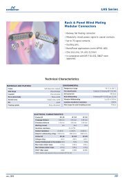
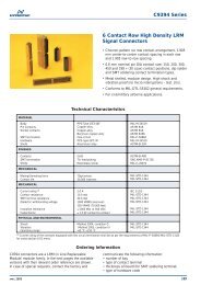
<strong>HBC</strong> <strong>power</strong> <strong>connector</strong><strong>Product</strong> <strong>description</strong>• <strong>Contact</strong> technology guarantees high reliability• Push lock to mate <strong>connector</strong>• Quick release latch to unmate• Ruggedised metal and plastic versions available• Cable and panel mount variants• Compact ergonomic design• Low component count• Gender reversible• Polarised• 360 degree EMI/RFI shielding option• 2000+ mating cycles without EMI/RFI band• Sealed IP67 when mated• Finger protected contacts• Current rating 300A and 500A• Temperature rating -20 to +125degCPage 1 of 16
1. Ordering information1.1. Connector order codeThe order code is a sixteen character code that defines all standard <strong>connector</strong>options in the range.<strong>HBC</strong>030 P A 1 A * A A 000Series<strong>HBC</strong>Current rating030050Shell genderPRShell polarisingABCShell material1BHigh <strong>power</strong> industrial300 Amp500 AmpPlugReceptaclePolarised Code A, contact cap blackPolarised Code B, contact cap orangePolarised Code C, contact cap blueHigh strength thermoplastic body, blackHigh strength aluminium alloy body,electroless nickel plated00000E0C00J00M00N0Standard variationsNo variantEMI band fitted (metal plugs only)Rear mount metal receptacle withconductive panel o-ringFront mount plastic receptacle withnon-conductive panel gasketFront mount metal receptacle withconductive panel o-ring (notavailable with backshell option B)Front mount metal receptacle withnon-conductive panel o-ring (notavailable with backshell option B)Backshell exit code – see illustration below0 No backshell or metal <strong>connector</strong>OthercodesSee Backshell code table(section 1.3)<strong>Contact</strong> genderAB<strong>Contact</strong> termination*LPin, gold platedSocket, gold plated<strong>Contact</strong> to accept cable crimpeddirectly on contact axis. See table Nonremovablestraight exit crimpcontacts on following page.<strong>Contact</strong> to accept bolted terminatione.g. lugged cable (lug orderedseparately, see Accessories - Crimplug codes below) or busbar. Also orderthis option for a plug with right anglebackshell.0ABCBackshell optionsNo backshellRight angle backshell (plug only)Straight backshell (metal versionsonly)Plastic receptacle to accept bootNote: plug <strong>connector</strong>s suppliedwithout backshells are designed toaccept lipped heat shrink bootsPage 2 of 16
1.2. Non-removable straight crimp contactsCrimp contact size codesCode 300 amp <strong>connector</strong> 500 amp <strong>connector</strong>Conductorsize (mm²)Crimp barrelbore (mm)Conductorsize (mm²)Crimp barrelbore (mm)B 25 7.0 50 10.0D 25 7.9 50 11.0H - - 70 13.0K 35 9.2 - -Q - - 95 14.5S 50 11.0 - -V - - 120 15.01.3. Backshell exit angle illustrationImportant: This section applies to plastic-bodied right-angle backshell plugs only.Right-angle backshells for plastic-bodied plugs are factory fitted and non-adjustable.The exit angle is related to the position of the red alignment marks printed on theplug and receptacle bodies. When the <strong>connector</strong>s are mated, the cable will emergefrom the plug at a specified angle. The standard angle is zero degrees. Other anglesare available in 15 degree increments to account for a wide range of panel and cablelayouts; see table below.AlignmentmarksStandard zero degreeposition (code A)135°Backshell code KA 0° G 90° N 180° U 270°B 15° H 105° P 195° V 285°C 30° J 120° Q 210° W 300°D 45° K 135° R 225° X 315°E 60° L 150° S 240° Y 330°F 75° M 165° T 255° Z 345°Page 3 of 16
2. AccessoriesIf required, the following accessories must be ordered separately; they are notsupplied with <strong>connector</strong>s.2.1. Crimp lug codes and dimensionsLug for standard cable (suffix –A-68)Lug for fine stranded cable (suffix –B-68)Important: These are special pattern <strong>Hypertac</strong> lugs which must be used on all<strong>connector</strong>s with right-angle backshells. They are also recommended for use on plug<strong>connector</strong>s with bolted contact terminations and no backshells.Receptacle <strong>connector</strong>s where no boot is fitted can accept any other suitable lug.Crimp lugs are tin plated (suffix -68). Type “B” lugs are designed to be compatiblewith fine-stranded <strong>power</strong> cables e.g. IEC 60228, Class 5.Lugs require crimp tooling; see Spares and special tools section.LUG CODES & DIMENSIONS FOR 300A RANGEDimensionsCable area,A C D1 D2 E H Lsq mmPart Numbermax nom nom nom nom nom nomT ref25 HBB-950-8-25-A-68 18.1 10.0 7.0 10.0 25.0 8.3 38.1 4.025 HBB-950-8-25-B-68 18.1 10.0 7,9 11,0 27.0 8.3 40.4 4.035 HBB-950-8-35-A-68 18.1 10.0 8.5 12.0 25.0 8.3 39.0 4.035 HBB-950-8-35-B-68 18.1 10.0 9,2 12,5 27.0 8.3 41.0 4.050 HBB-950-8-50-A-68 18.1 10.0 10.0 14.0 25.0 8.3 39.6 4.050 HBB-950-8-50-B-68 18.1 10.0 11,0 15,0 27.0 8.3 41.9 4.070 HBB-950-8-70-A-68 18.1 10.0 12.0 16.5 25.0 8.3 40.5 4.070 HBB-950-8-70-B-68 18.1 10.0 13,0 17,0 27.0 8.3 42.5 4.0Page 4 of 16
Cablearea, sqmmLUG CODES & DIMENSIONS FOR 500A RANGEPart numberAmaxCnomD1nomDimensionsD2nomEnomHnomLnom50 HBB-950-10-50-A-68 20.1 12.0 10.0 14.0 25.0 10.3 41.5 4.550 HBB-950-10-50-B-68 20.1 12.0 11.0 15,0 27.0 10.3 43.8 4.570 HBB-950-10-70-A-68 20.1 12.0 12.0 16.0 25.0 10.3 42.1 4.570 HBB-950-10-70-B-68 20.1 12.0 13,0 17,0 27.0 10.3 44.4 4.595 HBB-950-10-95-A-68 20.1 12.0 13.5 18.0 25.0 10.3 42.8 4.595 HBB-950-10-95-B-68 20.1 12.0 14,5 19,0 27.0 10.3 45.1 4.5120 HBB-950-10-120-A-68 20.1 12.0 15.0 19.5 25.0 10.3 43.4 4.5120 HBB-950-10-120-B-68 20.1 12.0 16,2 21.0 27.0 10.3 45.8 4.52.2. Heat shrink bootsConnectors are designed to accept the following moulded lipped heat shrink bootswhich conform to specification number VG95343:TrefStraight boot for bare<strong>connector</strong>90° bootBoot for right anglebackshellBoot for straightbackshell300A plasticplugHBO-0008-B005A(see note A)HBO-0009-E004A(see note B)HBO-0008-B004A(see note C)N/A300A plasticreceptacleHBO-0008-B004A(see note C)HBO-0009-E003A(see note D) * orHBO-0009-E004A(see note B) *N/AN/A300A metalplugHBO-0008-B005A(see note A)HBO-0009-E004A(see note B)HBO-0008-B005A(see note A)HBO-0008-B005A(see note A)300A metalreceptacleN/A N/A N/AHBO-0008-B005A(see note A)500A plasticplugHBO-0008-C001A(see note F)HBO-0009-E005A(see note E)HBO-0008-B005A(see note A)N/A500A plasticreceptacleHBO-0008-B005A(see note A)HBO-0009-E004A(see note B) * orHBO-0009-E005A(see note E) *N/AN/A500A metalplugHBO-0008-C001A(see note F)HBO-0009-E005A(see note E)HBO-0008-C001A(see note F)HBO-0008-C001A(see note F)500A metalreceptacleN/A N/A N/AHBO-0008-C001A(see note F)Notes* If a <strong>Hypertac</strong> lug is used, then use the smaller boot.A: VG spec = VG 95343 T18 B005A D: VG spec = VG 95343 T18 E003AB: VG spec = VG 95343 T18 E004A E: VG spec = VG 95343 T18 E005AC: VG spec = VG 95343 T18 B004A F: VG spec = VG 95343 T18 C001APage 5 of 16
It is the user’s responsibility to ensure that boot material and adhesive / epoxy meetthe requirements of their application.For further application details see Workshop Manual – single-pole HBB and <strong>HBC</strong>range available from website or <strong>Hypertac</strong> technical services.2.3. Heat shrink tubesOn the following <strong>connector</strong> types, an insulating sleeve must be fitted to crimp lugs orcrimp barrels. Thick-walled adhesive-lined heat shrink tube meeting VG95343 is therecommended material for this application. Sleeves must be fitted prior to fitting oneof the above heat shrink boots. Tubing must cover the entire crimp barrel and seal tothe cable outer jacket.300A plastic plug with 90 degree boot300A plastic receptacle with 90 degree boot300A metal plug, all options300A metal receptacle, straight backshell500A plastic plug with 90 degree bootwith 50 sq mm cablewith cable >50 sq mm500A plastic receptacle with 90 degree bootwith 50 sq mm cablewith cable >50 sq mm500A metal plugall options with 50 sq mm cableall options with cable >50 sq mm500A metal receptacle, straight backshellall options with 50 sq mm cableall options with cable >50 sq mm<strong>Hypertac</strong> pt. no.HBO-0007-D006A-0050HBO-0007-D006A-0050HBO-0007-D006A-0050HBO-0007-D006A-0050HBO-0007-D006A-0070HBO-0007-D007A-0070HBO-0007-D006A-0070HBO-0007-D007A-0070HBO-0007-D006A-0070HBO-0007-D007A-0070HBO-0007-D006A-0070HBO-0007-D007A-0070Tubing ordered according to this table is made from a self-extinguishing elastomer,internally coated with high-performance epoxy. The material/adhesive combination israted to 150 degrees C. It is the user’s responsibility to ensure that tube material andadhesive/epoxy meet the requirements of their application.For further application details see Workshop Manual – single-pole HBB and <strong>HBC</strong>range available from website or <strong>Hypertac</strong> technical services.2.4. Screen braid clamps2.4.1. Band-It, stainless steel, passivatedBand-It clamp suitable for:300A <strong>connector</strong> with straight or right angle backshell500A <strong>connector</strong> with straight or right angle backshell<strong>Hypertac</strong> pt. no.HBO-0005HBO-0005Band-It clamps require an installation tool; see Spares and special tools section fortool order codes.Page 6 of 16
2.4.2. Constant force spring clamp, stainless steel, pre-stressed and heattreatedConstant force clamp suitable for:300A <strong>connector</strong> with straight or right angle backshell500A <strong>connector</strong> with straight or right angle backshell<strong>Hypertac</strong> pt. no.HBB-971HBB-971No tooling is required for constant force clamps. These clamps are removable andre-useable.3. Spares and special tools3.1. Spare parts3.1.1. Receptacle interface o-ringsFluorosilicone o-ring for 300A metal receptacleFluorosilicone o-ring for 500A metal receptacle<strong>Hypertac</strong> pt. no.HR-01560-0178-F-70HR-02350-0178-F-703.1.2. Panel o-ringsFluorosilicone o-ring for 300A metal receptaclesFluorosilicone o-ring for 500A metal receptaclesFluorosilicone o-ring for 300A plastic receptaclesFluorosilicone o-ring for 500A plastic receptaclesConductive o-ring for 300A metal receptaclesConductive o-ring for 500A metal receptacles<strong>Hypertac</strong> pt. no.HR-02987-0178-F-70HR-03782-0178-F-70HR-03108-0178-F-70HR-03782-0178-F-70HR-02987-0178-D-70HR-03782-0178-D-703.1.3. Panel gasketsMoulded fluorosilicone gasket for 300A plastic receptaclesMoulded fluorosilicone gasket for 500A metal receptacles<strong>Hypertac</strong> pt. no.HBB-942-MHBB-943-M3.1.4. Backshell cap o-ringsFluorosilicone o-ring for 300A metal right-angle backshellFluorosilicone o-ring for 500A metal right-angle backshellFluorosilicone o-ring for 300A plastic right-angle backshellFluorosilicone o-ring for 500A plastic right-angle backshell<strong>Hypertac</strong> pt. no.HR-02195-0178-F-70HR-02670-0178-F-70HR-02300-0200-F-70HR-02800-0200-F-70Page 7 of 16
3.2. Special tools3.2.1. Band-It toolingHand tool for Band-It screen braid clamps<strong>Hypertac</strong> pt. no.HBO-00063.2.2. Crimp toolingKlauke crimp tooling is recommended for terminating cables to <strong>connector</strong> crimpbarrels and terminal lugs.Battery <strong>power</strong>ed tool (mini electro-hydraulic) = Klauke ® EK354.Crimp tools and dies listed in the following tables to be sourced from Klauke ® .3.2.3. Crimp dies by code/lug and cable size – 300A rangeTermination code or lugrefCableCSA(mm²)Crimpbarrel ID(mm)CrimpstyleNo. ofcrimpsDie for usewith EK354toolD 25 7.9 Hex 2 HR425K 35 9.2 Hex 2 HR435S 50 11.0 Hex 2 HR450HBB-950-8-25-A-68 25 7.0 Hex 2 HR425HBB-950-8-25-B-68 25 7.9 Hex 2 HR425HBB-950-8-35-A-68 35 8.5 Hex 2 HR435HBB-950-8-35-B-68 35 9.2 Hex 2 HR435HBB-950-8-50-A-68 50 10.0 Hex 2 HR450HBB-950-8-50-B-68 50 11.0 Hex 2 HR450HBB-950-8-70-A-68 70 12.0 Hex 2 HR470HBB-950-8-70-B-68 70 13.0 Hex 2 HR4703.2.4. Crimp dies by code/lug and cable size – 500A rangeTermination code or lugrefCableCSA(mm²)Crimpbarrel ID(mm)CrimpstyleNo. ofcrimpsDie for usewith EK354toolD 50 11.0 Hex 2 HR450H 70 13.0 Hex 2 HR470Q 95 14.5 Hex 2 HR495V 120 15.0 Hex 2 HR4120HBB-950-10-50-A-68 50 10.0 Hex 2 HR450HBB-950-10-50-B-68 50 11.0 Hex 2 HR450HBB-950-10-70-A-68 70 12.0 Hex 2 HR470HBB-950-10-70-B-68 70 13.0 Hex 2 HR470HBB-950-10-95-A-68 95 13.5 Hex 2 HR495HBB-950-10-95-B-68 95 14.5 Hex 2 HR495HBB-950-10-120-A-68 120 15.0 Hex 2 HR4120HBB-950-10-120-B-68 120 16.2 Hex 2 HD4120Page 8 of 16
4. Panel preparations and <strong>connector</strong> outline drawings4.1. Panel preparation for receptacles4.1.1. Standard rear mount (<strong>connector</strong> mounted behind panel / inside box)300 amp metal 300 amp plastic500 amp metal 500 amp plasticMaximum panel thickness 5.0mm.If panel is more than 3.0mm thick then fixing screws will need to be recessed to giveclearance for mating <strong>connector</strong>.Page 9 of 16
4.1.2. Outer mounting (<strong>connector</strong> mounted in front of panel / outside box)300 amp metal & plastic 500 amp metal & plasticPage 10 of 16
4.2. Connector outline drawings4.2.1. 300 amp plastic plug – <strong>HBC</strong>030P*1*******4.2.2. 300 amp plastic receptacle – <strong>HBC</strong>030R*1*******Dimensions in mmTransit caps not shownPage 11 of 16
4.2.3. 300 amp metal plug – <strong>HBC</strong>030P*(A or B)*******4.2.4. 300 amp metal receptacle – <strong>HBC</strong>030R*(A or B)*******Dimensions in mmTransit caps not shownPage 12 of 16
4.2.5. 500 amp plastic plug – <strong>HBC</strong>050P*1*******4.2.6. 500 amp plastic receptacle – <strong>HBC</strong>050R*1*******STRAIGHT CRIMP STANDARD BOOT VARIANTDim A 43,6 58,9Dimensions in mmTransit caps not shownPage 13 of 16
4.2.7. 500 amp metal plug – <strong>HBC</strong>050P*(A or B)*******4.2.8. 500 amp metal receptacle – <strong>HBC</strong>050R*(A or B)*******Dimensions in mmTransit caps not shownPage 14 of 16
4.3. Mated dimensionsDimension when fully mated, mm D MAX300A metal 13300A plastic 13500A metal 13.5500A plastic 13.54.4. Metal backshell dimensions4.4.1. Straight option (optional knurl on ØC)Dimensions in mm A B ØC ØD ØE F G ØH300A straight 6 20 25 27 28 13 5 22500A straight 9.5 20 34 36 38 13 5 30Page 15 of 16
4.4.2. Right-angle option (optional knurl on ØC)Dimensions in mm A B ØC ØD ØE F G ØH J300A right-angle 5 20 30 32 33 13 5 27 43500A right-angle 4 20 35 37 39 13 5 32 475. Cable assembliesConnectors can be supplied terminated to a range of cables. Refer to <strong>Hypertac</strong> salesor technical services for details.Page 16 of 16