Technical Brochure - Magnetrol International
Technical Brochure - Magnetrol International
Technical Brochure - Magnetrol International

You also want an ePaper? Increase the reach of your titles
YUMPU automatically turns print PDFs into web optimized ePapers that Google loves.
Horizontal FloatA horizontal float switch, often called a side mountedunit, operates much like a vertical float. It utilizes thesame components, float, stem, sleeve, ➀ enclosing tube, ➁switch magnet ➂ and mechanism, but functions in aslightly different manner. The lower float stem pivotson a fulcrum. This means that as the float rises, theattraction sleeve is pulled down out of the field of theswitch magnet causing the magnet to be pulled awayfrom the enclosing tube. Conversely, as the float falls,the sleeve moves upward causing the switch magnet topull in. Side mounted controls may be used for widelevel differential. By lengthening the float stem, theliquid level and float must move through a greater distancein order to change the state of the switch. Sidemounted units offer the option of mounting towardthe bottom of a vessel for use in low level service,something that may not be done with a top mountedvertical float.Displacer SwitchesWhile taking advantage of the same buoyancy andmagnetic coupling principles as float switches, displacerlevel switches utilize a precision range spring ➃ to convertthe change in buoyancy force to movement of anattraction sleeve. ➀ Because the displacer ➄ is weighted,it hangs into the liquid rather than floating on top. Asthe liquid level moves changing the volume of liquiddisplaced by the displacers, the buoyancy force on thedisplacers changes. This causes elongation or compressionof the range spring which, in turn, moves theattraction sleeve into or out of the field of the switchmagnet, changing the state of the switch. ➅ 5Displacers
Buoyancy Level Controls (continued)Displacer Transmitters6As with displacer switches, the change in buoyancyforce on a range spring is converted to motion in a displacertransmitter. This motion is used to produce anoutput proportional to the change in liquid level. Thepneumatic Modulevel has a sleeve that attracts a followermagnet, changing the position of a nozzle lever andthe output from the controller head. The E3 Modulevelemploys a linear variable differential transformer (LVDT)to produce the proportional output. The core of theLVDT is fixed to the top of the displacer stem. As theWiring BoardMovingLVDT CorePrintedCircuit BoardEnclosing TubeRange SpringElectronicsEnclosureLVDTDisplayKeypadStemDisplacerExternal cagespring compresses or elongates, the core moves withinthe LVDT windings, inducing currents in the secondarywindings. This information is processed and output as a4–20 mA proportional signal. In addition, the E3 superimposesa HART ® compatible signal on the 4–20 mAallowing communications via the HART protocol or isavailable with FOUNDATION fieldbus protocol.Advantages (+) and Limitations (-)Vertical Float :+ Highly reliable and repeatable+ Broad product offering+ High temperature capability+ Many modifications and options available- Low S.G. means a low pressure rating- Only narrow differential standard- External cage units are expensive when largefloats (and therefore cages) are requiredHorizontal Float:+ Highly reliable and repeatable+ Wide or narrow differentials+ Low S.G. rating on counterweighted units- Invasive mounting; can’t be isolated withoutadditional chamber- Use only on very clean liquids due to pivots inthe processDisplacer Switches:+ Highly reliable and repeatable+ Wide and narrow differentials or combinations+ High pressure capability with low S.G.+ Not affected by turbulence- Temperature limited by range springDisplacer Transmitters:+ High pressure/temperature capabilities+ Stable signal in turbulent applications+ No flexure of pressure boundary parts+ HART or FOUNDATION fieldbus compatible- Affected by shifting S.G.
▼▼▼▼<strong>Magnetrol</strong>’s Buoyancy ProductsThe chart below summarizes theprinciple features of <strong>Magnetrol</strong>’sleading buoyancy products. A green dot(•) indicates a standard feature; a redtriangle (▲) indicates an optional feature.Tuffy II SwitchesSide Mount Float SwitchesTop Mount Float SwitchesTop Mount Displacer SwitchesExternal Cage Displacer SwitchesExternal Cage Float SwitchesSeries 3 SwitchesAurora Level GaugeModulevel PneumaticModulevel Digital E3Boiler SwitchesFlow SwitchesTK1 SwitchesSensor TypeControlAction/OutputConfigurationsConstructionto CodePage NumberFloatDisplacerSingle SwitchMultiple SwitchControllerTransmitterNarrow SwitchDifferentialWide SwitchDifferentialIndicatorHARTFOUNDATION FieldbusExternal CageTop MountSide MountIntegral MountRemote MountNACE ConstructionASME B31.1ASME B31.38 9 10 11 12 12 13 14 15 16 17 18 19• • • • • • • •• • • • •▲• • • • • • • • • •▲ ▲ • • • • • ••• •▲▲ ▲• • • • • • • • • •• • •• •▲▲• • •• • • • • •▲ ▲ ▲ •• •▲• • •▲• • • •• • • • • • • • • • • • •▲ ▲ ▲▲ ▲ ▲•▲ ▲ ▲•▲▲ ▲ ▲•▲▲ ▲ ▲•▲ ▲ ▲ ▲•7
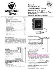
E3 MODULEVEL ®Advanced Level ControlElectronic TransmitterDescription:Features:Model Selection:The E3 Modulevel level transmitter is an advanced, intrinsically-safe, twowireinstrument that converts liquid level changes into a stable outputsignal. It has microprocessor-based electronics with HART compatibleoutput or FOUNDATION fieldbus with a PID block. E3 supports theFDT/DTM standard and PACTware PC software package.• Two-wire, loop-powered, transmitter for level, interface or densitymeasurement• No level change needed for configuration; no field calibration necessary.• Suitable for use in Safety Integrity Level (SIL) 2 environments with anSFF of 92.3%• 4–20 mA output signal• Two-line, 8-character LCD and 3-button keypad• Continuous self-test, 3.6 mA, 22 mA or HOLD fault indication and fullyNAMUR NE 43 compliant• Comprehensive diagnostics with faults, warnings & status history• HART or FOUNDATION fieldbus digital communications• PACTware PC program using HART communication for advancedconfiguration and troubleshooting (see bulletin 59-101)• IS, XP and Non-incendive approvals from FM, CSA, ATEX, IEC• Standard output range from 3.8 to 20.5 mA• 11 VDC turn on voltage• Maximum loop resistance of 620 ohms at 24 VDC• Refer to <strong>Magnetrol</strong> Bulletin 48-135 for model numbers, options andcomplete specification information.SIL 2SFF 92.3%S P E C I F I C A T I O N SSupply Voltage:11 to 36 VDCAmbient Temp Range: –40° to +176° F (–40° to +80° C)Process Temp Range: Steam Applications: –20° to +500° F (–29° to +260° C)Non-Steam Applications: –20° to +600° F (–29° to +315° C) with carbon steel chambers;stainless steel chambers available for lower process temperaturesProcess Pressure: Up to 5100 psig @ +100° F (352 bar @ +38° C)Accuracy:Repeatability:Linearity:±0.75 % of full span±0.05 % of full span±0.50 % of full spanTemperature Effect: Max 0.017 %/° F (0.031 %/° C) from -40° F to +176° F (-40° C to +80° C)8Operator Interface:Output:Specific Gravity:Materials of Construction:HART Handheld Communicator, PACTware PC software and Field Device Tool, or 3-buttonmenu-driven data entry and system security with 2-line × 8-character LCD display4–20 mA (reversible) with HART; max loop resistance 620 Ω @ 24 VDC;3.8 to 20.5 mA usable (meets NAMUR NE43) or FOUNDATION fieldbus0.23 to 2.20 SGChambers: carbon steel or 316/316L stainless steelWetted Components: 316/316L and Inconel ® (spring)
MODULEVEL ®Pneumatic ControllerHigh Reliability in Temperature and Pressure ExtremesDescription:Features:Model Selection:The pneumatic Modulevel is a highly reliable liquid level controllerusing continuous displacement technology. The output signals arein direct proportion to changes in liquid level. The pneumaticModulevel uses <strong>Magnetrol</strong>’s proven magnetic coupling design foroptimum performance at extreme temperature and pressure.• Range spring design provides stable output signal even on turbulentlevel, reducing valve wear.• Head rotates 360° for ease of installation and positioning.• NEMA 3R controller head is removable without depressurizing theprocess, reducing downtime and maintenance costs.• Instrument shop calibration allows quick start-up or maintenance.• Visual indicator is actuated by magnetic coupling which allowsvisual level indication even upon loss of air supply.• Turndown, midpoint change, and specific gravity correction are alladjusted by dedicated calibrators making start-up quick and easy.• Suitable for interface level with modified displacer.• Dual head, receiver/controllers are standard selection.Refer to <strong>Magnetrol</strong> Bulletin 48-110 for model numbers, options andcomplete specification information.S P E C I F I C A T I O N SSupply Pressure:Air Consumption:Process Temp Range:Regulated instrument quality air (clean & dry)3 SCFH @ 9 psig output6 SCFH @ 15 psig output-20° to +700° F (-29° to +371° C) with carbon steel chambers(stainless steel chambers are available for lower process temperatures)Process Pressure: Up to 4265 psig @ +100° F (294 bar @ +38° C)Accuracy:
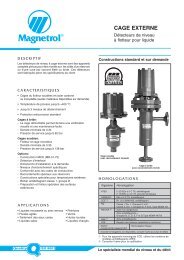
EXTERNAL CAGE Liquid Level SwitchesReliability in Sealed or Flanged Top External ChambersDescription:Measurement Principle:Features:Model Selection:<strong>Magnetrol</strong>’s external cage float and displacer actuated levelswitches have been industry standards for decades. With 28 basicmodels from which to choose, these self-contained instrumentsprovide time-proven solutions to a wide range of level controlapplications.Vertical float or displacer actuated level switch.• Sealed and flanged top external chambers• Broad selection of switch types• Single or multiple switch points• Exotic materials of construction available• Can be modified for interface service• Available with many sizes, types and configurations of processconnections, including optional weld neck, RTJ or DIN flanges.• All switch enclosures rotate through 360° for ease of conduitentry positioning.Refer to <strong>Magnetrol</strong> bulletins 46-115, 46-116 and 46-121 for modelnumbers, options and complete specification information.S P E C I F I C A T I O N SProcess Temp Range: –50° to +1000° F (–29° to +538° C)Process Pressure:Float controls up to 2240 psig (154 bar)Displacer controls up to 5000 psig (345 bar)Specific Gravity: Down to 0.32Chamber Material:Float and Trim Parts:Standard is carbon steel. Sealed cage models available in stainless steel.Options include 304/304L SS, 316/316L SS, Monel, Hastelloy C,duplex SS, etc.300 and 400 series SS or all 316/316L SSSwitch Enclosures: Polymer power coat finished aluminum NEMA 4X/7/9 for Class I, Div. 1,Group B or Groups C & D areas, IEC Ex Ex d IIC T6 IP66 areas andATEX Ex II 2 G EEx d IIC T6.Switch Mechanisms:Options:Dry contact, hermetically sealed, and pneumaticInterface service, high and low temperature modifications, customizedinstallation dimensions, vents and drains, customized actuation levels,special finishes, etc.12
TOP MOUNT DISPLACER TYPE Level SwitchesNarrow or Wide Range; for Simple or Complex ApplicationsDescription:Measurement Principle:Features:Model Selection:<strong>Magnetrol</strong>’s displacement type level switches offer the user a wideselection of alarm and control configurations. These switches arewell suited for simple or complex applications from single alarmspoints to overlapping three stage pump control.Vertical displacer actuated level switch.• Reliable, maintenance-free operation• Single, dual or triple stage models• 16 standard displacer arrangements plus specials• Field-adjustable set points and deadband• Verify switch operation with the optional Proofer ground checker• Models available for floating roof detection• Range spring design allows for reliable performance even inturbulent or surging applications.• Models built to NACE MR0175 and MR0103 available• Available with a variety of electric and pneumatic switchmechanismsRefer to <strong>Magnetrol</strong> Bulletin 45-115 for model numbers, optionsand complete specification information.S P E C I F I C A T I O N SProcess Temp Range: –50° to +500° F (–46° to +260° C)Process Pressure:Up to 800 psig (55 bar)Specific Gravity Range: 0.40 to 2.40Wetted Parts:Actuation Levels:Mounting connection in carbon steel, cast iron or 316/316L SSDisplacers in 316/316L SS, porcelain, Karbate or leadTrim in 300 and 400 series SS or, all 316/316L SSDisplacer cable and clamps in 316/316L SS, Monel or Hastelloy COne to three narrow and wide differential set points, field-adjustable.Switch Enclosures: Polymer power coat finished aluminum NEMA 4X/7/9 for Class I, Div. 1,Group B or Groups C & D areas, IEC Ex Ex d IIC T6 IP66 areas andATEX Ex II 2 G EEx d IIC T6.Switch Mechanisms:Options:Dry contact, hermetically sealed, and pneumaticModification per customer requirements include extended displacercable, interface service, low specific gravity displacers, customizeddisplacer arrangements, etc.13
TOP MOUNT Liquid Level SwitchesSimple and Reliable Float Actuated Switches for Top Mount InstallationsDescription:Measurement Principle:Features:Model Selection:Top mounted, float actuated models T20 and T21 providetime-tested reliability in a single or dual stage liquid level switch.These simple vertical float switches are easy to install and requirevirtually no maintenance making them cost-effective processcontrol instruments.Vertical float actuated level switch.• Reliable, maintenance-free operation• Single or dual stage models• Actuating levels as low as 48" (1.2 m) below mounting connection• Choice of floats allows application flexibility• Threaded or flanged process connections available• Available with a variety of electric and pneumatic switchmechanismsRefer to <strong>Magnetrol</strong> Bulletin 44-117 for model numbers, options andcomplete specification information.S P E C I F I C A T I O N SProcess Temp Range: –50° to +1000° F (–46° +538° C)Process Pressure:Up to 600 psig (41 bar)Specific Gravity: Down to 0.56Wetted Parts:Actuation Levels:Mounting connection in carbon steel, cast iron or 316/316L SSFloat and trim in 300 and 400 series SS or all 316/316L SSEach unit built and calibrated for customer specified actuation level(s)from 4 to 48 inches (101 mm to 1.2 m) from mounting connection.Minimum distance between trip points on dual stage units is 8" (203 mm).Switch Enclosures: Polymer power coat finished aluminum NEMA 4X/7/9 for Class I, Div. 1,Group B or Groups C & D areas, IEC Ex Ex d IIC T6 IP66 areas andATEX Ex II 2 G EEx d IIC T6.Switch Mechanisms:Guide Cage:Options:Dry contact, hermetically sealed, and pneumaticOptional guide cage prevents damage to float or stem in turbulentinstallations or on long insertion length models.Modification per customer requirements include interface service, lowspecific gravity floats, other process connections, etc.14
SIDE MOUNT Liquid Level SwitchesReliable Float Actuated Switches for Side Mount InstallationsDescription:Measurement Principle:Features:Model Selection:Single and dual stage side mounted float level switches are availablewith a wide choice of mounting connections, stem lengths,floats and switch options to provide reliable solutions to a broadrange of level control applications.Horizontal float actuated level switch.• Single or dual stage models• Narrow to wide differential for a variety of control needs• Choice of six float and four stem sizes allows applicationflexibility• Threaded or flanged process connections available• Available with a variety of electric and pneumatic switchmechanisms.Refer to <strong>Magnetrol</strong>Bulletin 44-116 formodel numbers,options and completespecification information.S P E C I F I C A T I O N SProcess Temp Range: –50° to +1000° F (–46° to +538° C)Process Pressure:Up to 1200 psig (83 bar)Specific Gravity: Down to 0.40Wetted Parts:Actuation Levels:Body in carbon steel, 304 SS or 316 SS.Float and trim in 300 and 400 series SS or all 316/316L SS.Level differential from as narrow as 1.00" to as wide as 16.12" is availableon single stage models.Switch Enclosures: Polymer power coat finished aluminum NEMA 4X/7/9 for Class I, Div. 1,Group B or Groups C & D areas, IEC Ex Ex d IIC T6 IP66 areas andATEX Ex II 2 G EEx d IIC T6.Switch Mechanisms:Options:Dry contact, hermetically sealed, and pneumaticModification per customer requirements include interface service, exoticmaterials of construction, etc.15
TUFFY ® II Liquid Level SwitchesA Compact Horizontal Mount Float SwitchDescription:Measurement Principle:Features:Model Selection:A single stage, compact float level switch for horizontal mounting into a tank or vessel through threaded orflanged pipe connections.Horizontal float-actuated level switch.• Enlarged switch housing for ease of wiring• Narrow and adjustable differential models to suit any application• Unique model for interface• Available built to ASME B31.3, NACE or both• Choice of cast iron or aluminum switch enclosure materials• Selection of switch types, both gold and silver contacts• Model available with all Hastelloy C wetted components• Clad flange design includes 3" to 6" sizes up to 1500# ANSIRefer to <strong>Magnetrol</strong> Bulletin 44-106 for model numbers, options and complete specification information.S P E C I F I C A T I O N SProcess Temp Range: –65° to +750° F (–54° to +399° C)Process Pressure:Up to 2625 psig (181 bar)Specific Gravity: Down to 0.40Wetted Parts:Models available with 316/316L SS or Hastelloy C wetted partsLevel Differential: Models available with narrow (0.5") to wide differential (up to 18.26")Switch Enclosures: Polymer powder coat finished cast iron or aluminum NEMA 4X/7/9 for Class I Div. 1 Group B, C & D,and ATEX Ex II 1/2 G EEx d IIC T6 and Ex II 1G EEx ia IIC T6Switch Mechanisms:SPDT and DPDT dry contact gold or silver, or SPDT hermetically sealed gold or silverInterface Level: Minimum specific gravity difference of 0.10 and minimum lower liquid specific gravity of 0.81External Cage:Pneumatic Tuffy:Optional cage in carbon steel or 316 SS for use when unit cannot be mounted directly into tank or vesselSee bulletin 44-109 for models and specifications16
MODEL TK1 Liquid Level SwitchesA Compact Horizontal Mount Float SwitchDescription:A single stage, compact floatlevel switch for horizontalmounting into a tank or vesselthrough threaded or flangedpipe connections.Measurement Principle:Features:Model Selection:Horizontal float actuated levelswitch.• Sealed reed switches or DPDT relays available• Choice of flying leads or junction box• All 316 SS wetted parts• Explosion proof with or without ajunction box• Extended stem model for deepmountings• A selection of threaded and flangedprocess connectionsavailableRefer to <strong>Magnetrol</strong> Bulletin 44-108 formodel numbers, options and completespecification information.S P E C I F I C A T I O N SProcess Temp Range: –40° to +300° F (–40° to +149° C)Process Pressure:Up to 1500 psig (103 bar)Specific Gravity: Down to 0.40Wetted Parts:Switch Enclosures:Switch Mechanisms:316/316L SS316/316L SS body and cast aluminum/iron junction boxSPST or SPDT reed switches and 24 VDC or 120 VAC DPDT powered relays17
SPECIAL PURPOSE Liquid Level SwitchesModel B40 LIQUID LEVEL SWITCHDescription:Measurement Principle:Features:The B40 is a float actuated liquid level switch designed for high pressureand temperature service. The sealed external cage houses a horizontallyoriented float assembly for use in single stage applications.Horizontal float actuated level switch.• Chambers in carbon steel, 316 SS, 304 SS and chrome moly• Optional construction to ASME B31.1 for use in power plantsProcess Temp Range: –50° to +1200° F (–29° to +649° C)Pressure Pressure:Model Selection:Up to 3300 psig (228 bar)Refer to <strong>Magnetrol</strong> Bulletin 46-120 for model numbers, options andcomplete specification information.Models F10 and F50 FLOW SWITCHESDescription:Measurement Principle:Features:The F10 and F50 are mechanical flow switches designed for use in horizontalflow lines. The F10 is a vane actuated flow switch for use in lines 2" andgreater in diameter. The F50 is a disc actuated flow switch for use in lines2" and smaller in diameter.Vane and disc actuated flow switches.• F10 mounting available threaded or flanged, carbon steel, 304 SS or316 SS• F50 body available in bronze or 316 SS• F10 actuation flow rate is field-adjustable• F50 requires no calibrationProcess Temp Range:Process Pressure:Model Selection:–50° to +450° F (–29° to +232° C) for F10–50° to +750° F (–29° to +399° C) for F50Up to 1000 psig (69 bar) for F10Up to 1150 psig (79 bar) for F50Refer to <strong>Magnetrol</strong> Bulletin 47-116 for model numbers, options andcomplete specification information.18
BOILER Level SwitchesProviding Reliable Boiler Controls Since 1932Description:Measurement Principle:Features:Model Selection:<strong>Magnetrol</strong> boiler level switches are the first choice of the largest boiler manufacturers.Single stage units provide reliable low water cut off while multiplestage water column style units provide boiler water level control.Vertical float-actuated level switch.• Reliable operation• Single or multiple switch points• Both fabricated and cast chambers available• Water columns with try-cock and gauge glass connections• Left hand and right hand water column mountings• Pressures up to 600 pounds working steam pressure• Available with a variety of electric and pneumatic switchmechanismsRefer to <strong>Magnetrol</strong> Bulletin 46-118 for model numbers, options andcomplete specification information.S P E C I F I C A T I O N SProcess Temp Range: –20° to +750° F (–29° to +399° C)Process Pressure:Up to 900 psig (62 bar)Specific Gravity: Down to 0.75Chamber Material:Float and Trim Parts:Actuation Levels:Cast iron or fabricated carbon steel chambersBrass chamber linersTrim in 300 and 400 series SS or all 316/316L SSOne to three narrow differential set pointsSwitch Enclosures: Polymer power coat finished aluminum NEMA 4X/7/9 for Class I, Div. 1,Group B or Groups C & D areas, IEC Ex Ex d IIC T6 IP66 areas andATEX Ex II 2 G EEx d IIC T6.Switch Mechanisms:Dry contact, hermetically sealed, and pneumatic19
CORPORATE HEADQUARTERS5300 Belmont Road • Downers Grove, Illinois 60515-4499 USAPhone: 630-969-4000 • Fax: 630-969-9489magnetrol.com • info@magnetrol.comEUROPEAN HEADQUARTERSHeikensstraat 6 • 9240 Zele, BelgiumPhone: 052 45.11.11 • Fax: 052 45.09.93BRAZIL: Av. Dr. Mauro Lindemberg Monteiro • 185-Jd. Santa Fé, Osasco • São Paulo CEP 06278-010CANADA: 145 Jardin Drive, Units 1 & 2 • Concord, Ontario L4K 1X7CHINA: Room #8008 • Overseas Chinese Mansion • 129 Yan An Road (W) • Shanghai 200040DEUTSCHLAND: Alte Ziegelei 2–4 • D-51491 OverathDUBAI: DAFZA Office 5AE 722, P.O. Box 293671 • Dubai, United Arab EmiratesINDIA: C-20 Community Centre • Janakpuri, New Delhi 110 021ITALIA: Via Arese, 12 • 20159 MilanoSINGAPORE: No. 48 Toh Guan Road East #05-123 • Enterprise Hub • Singapore 608586UNITED KINGDOM: Regent Business Centre • Jubilee Road • Burgess Hill, West Sussex RH15 9TL<strong>Magnetrol</strong> & <strong>Magnetrol</strong> logotype, Orion Instruments & Orion Instruments logotype, Modulevel ® , Aurora ® , and Tuffy ® , are registered trademarks of <strong>Magnetrol</strong> <strong>International</strong>.Monel ® and Inconel ® are registered trademarks of Special Metals Corporation. HART ® is a registered trademark of the HART Communication Foundation. Hastelloy ® is a registered trademark of Haynes <strong>International</strong>.Copyright © 2009 <strong>Magnetrol</strong> <strong>International</strong>. All rights reserved. Printed in the USA.Bulletin: 46-100.3 • Effective: January 2009