Campbell Scientific CR-1000 Datalogger - Precision Solar ...
Campbell Scientific CR-1000 Datalogger - Precision Solar ...
Campbell Scientific CR-1000 Datalogger - Precision Solar ...

Create successful ePaper yourself
Turn your PDF publications into a flip-book with our unique Google optimized e-Paper software.
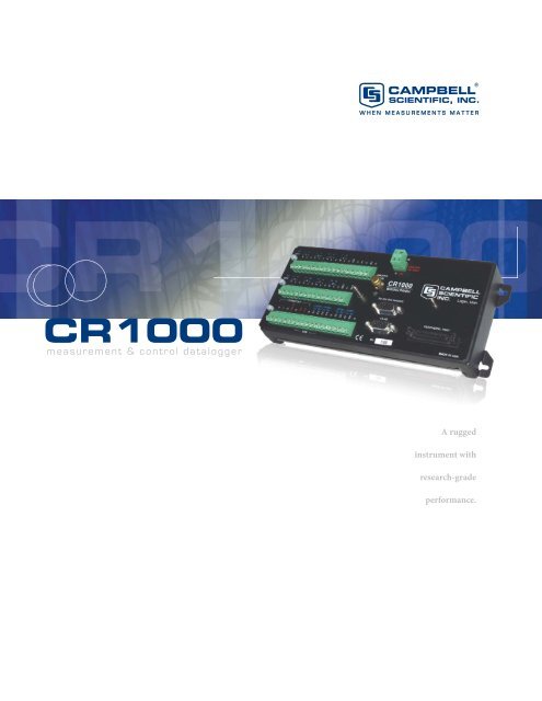
<strong>CR</strong><strong>1000</strong>Measurement and Control SystemThe <strong>CR</strong><strong>1000</strong> provides precision measurement capabilities in a rugged, battery-operated package. It consists of a measurement andcontrol module and a wiring panel. Standard operating range is -25° to +50°C; an optional extended range of -55° to +85°C is available.Input/Output Terminals—Individually configuredfor ratiometric resistivebridge, thermocouple,switch closure, high frequencypulse, low-level ac,serial sensors, and more.{Removable Power Terminal—simplifiesconnection to external power supply.RS-232—providesa 9-pin DCE portfor connecting abattery-poweredlaptop, serialsensors or RS-232modems.CS I/O Port—connects withAC-powered PCs and communicationperipherals suchas phone, RF, short-haul, andmultidrop modems.Peripheral Port—allows data to bestored on a CompactFlash card and/orsupports Ethernet communications.Features• 4 Mbyte memory*• Program execution rate of up to 100 Hz• CS I/O and RS-232 serial ports• 13-bit analog to digital conversions• 16-bit H8S Renesas Microcontroller with 32-bitinternal CPU architecture• Temperature compensated real-time clock• Background system calibration for accurate measurementsover time and temperature changes• Single DAC used for excitation and measurementsto give ratio metric measurements• Gas Discharge Tube (GDT) protected inputs• Data values stored in tables with a time stamp andrecord number• Battery-backed SRAM memory and clock ensuringdata, programs, and accurate time are maintainedwhile the <strong>CR</strong><strong>1000</strong> is disconnected from its mainpower source• Serial communications with serial sensors anddevices supported via I/O port pairs• PakBus, Modbus, DNP3, TCP/IP, FTP, and SMTPprotocols supportedMeasurement and Control ModuleThe module measures sensors, drives direct communicationsand telecommunications, reduces data, controlsexternal devices, and stores data and programs inon-board, non-volatile storage. The electronics are RFshielded and glitch protected by the sealed, stainlesssteel canister. A battery-backed clock assures accuratetimekeeping. The module can simultaneously providemeasurement and communication functions. Theon-board, BASIC-like programming language supportsdata processing and analysis routines.Wiring PanelThe <strong>CR</strong><strong>1000</strong>WP is a black, anodized aluminum wiringpanel that is compatible with all <strong>CR</strong><strong>1000</strong> modules. Thewiring panel includes switchable 12 V, redistributedanalog grounds (dispersed among analog channelsrather than grouped), unpluggable terminal block for12 V connections, gas-tube spark gaps, and 12 V supplyon pin 8 to power our COM-series phone modemsand other peripherals. The control module easily disconnectsfrom the wiring panel allowing field replacementwithout rewiring the sensors. A description ofthe wiring panel’s input/output channels follows.*Originally, the standard <strong>CR</strong><strong>1000</strong> had 2 MB of data/program storage, and an optional version, the <strong>CR</strong><strong>1000</strong>-4M, had 4 MB of memory. In September2007, the standard <strong>CR</strong><strong>1000</strong> started having 4 MB of memory, making the <strong>CR</strong><strong>1000</strong>-4M obsolete. <strong>Datalogger</strong>s that have a module with a serial numbergreater than or equal to 11832 will have a 4 MB memory. The 4 MB dataloggers will also have a sticker on the canister stating “4M Memory”.2
Analog InputsEight differential (16 single-ended) channels measurevoltage levels. Resolution on the most sensitiverange is 0.67 µV.Pulse CountersTwo pulse channels can count pulses from high level(5 V square wave), switch closure, or low level AC signals.Switched Voltage ExcitationsThree outputs provide precision excitation voltages forresistive bridge measurements.Digital I/O PortsEight ports are provided for frequency measurements,digital control, and triggering. Three of these ports canalso be used to measure SDM devices. The I/O portscan be paired as transmit and receive. Each pair has 0to 5 V UART hardware that allows serial communicationswith serial sensors and devices. An RS232-tologiclevel converter may be required in some cases.CS I/O PortAC-powered PCs and many communication peripheralsconnect with the <strong>CR</strong><strong>1000</strong> via this port. Connection toan AC-powered PC requires either an SC32B or SC-USBinterface. These interfaces isolate the PC’s electricalsystem from the datalogger, thereby protecting againstground loops, normal static discharge, and noise.RS-232 PortThis non-isolated port is for connecting a batterypoweredlaptop, serial sensor, or RS-232 modem.Because of ground loop potential on some measurements(e.g., low level single-ended measurements),AC-powered PCs should use the CS I/O port instead ofthe RS-232 port (see above).Peripheral PortOne 40-pin port interfaces with the NL115 EthernetInterface & CompactFlash Module, the NL120 EthernetInterface, or the CFM100 CompactFlash® Module.Switched 12 VoltThis terminal provides unregulated 12 V that can beswitched on and off under program control.Storage CapacityThe <strong>CR</strong><strong>1000</strong> has 2 MB of flash memory for the OperatingSystem, and 4 MB of battery-backed SRAM for CPUusage, program storage, and data storage. Data is storedin a table format. The storage capacity of the <strong>CR</strong><strong>1000</strong>can be increased by using a CompactFlash card.Communication ProtocolsThe <strong>CR</strong><strong>1000</strong> supports the PakBus, Modbus, DNP3,TCP/IP, FTP, and SMTP communication protocols.With the PakBus protocol, networks have the distributedrouting intelligence to continually evaluate links.Continually evaluating links optimizes delivery timesand, in the case of delivery failure, allows automaticswitch over to a configured backup route.The Modbus RTU protocol supports both floatingpoint and long formats. The datalogger can act as aslave and/or master.The DNP3 protocol supports only long data formats.The dataloggers are level 2 slave compliant, with someof the operations found in a level 3 implementation.The TCP/IP, FTP, and SMTP protocols provide TCP/IPfunctionality when the <strong>CR</strong><strong>1000</strong> is used in conjunctionwith an NL115, NL120, or third party serial IP device.Refer to the <strong>CR</strong><strong>1000</strong> manual for more information.Power SuppliesAny 12 Vdc source can power the <strong>CR</strong><strong>1000</strong>; a PS100 orBPALK is typically used. The PS100 provides a 7-Ahrsealed rechargeable battery that should be connectedto a charging source (either a wall charger or solarpanel). The BPALK consists of eight non-rechargeableD-cell alkaline batteries with a 7.5-Ahr rating at 20°C.Also available are the BP12 and BP24 battery packs,which provide nominal ratings of 12 and 24 Ahrs,respectively. These batteries should be connected to aregulated charging source (e.g., a CH100 connected toa unregulated solar panel or wall charger).Enclosure/Stack BracketA <strong>CR</strong><strong>1000</strong> housed in a weather-resistant enclosurecan collect data under extremely harsh conditions.The 17565 Stack Bracket allows a small peripheralto be placed under the mounting bracket, thusconserving space. With the bracket, the <strong>CR</strong><strong>1000</strong>can be attached in a “horizontal” orientation inan ENC10/12 enclosure (i.e., the long axis of the<strong>CR</strong><strong>1000</strong> spanning the short axis of the enclosure).Above shows a side view of the stack bracket. The<strong>CR</strong><strong>1000</strong> is fastened to the bracket via Velcro straps.3
Channel Expansion4-Channel Low Level AC ModuleThe LLAC4 is a small peripheral device that allowscustomers to increase the number of available lowlevelac inputs by using control ports. This module isoften used to measure up to four anemometers, and isespecially useful for wind profiling applications.Synchronous Devices for Measurement (SDMs)SDMs are addressable peripherals that expand the datalogger’smeasurement and control capabilities. Forexample, SDMs are available to add control ports, analogoutputs, pulse count channels, interval timers, or evena CANbus interface to the system. Multiple SDMs, inany combination, can be connected to one datalogger.MultiplexersMultiplexers increase the number of sensors that canbe measured by a <strong>CR</strong><strong>1000</strong> by sequentially connectingeach sensor to the datalogger. Several multiplexers canbe controlled by a single <strong>CR</strong><strong>1000</strong>.The <strong>CR</strong><strong>1000</strong> is compatible with the AM16/32B (shown above)and AM25T multiplexers.SoftwareStarter SoftwareOur easy-to-use starter software is intended for firsttime users or applications that don’t require sophisticatedcommunications or datalogger program editing.SCWin Short Cut generates straight-forward <strong>CR</strong><strong>1000</strong>programs in four easy steps. PC200W allows customersto transfer a program to, or retrieve data from a<strong>CR</strong><strong>1000</strong> via a direct communications link.At www.campbellsci.com/downloads you can downloadstarter software at no charge. Our Resource CDalso provides this software as well as PDF versions ofour brochures and manuals.<strong>Datalogger</strong> Support SoftwareOur datalogger support software packages providemore capabilities than our starter software. Thesesoftware packages contains program editing, communications,and display tools that can support an entiredatalogger network.The Network Planner, included in LoggerNet 4 or higher, generatesdevice settings and configures the LoggerNet network mapfor PakBus networks.PC400, our mid-level software, supports a variety oftelemetry options, manual data collection, and datadisplay. For programming, it includes both Short Cut andthe <strong>CR</strong>Basic program editor. PC400 does not supportcombined communication options (e.g., phone-to-RF),PakBus® routing, or scheduled data collection.RTDAQ is an ideal solution for industrial and realtimeusers desiring to use reliable data collectionsoftware over a single telecommunications medium,and who do not rely on scheduled data collection.RTDAQ’s strength lies in its ability to handle thedisplay of high speed data.LoggerNet is <strong>Campbell</strong> <strong>Scientific</strong>’s full-featured dataloggersupport software. It is referred to as “full-featured”because it provides a way to accomplish almost all thetasks you’ll need to complete when using a datalogger.LoggerNet supports combined communication options(e.g., phone-to-RF) and scheduled data collection.Both LoggerNet and RTDAQ use View Pro to display historicaldata in a tabular or graphical format.
Air QualityThe <strong>CR</strong><strong>1000</strong> can monitor and control gas analyzers,particle samplers, and visibility sensors. It can alsoautomatically control calibration sequences andcompute conditional averages that exclude invaliddata (e.g., data recorded during power failures or calibrationintervals).Vehicle TestingThis versatile, rugged datalogger is ideally suitedfor testing cold and hot temperature, high altitude,off-highway, and cross-country performance. The<strong>CR</strong><strong>1000</strong> is compatible with our SDM-CAN interfaceand GPS16X-HVS receiver.Road Weather/RWISOur fully NTCIP-compliant Environmental SensorStations (ESS) are robust, reliable weather stations usedfor road weather/RWIS applications. A typical ESSincludes a tower, <strong>CR</strong><strong>1000</strong>, two road sensors, remote communicationhardware, and sensors that measure windspeed and direction, air temperature, humidity, barometricpressure, solar radiation, and precipitation.Water Resources/AquacultureOur <strong>CR</strong><strong>1000</strong> is well-suited to remote, unattendedmonitoring of hydrologic conditions. Most hydrologicsensors, including SDI-12 probes, interface directly tothe <strong>CR</strong><strong>1000</strong>. Typical hydrologic measurements:• Water level is monitored with incremental shaftencoders, double bubblers, ultrasonic rangingsensors, resistance tapes, strain gage pressuretransducers, or vibrating wire pressure transducers.Vibrating wire transducers require an AVW200-series or another vibrating wire interface.• Ionic conductivity measurements use one of theswitched excitation ports from the <strong>CR</strong><strong>1000</strong>.• Samplers are controlled by the <strong>CR</strong><strong>1000</strong> as a functionof time, water quality, or water level.• Alarm and pump actuation are controlled throughdigital I/O ports that operate external relay drivers.A turbidity sensor was installed in a tributary of the CedarRiver watershed to monitor water quality conditions forthe city of Seattle, Washington.Vehicle monitoring includes not only passenger cars, but airplanes,locomotives, helicopters, tractors, buses, heavy trucks,drilling rigs, race cars, and motorcycles.The <strong>CR</strong><strong>1000</strong> can measure:• Suspension—strut pressure, spring force, travel,mounting point stress, deflection, ride• Fuel system—line and tank pressure, flow,temperature, injection timing• Comfort control—ambient and supply air temperature,solar radiation, fan speed, ac on and off,refrigerant pressures, time-to-comfort, blower current• Brakes—line pressure, pedal pressure and travel,ABS, line and pad temperature• Engine—pressure, temperature, crank position,RPM, time-to-start, oil pump cavitation• General vehicle—chassis monitoring, road noise,vehicle position and speed, steering, air bag, hot/cold soaks, wind tunnels, traction, CANbus, wiperspeed and current, vehicle electrical loadsOther Applications• Eddy covariance systems• Wireless sensor/datalogger networks• Mesonet systems• Avalanche forecasting, snow science, polar,high altitude• Fire weather• Geotechnical• Historic preservation
<strong>CR</strong><strong>1000</strong> SpecificationsElectrical specifications are valid over a -25° to +50°C range unless otherwise specified; non-condensing environment required. To maintain electricalspecifications, <strong>Campbell</strong> <strong>Scientific</strong> recommends recalibrating dataloggers every two years. We recommend that the system configuration and criticalspecifications are confirmed with <strong>Campbell</strong> <strong>Scientific</strong> before purchase.PROGRAM EXECUTION RATE10 ms to 30 min. @ 10 ms incrementsANALOG INPUTS8 differential (DF) or 16 single-ended (SE) individuallyconfigured. Channel expansion provided by AM16/32Band AM25T multiplexers.RANGES and RESOLUTION: Basic resolution(Basic Res) is the A/D resolution of a singleconversion. Resolution of DF measurementswith input reversal is half the Basic Res.Input Referred Noise VoltageInput DF BasicRange (mV) 1 Res (µV) 2 Res (µV)±5000 667 1333±2500 333 667±250 33.3 66.7±25 3.33 6.7±7.5 1.0 2.0±2.5 0.33 0.671 Range overhead of ~9% exists on all ranges to guaranteethat full-scale values will not cause over-range.2 Resolution of DF measurements with input reversal.ACCURACY 3 :±(0.06% of reading + offset), 0° to 40°C±(0.12% of reading + offset), -25° to 50°C±(0.18% of reading + offset), -55° to 85°C (-XT only)3 The sensor and measurement noise are not included andthe offsets are the following:Offset for DF w/input reversal = 1.5·Basic Res + 1.0 µVOffset for DF w/o input reversal = 3·Basic Res + 2.0 µVOffset for SE = 3·Basic Res + 3.0 µVINPUT NOISE VOLTAGE: For DF measurementswith input reversal on ±2.5 mV input range; digitalresolution dominates for higher ranges.250 µs Integration: 0.34 µV RMS50/60 Hz Integration: 0.19 µV RMSMINIMUM TIME BETWEEN VOLTAGEMEASUREMENTS: Includes the measurement timeand conversion to engineering units. For voltagemeasurements, the <strong>CR</strong><strong>1000</strong> integrates the inputsignal for 0.25 ms or a full 16.66 ms or 20 ms linecycle for 50/60 Hz noise rejection. DF measurementswith input reversal incorporate two integrationswith reversed input polarities to reduce thermaloffset and common mode errors and therefore taketwice as long.250 µs Analog Integration: ~1 ms SE1/60 Hz Analog Integration: ~20 ms SE1/50 Hz Analog Integration: ~25 ms SEINPUT LIMITS: ±5 VDC COMMON MODE REJECTION: >100 dBNORMAL MODE REJECTION: 70 dB @ 60 Hzwhen using 60 Hz rejectionSUSTAINED INPUT VOLTAGE W/O DAMAGE:±16 Vdc max.INPUT CURRENT: ±1 nA typical, ±6 nA max.@ 50°C; ±90 nA @ 85°CINPUT RESISTANCE: 20 Gohms typicalACCURACY OF BUILT-IN REFERENCE JUNCTIONTHERMISTOR (for thermocouple measurements):±0.3°C, -25° to 50°C±0.8°C, -55° to 85°C (-XT only)ANALOG OUTPUTS3 switched voltage, active only during measurement,one at a time.RANGE AND RESOLUTION: Voltage outputs programmablebetween ±2.5 V with 0.67 mV resolution.ACCURACY: ±(0.06% of setting + 0.8 mV), 0° to 40°C±(0.12% of setting + 0.8 mV), -25° to 50°C±(0.18% of setting + 0.8 mV), -55° to 85°C (-XT only)CURRENT SOURCING/SINKING: ±25 mARESISTANCE MEASUREMENTSMEASUREMENT TYPES: The <strong>CR</strong><strong>1000</strong> providesratiometric measurements of 4- and 6-wire fullbridges, and 2-, 3-, and 4-wire half bridges.Precise, dual polarity excitation using any of the3 switched voltage excitations eliminates dc errors.RATIO ACCURACY 4 : Assuming excitation voltage ofat least <strong>1000</strong> mV, not including bridge resistor error.±(0.04% of voltage reading + offset)/V x4 The sensor and measurement noise are not included andthe offsets are the following:Offset for DF w/input reversal = 1.5·Basic Res + 1.0 µVOffset for DF w/o input reversal = 3·Basic Res + 2.0 µVOffset for SE = 3·Basic Res + 3.0 µVOffset values are reduced by a factor of 2 whenexcitation reversal is used.PERIOD AVERAGING MEASUREMENTSThe average period for a single cycle is determined bymeasuring the average duration of a specified numberof cycles. The period resolution is 192 ns divided bythe specified number of cycles to be measured; theperiod accuracy is ±(0.01% of reading + resolution).Any of the 16 SE analog inputs can be used for periodaveraging. Signal limiting are typically required for theSE analog channel.INPUT FREQUENCY RANGE:Input Signal (peak to peak) 5 Min. Max 6Range Min Max Pulse W. Freq.±2500 mV 500 mV 10 V 2.5 µs 200 kHz±250 mV 10 mV 2 V 10 µs 50 kHz±25 mV 5 mV 2 V 62 µs 8 kHz±2.5 mV 2 mV 2 V 100 µs 5 kHz5 The signal is centered at the datalogger ground.6 The maximum frequency = 1/(Twice Minimum Pulse Width)for 50% of duty cycle signals.PULSE COUNTERSTwo 24-bit inputs selectable for switch closure, highfrequencypulse, or low-level AC.MAXIMUM COUNTS PER SCAN: 16.7x10 6SWITCH CLOSURE MODE:Minimum Switch Closed Time: 5 msMinimum Switch Open Time: 6 msMax. Bounce Time: 1 ms open w/o being countedHIGH-FREQUENCY PULSE MODE:Maximum Input Frequency: 250 kHzMaximum Input Voltage: ±20 VVoltage Thresholds: Count upon transition frombelow 0.9 V to above 2.2 V after input filter with1.2 µs time constant.LOW-LEVEL AC MODE: Internal AC coupling removesAC offsets up to ±0.5 V.Input Hysteresis: 12 mV @ 1 HzMaximum ac Input Voltage: ±20 VMinimum ac Input Voltage:Sine wave (mV RMS) Range (Hz)20 1.0 to 20200 0.5 to 2002000 0.3 to 10,0005000 0.3 to 20,000DIGITAL I/O PORTS8 ports software selectable, as binary inputs or controloutputs. C1-C8 also provide edge timing, subroutineinterrupts/wake up, switch closure pulse counting, highfrequency pulse counting, asynchronous communications(UART), SDI-12 communications, and SDMcommunications.HIGH-FREQUENCY PULSE MAX: 400 kHzSWITCH CLOSURE FREQUENCY MAX: 150 HzOUTPUT VOLTAGES (no load): high 5.0 V ±0.1 V;low