PSTC - Linear Actuator Drive - General Manual Rev 2.pdf
PSTC - Linear Actuator Drive - General Manual Rev 2.pdf
PSTC - Linear Actuator Drive - General Manual Rev 2.pdf

You also want an ePaper? Increase the reach of your titles
YUMPU automatically turns print PDFs into web optimized ePapers that Google loves.
Owner’s <strong>Manual</strong><br />
For<br />
The SolarTrak® Industrial Solar Tracking Controller<br />
<strong>Rev</strong>ision 2<br />
By:<br />
The Powertracker Single-axis Tracking System<br />
Powerlight Corporation<br />
2954 San Pablo Avenue<br />
Berkeley CA 94702 USA<br />
Voive: 510.540.0550<br />
Fax: 510.540.0552<br />
http://www.powerlight.com<br />
Designed by:<br />
Shingleton Design,<br />
LLC.<br />
Jefferson Shingleton,<br />
PE<br />
Auburn, NY<br />
(315) 255-3504 Voice<br />
(315) 255-6989 Fax<br />
The Powertracker <strong>Drive</strong> Unit
Powered by<br />
The SolarTrak®<br />
Industrial Solar Tracking Controller<br />
Single-Phase 208 AC<br />
Solid-State Power Control<br />
Three-Phase 208 AC<br />
Solid-State Power Control<br />
Designed and manufactured by<br />
Enhancement Electronics, Inc.<br />
#10 Camino del Senador<br />
Tijeras, NM 87059-7420<br />
U.S.A.<br />
(505) 281-0399 (Voice)<br />
(505) 281-4248 (Fax)<br />
E-Mail: SolarTrak@TapTheSun.com<br />
Website: http://www.tapthesun.com<br />
© 2003 Enhancement Electronics, Inc. 2
The Powertracker <strong>Drive</strong> Unit Standard Operation:<br />
The Powertracker <strong>Drive</strong> Unit is equipped with a ½ horsepower AC bi-directional<br />
motor. The motor is controlled by the SolarTrak® Controller software via three high-power<br />
solid-state relays, two for directional control on one of the AC phase legs and one more to<br />
disconnect the second phase leg, leaving the motor cold to AC power when the unit is not<br />
actively driving. The 3-phase version utilizes a solid-state H-bridge which swaps two legs of the<br />
3-phase power to produce the reversing function as well as switching the third leg on and off to<br />
create the same effect and requires five solid-state relays.<br />
The Powertracker utilizes an optional SolarTrak® function referred to as<br />
‘Backtracking’. This function, when applied to single-axis flatplate PV at low sun angles such as<br />
in the early morning and late afternoon, prevents shading of one row by another thereby<br />
maintaining equal illumination on all of the cells at all times.<br />
Direct Tracking<br />
The range of motion of a typical multi-row system is seldom more than +/- 45 degrees. As long<br />
as the Sun is higher than that in the sky, the panels can be positioned to maximize the isolation<br />
angle of incidence, however, as the Sun angle decreases in the afternoon or before it has risen<br />
high enough in the morning, shading of panels by those in adjacent rows will occur.<br />
Potential shading due to low sun angle<br />
Although PV cells in parallel can be individually shaded and simply lose that much proportional<br />
power, those that are in series are affected differently. If a single cell in a chain is shaded, it will<br />
stop conducting and deactivates the entire chain. If there is enough power involved, the shaded<br />
cell can be permanently damaged.<br />
© 2003 Enhancement Electronics, Inc. 3
In a trade-off between power output and cell damage, the SolarTrak® instructs the array to<br />
discontinue tracking the Sun directly and moves away from it instead, hence, backtracking. This<br />
tracking strategy further reduces the already diminishing angle of incidence but provides<br />
illumination of all cells equally thereby preventing damage and continuing to put out energy.<br />
Array flattened to prevent shading<br />
A normal daily cycle of Backtracking-based control has the array beginning in a level position at<br />
sunrise then moving incrementally toward the Sun, always keeping the shadow of one row just<br />
off the adjacent row, until facing directly at the Sun without shading the adjacent row. The array<br />
then tracks normally until one row would otherwise begin shading the next row as the Sun sets,<br />
then begins incrementally backing away from the Sun, again keeping the shadow of one row just<br />
off the next row, until the array is once again level just at sunset.<br />
Overnight, the Powertracker can be stowed at a slight angle such that chance rain<br />
showers will tend to clean the panels and drain properly without puddling or collecting dirt.<br />
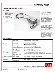
The following is a diagram of the major I/O components of the SolarTrak® Controller Board:<br />
Low<br />
Voltage<br />
Control<br />
12 VAC<br />
Power<br />
1 5 9 13<br />
Joystick<br />
Reset Button<br />
Toggle Switches<br />
UIM Header<br />
DB-9 Connector<br />
For PC Interface<br />
Powered by<br />
SolarTrak®<br />
Micro-Monitor<br />
© 2003 Enhancement Electronics, Inc.<br />
The SolarTrak® ST-2011-IAC Control Board<br />
Figure 1.<br />
Monitor Contrast<br />
Value Button<br />
Adjust Button<br />
Item Button<br />
4
Determining the Current Operational Mode<br />
The current operational mode is displayed on the micro-monitor (Figure 1) alternating<br />
once per second with the current time. This alternating status screen is the default display and<br />
implicitly indicates that the SolarTrak® Controller is functioning normally in one mode or<br />
another. Other display screens are available containing status or configuration data that can be<br />
viewed by pressing the Item Button, and when applicable, edited with the Adjust Button and<br />
Value Button. The display will return to the default display screen after one minute of idleness<br />
except while in the Adjust mode. Please see section on Displaying and Editing Parameters.<br />
Operational Modes<br />
- Tracking Mode: All toggle switches to LEFT (Joystick Inoperative)<br />
System goes through standard tracking scenario: Track during the daytime and assume<br />
a programmable Night Stow position while the Sun is below the horizon.<br />
- BackTracking Mode: Indicates direct tracking will produce shading.<br />
- Night STOW: Normal tracking Function for standard overnight position.<br />
- Emergency STOW: Bottom switch (STOW) to RIGHT (all others LEFT)<br />
Array moves to level (facing up) position.<br />
- <strong>Manual</strong> Mode: Top switch (MANUAL) to RIGHT (Overrides STOW and<br />
tracking). All motion other than Joystick input is prevented.<br />
<strong>Manual</strong> Control Mode - The manual control mode is an override to all motion functions of<br />
the controller. It is used when the array motion must be halted for safety while maintenance is<br />
performed or when the array must be moved to some unusual position.<br />
<strong>Manual</strong> mode is turned on using the MANUAL toggle switch at the lower left of the controller<br />
board under the joystick. The <strong>Manual</strong> switch is at the top of the red and white switch block.<br />
OFF<br />
ON<br />
<strong>Manual</strong> Mode<br />
Joystick Toggle Enable<br />
Emergency Stow Level Mode<br />
Figure 2.<br />
© 2003 Enhancement Electronics, Inc. 5
Joystick Operation – <strong>Manual</strong> Mode – SolarTrak facing north, operator facing south:<br />
EAST LEFT<br />
RIGHT WEST<br />
- With MANUAL switch only ON, joystick runs motor only while held and only when<br />
six seconds have passed since the last joystick input. The delay prevents ‘pounding’ the<br />
systems, mechanical and electronic.<br />
- With ‘Opt 1’ switch (second from top) as well as MANUAL, Touch and release to<br />
toggle ON then touch joystick in any direction to turn OFF. Toggle activation may be<br />
delayed by 6-second delay function but cut-off in immediate. If toggle fails to catch,<br />
press the joystick down (towards the bottom of the box) and release, wait the six seconds<br />
then try left or right again.<br />
The Controller enclosure is always to be mounted facing to the NORTH, to minimize<br />
direct sun and heat build-up in the Controller enclosure. While performing any Controller<br />
calibration or troubleshooting operation, the operator will therefore always be facing SOUTH<br />
while looking into the controller enclosure.<br />
Once MANUAL mode has been activated, the joystick may be used to move the array.<br />
Pushing the joystick toward the EAST (toward the LEFT side of the Controller board) will<br />
always move the array to point further to the EAST. Pushing the joystick toward the WEST<br />
(toward the RIGHT side of the Controller board) will always move the array to point further to<br />
the WEST.<br />
To EXTEND the screw, push the joystick TOWARD the side of the array where the<br />
screwjack is mounted or AWAY to RETRACT it.<br />
If the direction of travel of the array or the drive screw does not coincide with that<br />
described above, the Controller must be reconfigured, possibly including wiring changes. Until<br />
the Controller configuration has been performed, the array should remain in the horizontal<br />
position, with the power OFF.<br />
*** NOTE: The <strong>Manual</strong> switch should always be ON and<br />
the FINGER GUARD in place when powering-up the controller<br />
to prevent unexpected motion of the array or electric shock.<br />
Emergency Stow Mode - Emergency stow mode is used to manually interrupt tracking and<br />
move the array to a pre-defined position, typically where wind resistance is minimized and the<br />
array can be left parked without incurring damage. The Emergency stow switch is at the bottom<br />
of the toggle switch bank.<br />
© 2003 Enhancement Electronics, Inc. 6
Installation and Check-out Instructions<br />
*** WARNING ***<br />
This device operates on 208 VAC (with spikes to 600 VAC), develops<br />
over 10,000 pounds of force and 30,000 foot-pounds of torque.<br />
Installation, operation and maintenance by unqualified,<br />
inexperienced or inattentive individuals could result in bodily harm<br />
by dismemberment or electrocution, possibly resulting in death.<br />
Use CAUTION at all times while wotking with this machinery.<br />
Do not remove Finger Guard while power is ON!!<br />
Do not use fingers, screwdrivers or other tools to check or<br />
modify controller wiring while power is ON!!!<br />
Troubleshooting should be coordinated with<br />
Powerlight Corp. or EEInc.<br />
BE CAREFUL!!<br />
Enhancement Electronics, Inc. will not accept responsibility for<br />
accidents or damage resulting from ignorance, inattention or<br />
unwillingness to excercise appropriate caution while working with<br />
this machinery or failure to follow these instructions including failure<br />
to supervise motion tests prior to completion of installation and<br />
certification for unattended operation.<br />
© 2003 Enhancement Electronics, Inc. 7
Component Layout<br />
Powertracker – Single-Axis in NEMA 4X J-Box<br />
Single-Phase Power Option<br />
6<br />
1 14<br />
Controller Box<br />
½ hp<br />
AC Motor<br />
1<br />
Terminal Block<br />
1 13<br />
2A ¼A 10A<br />
Limit Switch Enclosure<br />
Limit Switch<br />
Potentiometer<br />
Figure 3.<br />
2 3 4 5 7 8<br />
Single-Phase Connections:<br />
1. Potentiometer Conduit – SolarTrak® Terminal #<br />
Black – Ground 1<br />
Red – +5V 3<br />
Green – Signal 14<br />
2. Limit Switch Cord -- > Connection 7 Term Block<br />
Red/White -- Extension Limit Sw. Pair 1,2<br />
Green/Black – Retraction Limit Sw. Pair 3,4<br />
3. Motor Power Cord -- > Connection 6<br />
Red – CCW Direction Lead 5<br />
Black – CW Direction Lead 6<br />
White – Common Lead 7<br />
Green – Chassis Ground 8<br />
© 2003 Enhancement Electronics, Inc. 8
4. Dual 208 VAC Power Source w/Ground<br />
Green – Earth Ground 9<br />
Black – 208 VAC phase pair 10 SolarTrak® Power<br />
White – 11<br />
Orange – 208 VAC phase pair 12 Motor Power<br />
Red – 13<br />
5. External Earth Ground Lug<br />
6. Motor Power Cord – Motor Lead #<br />
White – Common 1<br />
Black – Retract<br />
Red – Extend<br />
7. Limit Switch Cord<br />
Green/Black – Retraction Limit Switch<br />
Red/White – Extension Limit Switch<br />
8. Potentiometer Conduit<br />
Black – Retracted End Potentiometer<br />
Red – Extended End Potentiometer<br />
Green – Wiper<br />
Schematic: Standard 3-Wire <strong>Rev</strong>ersible Solid State Controller<br />
SolarTrak®<br />
Controller<br />
12 VAC IN<br />
S/S<br />
RLY<br />
Low Voltage Control<br />
Common<br />
Disconnect<br />
S/S<br />
RLY<br />
Potentiometer<br />
+5VDC<br />
Extend<br />
<strong>Actuator</strong><br />
Signal<br />
Ground<br />
S/S<br />
RLY<br />
Retract<br />
<strong>Actuator</strong><br />
Defeat<br />
Limit<br />
Switches<br />
Retract<br />
eeeeeeeeeeeeeee<br />
Potentiometer<br />
M<br />
Stepdown<br />
Transformer<br />
eeeee<br />
eeeee<br />
10 Amp Fast Blow<br />
Defeat Extend<br />
Common<br />
208 VAC Phase Leg Pair<br />
TVS<br />
208 VAC Phase Leg Pair<br />
1/4 Amp Fast Blow 2 Amp Fast Blow<br />
Earth Ground<br />
© 2003 Enhancement Electronics, Inc. 9
Powertracker – Single-Axis in NEMA 4X J-Box<br />
3-Phase Power Option<br />
15 22<br />
Controller Box<br />
1 14<br />
Controller Board<br />
AC Motor<br />
1b<br />
2b<br />
½ hp<br />
Solid-State<br />
Relay<br />
Board<br />
29 32<br />
Overload<br />
Relay<br />
23 25<br />
Fuses<br />
26 27<br />
28<br />
Limit Switch Potentiometer<br />
B A B A O<br />
M<br />
I<br />
X<br />
R<br />
Figure 4.<br />
1a 2a 3 4<br />
Limit Switch Enclosure<br />
3-Phase Connections:<br />
1. Potentiometer Conduit – 1a – SolarTrak® Terminal #<br />
Black – Ground 1<br />
Red – +5V 3<br />
Green – Signal 14<br />
2. Limit Switch Cord -- > Connection 1a<br />
Green/Black – Retraction Limit Sw. Pair 15, 16<br />
Red/White -- Extension Limit Sw. Pair 17, 18<br />
3. Motor Power Cord -- > Connection 2a<br />
Red – T3 29<br />
Black – T2 30<br />
White – T1 31<br />
Green – Chassis Ground 32<br />
© 2003 Enhancement Electronics, Inc. 10
4. 208 VAC Power Source w/Ground -- > Connection 3<br />
Red – 208 VAC L3 phase leg 23<br />
Black – 208 VAC L2 phase leg 24<br />
White – 208 VAC L1 phase leg 25<br />
Green – Earth Ground<br />
28 Ground Stud<br />
5. External Earth Ground Lug -- > Connection 4<br />
6. Motor Power Cord – Motor Lead # -- > Connection 2b<br />
White –<br />
T1<br />
Black –<br />
T2<br />
Red – T3<br />
Green –<br />
Ground Stud<br />
7. Limit Switch Cord -- > Connection 1b<br />
Green/Black – Retraction Limit Switch (R, B-Side)<br />
Red/White – Extension Limit Switch (X, B-Side)<br />
8. Potentiometer Conduit -- > Connection 1b<br />
Red – +5VDC Power - I(nner)<br />
Black – Ground - M(iddle)<br />
Green – Wiper - O(uter)<br />
9. Transient Voltage Suppressor (TVS) attaches between 25 & 26<br />
Joystick<br />
Switch Block<br />
Contrast<br />
Finger Guard<br />
Motor Output Landing<br />
Overload Relay Switch<br />
Power Input Landing<br />
TVS<br />
© 2003 Enhancement Electronics, Inc. 11
Schematic: 208VAC/3-Phase <strong>Rev</strong>ersible Solid-State Power Controller:<br />
Red<br />
Black<br />
White<br />
Solid-State AC<br />
H-Bridge<br />
<strong>Rev</strong>ersing<br />
Control<br />
Red<br />
Black<br />
White<br />
T3<br />
T2<br />
T1<br />
M<br />
Green<br />
Ground<br />
T4 T5 T6<br />
T7 T8 T9<br />
Defeat<br />
Limit<br />
Switches<br />
Extend<br />
Defeat<br />
Retract<br />
T1 T2 T3<br />
Low-Voltage Motor<br />
Shunt Configuration<br />
Extend<br />
<strong>Actuator</strong><br />
Retract<br />
<strong>Actuator</strong><br />
Low Voltage DC Control<br />
+5VDC<br />
Signal<br />
Ground<br />
Black<br />
Green<br />
Red<br />
SolarTrak® Controller<br />
eeeeeeeeeeeeeee<br />
12 VAC IN<br />
Potentiometer<br />
Overload<br />
Monitor<br />
T<br />
V<br />
S<br />
eeee<br />
eeee<br />
208/12VAC<br />
Stepdown<br />
Transformer<br />
208 VAC 3-Phase<br />
1/4 Amp Fast Blow<br />
2 Amp Fast Blow<br />
Fuse Block<br />
White<br />
Black<br />
Red<br />
Green<br />
L1<br />
L2<br />
L3<br />
Earth Ground<br />
© 2003 Enhancement Electronics, Inc. 12
Uncrating and Installation:<br />
Each shipping crate is marked with the orientation of the drive unit. East Mount means the drive<br />
unit is configured to be installed on the EAST end of the PV array it is driving, a West Mount<br />
goes on the WEST end.<br />
These instructions assume that the array is level prior to attaching the screwjack. The preconfigured<br />
Powertracker screwjack is shipped at the software LEVEL position with the screw<br />
manually retracted to fit in the box.<br />
Remove screws around the top/side of the crate lid. There is a hidden one at each end of the lid<br />
in the center crack. The lid comes off in one piece.<br />
Remove the screws from the cross braces over the motor/geardrive and control box. The one<br />
holding down the cover tube can stay.<br />
Lid Screws<br />
Braces<br />
Place the control box and coiled cable on top of the geardrive and screw then lift that end slightly<br />
while sliding the cover tube out from under its hold-down brace.<br />
Attach the geardrive to the pylon then mount the control box to its mounting plate.<br />
Clamp<br />
<strong>Drive</strong><br />
Pivot<br />
Flange<br />
Pylon<br />
<strong>Linear</strong> <strong>Actuator</strong><br />
Extension Length<br />
Flange Face<br />
Offset<br />
Base<br />
Pivot<br />
The two points of<br />
measurement for the<br />
<strong>Linear</strong> <strong>Actuator</strong><br />
Extension Length are<br />
the centerline of the<br />
clevis kingpin opening<br />
and the back face if the<br />
actuator mounting<br />
flange where it joins<br />
with the base pivot<br />
bracket.<br />
© 2003 Enhancement Electronics, Inc. 13
Loosen the clamp at the clevis end of the screw and boot.<br />
Unscrew the actuator screw until<br />
the measurement L is 41.75<br />
inches. All other things being<br />
correct, the clevis pin should fit<br />
right through the clevis and<br />
torque arm of the array. If the<br />
holes do not align<br />
it will be necessary to measure<br />
R1 and R2 then recompute the<br />
actuator parameters as defined in<br />
Appendix C. Lengthen or shorten<br />
the screw to fit with the torque<br />
tube and note the actual length.<br />
41.75”<br />
Pull the boot out to cover the metal stop at the clevis and reattach the clamp.<br />
Array Angle<br />
S = 0°<br />
R1<br />
R2<br />
L1<br />
Western Mount Position – View Facing South<br />
Level, Face-up Position<br />
© 2003 Enhancement Electronics, Inc. 14
Power Connection and Startup Sequence:<br />
1. Attach the three 208 VAC phase legs, WHITE to L1, Black to L2 and RED to L3.<br />
L1, L2, and L3 may be refered to as A, B, C or X, Y, Z or even T1, T2 and T3.<br />
The official 3-phase polarity is CBA. GREEN is Earth Ground/Chassis. The unit is<br />
shipped with a five-foot, 4-conductor, 12-gauge power pigtail.<br />
2. Just below the Joystick on left of SolarTrak® board, verify the top toggle switch is<br />
flipped to the RIGHT – <strong>Manual</strong> ON.<br />
3. Power-up the 3-phase circuit. Turn ON the activation knob on the Overload Relay.<br />
ON is when the handle of the rotary switch is straight up and down. Turn the<br />
handle slowly to be certain that the relay latches on properly. The motor will jump<br />
slightly at power-on but will stop immediately as the computer takes control.<br />
4. Verify SolarTrak® display is alternating between MODE MANUAL and TIME.<br />
*** NOTE: The following test will assure proper polarity of the motor before full operation<br />
is initiated. It is important to carefully monitor the retraction/extension length during this<br />
process to avoid damage to parts of the actuator.<br />
At both ends of screw travel, there are both software limits of operation which have effect only<br />
in automatic tracking mode and hardware limit switches which are to prevent accidental overtravel<br />
when all else fails. The hardware limits, not reached during normal controller operation,<br />
are set just outside of the software limits, and would only be reached in <strong>Manual</strong> operation or in<br />
the event of controller failure. The hardware limit switches interrupt the power to the drive motor<br />
relays. The hardware retraction limit switch is set to interrupt power at 13.5 inches. The extend<br />
limit is at 67.5 inches. These values are measured from the mating side of the drive mounting<br />
flange to the center of the drive screw kingpin.<br />
IF THE POLARITY IS WRONG, THE LIMIT SWITCHES DON’T WORK RIGHT!!!<br />
1. Using the Joystick (<strong>Manual</strong> ON without the ‘Latch function’), run the actuator in<br />
the Retract direction. (See page 6: Joystick RIGHT for drives on array EAST side; Joystick<br />
LEFT for drives on array WEST side.) If the screw extends instead of retracting, the polarity<br />
must be reversed. Assuming the declared color code is correct, this should be done at the 3-phase<br />
source by swaping the L2 and L3 legs.<br />
2. Once the polarity has been verified, the unit should be run in retract until it stops at<br />
the 13.5-inch hardware limit. If it does not stop before a minimum of 13.25 inches, it MUST be<br />
turned off before the actuator reaches 13 inches. If it does not turn off in time on its own,<br />
terminate the Installation Procedure immediately, leave the unit with <strong>Manual</strong> mode ON, and turn<br />
power off. The limit switch will need to be reset to conformity but there may be other<br />
considerations as well. Contact EEInc for further instructions, 505-281-0399.<br />
© 2003 Enhancement Electronics, Inc. 15
3. If the unit successfully stops at the 13.5-inch limit, switch the <strong>Manual</strong> toggle OFF,<br />
and switch the Emergency Stow toggle (bottom one) ON. After a brief delay, the unit should<br />
begin to extend the screw, eventually reaching and automatically stopping at a screw extension<br />
that corresponds to a horizontal array position, at a distance of about 41” from the screw pin to<br />
the mating side of the drive mounting flange surface. It will probably stop one or two counts<br />
(~1/2”) from exactly level. Check the Ax1 Count screen using the ITEM button to verify that the<br />
count is ~121. If the unit does not extend or stop at the horizontal array position, terminate the<br />
Installation Procedure, switch the unit to <strong>Manual</strong> ON, and turn power off. Contact EEI for further<br />
troubleshooting instructions, 505-281-0399.<br />
4. If the unit successfully stops at the horizontal array position, switch the <strong>Manual</strong><br />
toggle ON and switch the Emergency Stow toggle OFF. Using the Joystick, move the array to<br />
exactly level using some type of levelling device. Go to the ‘Set Level Offset’ screen, Press the<br />
Adjust button to display ‘Level Array’ (it’s already level) so then push and hold the VALUE<br />
button until the display returns to the Time/Mode heartbeat.<br />
5. Leave the unit in <strong>Manual</strong> Mode and continue extending the drive screw (you may<br />
want to use the Joystick “Latch” function at this point) until the screw reaches the fully-extended<br />
hardware limit, at a distance of about 67.5”. During this process, which will take 30-40 minutes,<br />
carefully monitor the progress of the screw, periodically checking the inches of screw extension.<br />
If the unit does not stop at the fully-extended hardware limit before it reaches 68”, terminate the<br />
Installation Procedure, leave the unit in <strong>Manual</strong> ON, and turn power off. Contact EEInc for<br />
further troubleshooting instructions, 505-281-0399.<br />
6. If the unit successfully stops at the fully extended hardware limit, switch the<br />
<strong>Manual</strong> toggle OFF, and switch the Emergency Stow toggle ON. After a brief delay, the unit<br />
should begin to retract the screw, eventually reaching and automatically stopping at a screw<br />
extension that corresponds to a horizontal array position, at a distance of about 45” from the<br />
screw pin to the mating side of the drive mounting flange surface. If the unit does not retract or<br />
stop at a horizontal array position, terminate the Installation Procedure, switch the unit to <strong>Manual</strong><br />
ON, and turn power off to the controller and drive motor. Contact EEI immediately for further<br />
instructions, 505-281-0399.<br />
If Step 6 is successful, the Installation and Check-Out Procedures have been successfully<br />
completed and the array will be ready to go into automatic tracking mode after the time, date,<br />
latitude, longitude and time zone have been checked.<br />
© 2003 Enhancement Electronics, Inc. 16
Display/Edit Parameters on SolarTrak® Controller Board<br />
Displaying Parameters with LCD Micro-Monitor<br />
The LCD Micro-Monitor allows display of a limited combination of calibration<br />
parameters and status values. It may be necessary to adjust the contrast using the thumb-pot just<br />
above the LCD. (See Figure 1). The standard display shows the current Time alternating with the<br />
current controller Mode. The three pushbuttons just below the monitor are, from left to right,<br />
ITEM, ADJUST and VALUE.<br />
The mode will be one of the following:<br />
1. Tracking Array is tracking normally<br />
2. Night Stow Array is parked for the night (will wake in morning)<br />
3. Emergency Stow Array is parked manually<br />
4. <strong>Manual</strong> Array is in <strong>Manual</strong> Mode<br />
There are several parameters and status values that may be displayed on the micromonitor<br />
screen. The following values are accessible:<br />
1. Time/Mode Local 24 Hr. Standard, NEVER Daylight Savings<br />
2. Date Year 2000 compliant<br />
3. Turncount Potentiometer reading (0 – 255)<br />
4. Temperature Use ‘VALUE’ to toggle between C & F<br />
5. Set Level Offset Calibration Command Function<br />
6. Seconds/Day Clock Correction each day<br />
7. Seconds/Week Clock correction once per week<br />
8. Latitude + Northern Hemisphere, - Southern (+/- 90 degrees)<br />
9. Longitude 0 = Greenwich, UK (Range 0 – 360 degrees West)<br />
10. Time Zone 0 = Greenwich, 5 = East Coast, 8 = West<br />
11. West Error<br />
12. BackTracking Use ‘VALUE’ to toggle to Width/Spacing Ratio<br />
13. Version Version Series and Date<br />
These values may be displayed, one at a time, by pressing the ITEM button, located just<br />
above the monitor. (See Figure 1). Due to space limitations on the screen, the above item<br />
descriptions will most often be abbreviated. The buttons are scanned once per second so it may<br />
take a moment to see the response. The button should be held down until it registers. The button<br />
will repeat its function once per second as long as it is held. After the last screen is displayed, it<br />
will start over with the Time. After approximately one minute of inattention, the display will<br />
revert back to alternating between the Time and Mode.<br />
© 2003 Enhancement Electronics, Inc. 17
Editing Parameter Values: On-board LCD/Button I/O<br />
*** NOTE: It is strongly recommended that the array be placed in MANUAL mode prior<br />
to changing parameters to avoid jumps, spurts and wasted time.<br />
ADJUST MODE is indicated by a flashing cursor square on the screen. This must<br />
be turned OFF by pressing the ADJUST Button before the ITEM Button can be<br />
used to change screens again.<br />
To Modify a Parameter:<br />
- Select a parameter that needs to be changed using the ITEM Button.<br />
- The VALUE Button may be required to access a ‘second-screen’ value.<br />
- Press the ADJUST Button<br />
- Use the ITEM Button to move the cursor Right to the digit to be changed.<br />
(The cursor position will ‘wrap’ back to the center of the screen at the end)<br />
- Press the VALUE Button to increment the value or change the sign.<br />
. All values have bounds and will wrap automatically in most cases<br />
. In order to create a negative number from or through zero (the sign will go positive at zero),<br />
the number must be made non-zero before changing the sign to negative.<br />
- When all digits are changed, press the ADJUST Button to revert to the normal mode.<br />
© 2003 Enhancement Electronics, Inc. 18
Section 5. Calibration to Onsite As-Built Parameters<br />
In the extreme, the hardware limit switches on the screwjack may need adjustment to<br />
allow enough extension. Do not exceed the linear actuator operational extension limit.<br />
There is NO MORE ROOM at the fully retracted limit! Further retraction will crush<br />
the boot spacers. Instructions for adjusting the limit switches and the required hex Allen wrench<br />
can be found inside the cover plate of the limit switch enclosure. The switch with the RED wire<br />
and the RED hex adjuster are the extension pair. Green and green are the retract pair.<br />
Several software configuration parameters must be redefined if the as-built measurements<br />
are out-of-spec.<br />
1. The Level Reference Offset – Calibrate array to Level (Facing straight UP)<br />
2. The East and West software limits – Set mathematical limits inside actual hard limits<br />
3. The Night Stow position – Overnight ‘Sleep’ Position<br />
4. The Emergency Stow (Level) Position – Position to assume with Stow Switch ON<br />
5. The Screwjack Mount Geometry definitions – Coefficients for Law of Cosines<br />
The first two can be performed using the buttons and joystick on the SolarTrak®. The<br />
rest require either a User Interface Module (UIM)* or a PC Interface (PCI)* software hookup.<br />
Only small adjustments on the order of ½” to ¾” of extension should be made without changing<br />
all of the above parameters.<br />
It will first be necessary to record the turncount values where the new soft limits should<br />
be as well as the two stow positions. The turncounts are displayed on the third screen (right after<br />
the date).<br />
The new screwjack parameters can be computed from the equations in the screwjack<br />
appendix. Care must be taken in choosing signs and angle quadrants. Making the Law of Cosines<br />
work is not an exact science.<br />
Once all the new parameters have been determined they will need to be stored in the<br />
controller’s memory. To do so, use the following procedures.<br />
* Available separately from Enhancement Electronics, Inc. (505) 281-0399<br />
Set Level Offset<br />
1. Use the Item button to select the screen that displays ‘Set Level Offset’<br />
2. Press the Adjust button until the screen reads, ‘Position Array’<br />
3. The array is now in <strong>Manual</strong> Mode though it will not be displayed.<br />
4. Use the joystick on the controller board or the UIM to position the array level.<br />
5. Press and hold the Value button on the controller board until the display reverts<br />
back to the Time/Mode display screen.<br />
© 2003 Enhancement Electronics, Inc. 19
Set East and West software limits<br />
Position the array to each soft limit and record the turncount from the SolarTrak® screen<br />
(third screen right after the date). This should be at + and – 45 degrees (East and West,<br />
respectively), however, do not reduce the lower limit (Ax1 –Lmt) below the factory setting (18 -<br />
22).<br />
If you will be using the UIM to do screwjack parameters and such, these values can go in<br />
more easily when you do the rest or use the following steps on the SolarTrak®:<br />
1. Use the Item button on the controller board to scroll to the screen that displays<br />
‘Ax1 +Lmt 215’<br />
2. Press the Adjust button so the dark, blinking cursor appears.<br />
3. Change the number to the desired value.<br />
4. Press ADJUST to end first edit.<br />
5. Press VALUE to change screen to ‘Ax1 –Lmt 19’<br />
6. Press the Adjust button so the dark, blinking cursor appears.<br />
7. Change to desired value (>18).<br />
8. Press ADJUST to end edit.<br />
Set Limit, Stow and Geometry Parameters with UIM<br />
Compute the three screwjack parameters, C1, C2 and C3 from the equations in the<br />
screwjack appendix. R1 and R2 will be the values changing. R3 will remain zero since the screw<br />
goes directly through the base pivot. C1 must be chosen so that substitution of +45, 0 and –45 all<br />
produce the same result for C1 (Beta). In addition C2 will be negative for an East mount and<br />
positive for a West mount.<br />
Plug in the UIM to the Interface Header with the ribbon cable downward. The UIM<br />
display should show the Version date, if not, repeat the power cycle, it should show up on the<br />
second try, or press the reset button (on the left side under the joystick).<br />
You will be changing parameters directly in SolarTrak® memory so:<br />
1. Press the second white button (down arrow) until the display reads:<br />
Status Display_<br />
Parameter View/Set_<br />
With the cursor blinking at the last underscore.<br />
2. Press the third white button (Enter/Select). The display will read:<br />
Control Params_<br />
User Board Params_<br />
With the cursor at the end of the ‘Control’ line<br />
© 2003 Enhancement Electronics, Inc. 20
3. Press Enter/Select again. The display will read:<br />
Limit and Stow<br />
Parameters_<br />
This parameter set contains the + and – software limits and<br />
stow positions – change as necessary.<br />
4. Press Enter/Select again. The display will read:<br />
Ax1 +Limit Active Hi<br />
5. Press the down button until the display reads:<br />
Ax1 Night Stow Pos.<br />
+70<br />
6. Change the value according to the UIM instructions in the appendix.<br />
7. Press Down once more to display:<br />
Ax1 Emer. Stow Pos.<br />
+84<br />
8. Change the value.<br />
Setting the screwjack parameters:<br />
1. Press the fourth button (Prev. Menu) Display will read:<br />
Limit and Stow<br />
Parameters_<br />
2. Press the second button until the display reads:<br />
Site Parameters_<br />
<strong>Drive</strong> Parameters_<br />
With the cursor at the end of the ‘<strong>Drive</strong>’ line<br />
3. Press Enter/Select.<br />
Display will read: Ax1 Gear Ratio<br />
+3.789<br />
With the cursor over the ‘3’.<br />
© 2003 Enhancement Electronics, Inc. 21
4. Press the down button until the display reads:<br />
Ax1 Screwjk Param #1<br />
+56.66°<br />
6. Change the value according to the UIM instructions in the appendix.<br />
7. Press Down once more to display:<br />
Ax1 Screwjk Param #2<br />
+3663.0<br />
8. Change the value.<br />
9. Press Down once more to display:<br />
Ax1 Screwjk Param #3<br />
+3819.25<br />
10. Change the value.<br />
© 2003 Enhancement Electronics, Inc. 22
User Interface Module<br />
Section 1.<br />
Menu Structure<br />
User Interface<br />
24 April 1998<br />
Time View/Set_<br />
Control Board Clock<br />
User Board Clock<br />
Display/Edit Clock<br />
Set Control Clock to<br />
User-Board Clock_<br />
Status Display_<br />
Tracking Status<br />
Error Status<br />
Alignment Status<br />
Input Sensor Status<br />
Parameter View/Set_<br />
Limit & Stow Params<br />
Site Params<br />
<strong>Drive</strong> Params<br />
Reference Sensor<br />
Params_<br />
Alignment Parameters_<br />
Misc. Parameters_<br />
© 2003 Enhancement Electronics, Inc. 23
Section 2. Keypad Layout<br />
0 1 2 3<br />
UP - Display Last Item<br />
Move Cursor Left<br />
(Time Set Screen Only)<br />
4 5 6 7<br />
8 9 A B Enter<br />
DOWN -Display Next Item<br />
Move Cursor Right<br />
(Time Set Screen Only)<br />
C<br />
+ / -<br />
D<br />
.<br />
E<br />
Exp<br />
F<br />
space<br />
Prev.<br />
Menu<br />
Move Left or Right<br />
(In All Other Screens)<br />
Change<br />
Sign<br />
Decimal<br />
Point<br />
Base<br />
10<br />
Exponent<br />
Section 3. Basic Operation<br />
The typical scenarios for use of the UIM are to:<br />
1. Set the TIME<br />
2. Adjust the Focus<br />
3. Tweak a tracking parameter (very satisfying, you should try)<br />
In general one navigates to the appropriate screen through use of the Up and Down keys<br />
and the ENTER key. To move from the TOP to BOTTOM and back in a list of parameters or<br />
menu items, press the Up or Down key. When a screen (specific phrase) is displayed, if it leads<br />
to another group of screens (menu items, parameters, commands), pressing ENTER will place<br />
you at the top of the new list. To move BACKWARD through the menus press the PREV<br />
MENU key, it will return you to the entry that got you where you are.<br />
If the screen is a parameter, the value will be displayed along with its description. If the<br />
value is changed using the keypad, it will be changed in EEPROM, non-volatile, reprogrammable<br />
memory.<br />
After navigating to the correct screen, in both the Time/Date and Parameter View/Set<br />
sections, there is a choice to access either the User Interface memory, or the Controller memory.<br />
Beyond that choice, the screens will appear the same. In most screens, while editing quantities,<br />
© 2003 Enhancement Electronics, Inc. 24
pressing the A or B button moves the cursor Left or Right. The exception is in the Set Time/Date<br />
screens where, once the Edit mode is entered, the Up and Down buttons function as Left and<br />
Right, respectively.<br />
When changing the Time/Date, one enters the Edit mode by pressing, ‘ENTER’ The<br />
delimiters ( ‘:’ and ‘/’) will not be overwritten by keystrokes. The Date notation is MM/DD/YY<br />
and the Time, HH:MM:SS. Simply overwrite the current values with better ones and press<br />
ENTER again.<br />
An embedded function in the SolarTrak® Controller is to calibrate its clock crystal selfcorrection<br />
algorithm. This only occurs when the Controller time is set from the UIM time via the<br />
appropriate command. This is a specific function in the Time/Date menu. First set the User<br />
Interface time to atomic Solar (Standard) time using the Edit User Interface clock menu. Then<br />
back-up to the previous menu and select the item that sets the Controller clock to the User<br />
Interface clock. This function automatically computes the error in seconds per day and seconds<br />
per week since the last time this command was performed on a given Controller and adds it to<br />
any existing error correction.<br />
In the parameter lists, once a chosen quantity is displayed, to change the value, type in<br />
the new value over the old, placing at least one space (‘F’ key) after the new value, then press<br />
ENTER. In some screens, the first keystroke will make the blinking cursor appear if it was not<br />
already visible. After the ENTER key is pressed, a slight delay may occur then the screen will<br />
display the new value with the cursor at the beginning of the line and no residue from the<br />
previous screen. This signifies that the value has been stored. If, after entering a new value on the<br />
screen, the user chooses to cancel the input, pressing the Up or Down button clears the buffer<br />
then one can begin again by returning to the original selection and starting over.<br />
© 2003 Enhancement Electronics, Inc. 25
PC Interface Software<br />
Section 1.<br />
Menu Structure<br />
PC Interface<br />
Switchboard<br />
Main Control Panel<br />
Idle Level – F1 – F10<br />
Shift Level – F1 – F10<br />
Ctrl Level – F1 – F10<br />
Alt Level – F1 – F10<br />
/ CONFIGURE or /CFG<br />
Programmer’s<br />
Panel<br />
Idle Level – F1 – F10<br />
Shift Level – F1 – F10<br />
Ctrl Level – F1 – F10<br />
Alt Level – F1 – F10<br />
© 2003 Enhancement Electronics, Inc. 26
DOS Command Line Option Switches<br />
Standard Invocation:<br />
C:\SolarTrk\> STNG<br />
<br />
The following command line switches (preceded by a ‘/’, forward slash) allow special<br />
initialization options and the ability to work with stored data without being connected to a<br />
SolarTrak®. Template files and the Internal Template will be discussed in Section<br />
/Cn<br />
/Tfn<br />
/Ifn<br />
n = a COM port number, i.e. /c3 designates COM3 as the active port<br />
fn = filename of Template file ( .TPL), i.e. /tEAST01 will use EAST01.TPL<br />
This switch preloads EAST01.TPL but still contacts the SolarTrak®<br />
Same as /Tfn but goes directly to the internal template<br />
i.e. /iWEST01 loads and displays the data saved in WEST01.TPL without<br />
attempting contact with the SolarTrak®<br />
/M Monochrome screen operation (graphic plots will be hard to read)<br />
/Pn<br />
n = a PRINTER port number, i.e. /p2 designates LPT2 as the active printer.<br />
/Ffn fn = filename of PC Interface configuration file to use (default =<br />
ST_NET.CFG)<br />
Ex: /fNONET uses the file NONET.CFG<br />
/W Data from the on-board thermometer and the wind anemometer (if installed)<br />
will be collected and stored at 1-2 second intervals in daily files named<br />
WTyymmdd.DAT. Each file is approximately 2.5 Mb. File names change<br />
automatically at midnight.<br />
/Dn<br />
Position data (screw length, sun angle, etc.) from the on-board computations<br />
will be logged every ‘n’ minutes in a file named PDyymmdd.DAT.<br />
© 2003 Enhancement Electronics, Inc. 27
D: The SolarTrak® PCI Configuration File<br />
% This is a Remark<br />
/begin<br />
% A slash marks a keyword<br />
/network No % Yes % Declare Network or Not<br />
%<br />
% if network is yes, specify # of nodes and unit #'s<br />
% nodes nodes<br />
% names can be any number from 1 to 65535 ie: /unit 1 1<br />
% /unit 2 64231<br />
% Hex (0001 - FFFF) can also be used: /unit 1 0xC3E0<br />
% /unit 2 0xA2D2<br />
%<br />
/Calibrate ON<br />
/Troubleshooting ON<br />
/DaylightSavings OFF<br />
/end % Lets CONFIG routine end gracefully<br />
%<br />
The PCI takes direction from both the configuration file and the command line. The<br />
elements of the configuration file reflect things that change little if at all. Those on the command<br />
line are more apt to change from use to use.<br />
© 2003 Enhancement Electronics, Inc. 28
E: Setting up Batch File Execution<br />
Since typing all these things in every time is tedious, putting them is a ‘.BAT’ file is<br />
recommended. Type the following:<br />
C:\SOLARTRK\> EDIT ST.BAT<br />
You will get a blank screen with menus all around it. Basically you will want to include any<br />
standard switches such as /Cn or /M that you will need each time, and perhaps a default template<br />
file if you eventually find that handy. Then add the ‘%1 %2 %3’ to allow extra switches to be<br />
declared on the command line as necessary each time the program is run, i.e.<br />
ST will run the program with the standard switches as defined in the batch file lines below.<br />
ST /IWEST01 will override the /TEAST01 entry stored in this ST.BAT file and go directly<br />
to the internal template WEST01.TPL without attempting to contact the SolarTrak.<br />
Switches are interpreted in the order they appear on the command line and the last will<br />
always apply.<br />
Moving right along.... Type:<br />
@echo off<br />
c:<br />
cd \solartrk<br />
stn /c3 /tEAST01 /m %1 %2 %3<br />
Press Alt-F<br />
Menu)<br />
Press X<br />
Press Y<br />
Saving File)<br />
C:\SOLARTRK\> COPY ST.BAT ..<br />
(put in the one’s you really need)<br />
(displays dropdown File<br />
(initiates Exit)<br />
(answer ‘Yes’ to<br />
(Puts a copy in the root directory)<br />
Or copy ST.BAT to any directory you normally use for such things in the standard DOS system search path.<br />
© 2003 Enhancement Electronics, Inc. 29
B: PC Interface Basic Keyboard I/O Techniques<br />
Use of the keyboard in the PCI software is fairly well standardized. Each function key,<br />
F1 – F10, can be pressed by itself or with one of the three combo keys, Shift, Ctrl or Alt. The<br />
bottom two lines (of 25) on the screen are always devoted to the current function-key menu.<br />
While idle with no keys pressed, the menu will indicate which function keys are active in the set<br />
of F1 – F10 for the current screen. In general there are four menu levels on each of three<br />
command levels but not all are necessarily active. Pressing one of Shift, Ctrl or Alt will change<br />
the menu displayed on the bottom two lines and reveal any available commands on that menu<br />
level.<br />
The PC Interface Panels and Menus<br />
The Network Switchboard<br />
.<br />
| .<br />
\|/ .<br />
==== O ==== .<br />
/|\ .<br />
| .<br />
.<br />
.<br />
.<br />
.<br />
.<br />
.<br />
.<br />
.<br />
.<br />
.<br />
……………………..<br />
.==================================. .<br />
.=====================| Network Switchboard |=====================..<br />
| `==================================’ |.<br />
Call [ 00000] \ .<br />
.<br />
10:18:57 7/13/1999 .<br />
Search Option Menu .<br />
F1: HELP F2: Load Template F10: or any Key to Exit--------------------------_<br />
Connect a serial extension cable (specifically not a Null-Modem cable) to the portable’s<br />
male 9 pin comm port and the SolarTrak’s female 9 pin connector. The important pins are 2,3<br />
and 5. They must connect directly to their counterparts at the other end. A cable can be made<br />
from good quality telephone wire or shielded signal wire and can be as long as 100 feet and work<br />
perfectly.<br />
*** Warning: Do not leave cable attached to SolarTrak® or computer when not in use!<br />
The first screen in a non-networked system will be the ‘Network Switchboard’ screen. To<br />
continue, press ESC, if there is a single SolarTrak® attached, it will download the parameters<br />
and open the Main Control Panel, otherwise it will quit.<br />
© 2003 Enhancement Electronics, Inc. 30
INITIAL STARTUP:<br />
“Main Control Panel” - After the PC Interface program starts, you should see the screen<br />
shown below. Later as one enters different sections of the program, this title bar will change.<br />
The following instructions will reference the appropriate title bar for each set of instructions.<br />
.<br />
Screen Title<br />
Indicates direct<br />
communication<br />
with SolarTrak<br />
Unit 4<br />
.<br />
| .<br />
\|/ .<br />
==== O ==== .<br />
/|\ .<br />
| .<br />
.=== Sun Position Information ===. .<br />
| Zenith 19.24 | .<br />
| Azimuth 51.37 | .<br />
| Elevation 70.76 | .<br />
Spinning indicates active<br />
`================================’ communication .<br />
.<br />
.<br />
.==================================. .<br />
.=====================| Main Control Panel |=====================..<br />
| `==================================’ |.<br />
SolarTrak[00004] Sun Angle – Count \ Array Angle – Count Wind(Mph) 0.0 .<br />
<strong>Manual</strong> 54.56 1292 Axis 1 54.51 1291 Temp.(F) 91.4 .<br />
9:45:06 7/13/2001 82.12 522 Axis 2 82.17 522 Batt.(V) 13.8 .<br />
Array Control Menu .<br />
F1:HELP F2:STOW F3:TRACK F5:MANUAL F9:SET TIME F10:EXIT .<br />
Current<br />
SolarTrak<br />
Operational<br />
Status<br />
Function<br />
Key Menu<br />
Time and<br />
Date from<br />
SolarTrak<br />
Sun Position in<br />
Degrees and<br />
turncounts<br />
Spinner<br />
Actual Array<br />
Position<br />
.<br />
.<br />
.<br />
Please note the spinning indicator in the center of the 5 th line above the “Axis 1” label. Proper<br />
communication between the PC and the SolarTrak produces the effect of the ‘Spinner’ spinning<br />
clockwise, moving about one position (1/8 th turn) per second. The spinner must be spinning in<br />
order to enter commands to the program.<br />
There are two reasons why the ‘Spinner’ may spin rapidly instead of its normally slower rate.<br />
1: When the PC Interface is accessing the internal copy (called a Template and must be<br />
downloaded from the SolarTrak or Loaded from a file, see File Operations) the<br />
‘SolarTrak[00004]’ is replaced by ‘File[filename]’ and the spinner spins rapidly because there is<br />
no communication delay when accessing internal memory. ‘Filename’ will read ‘download’ if<br />
the template was just downloaded from the controller. Toggle back and forth between the<br />
SolarTrak and the internal template by pressing ‘T’ on the keyboard.<br />
© 2003 Enhancement Electronics, Inc. 31
2: There is a communication problem between the computer and the SolarTrak. Likely<br />
causes of communication problems include: computer serial port turned off, computer serial port<br />
is set to a comm port other than comm port 1 (the default value for the PC Interface program).<br />
If the communications between the computer and the SolarTrak are correctly set, the spinning<br />
indicator should step slowly from one position to the next. This indicates that the computer is<br />
polling the SolarTrak.<br />
If the spinner is not spinning there are two typical reasons.<br />
1: The communications have been interrupted on a working comm line, in which case the<br />
current operating status should read ‘Off-Line’.<br />
2: The program is waiting for user input to an activated command such as changing a<br />
parameter value.<br />
If the PC Interface software is incorrectly directed to a non-existent comm port it will get<br />
garbage in the comm port status and think there is always a new character to read and spin fast as<br />
a result. If it is directed to a comm port that exists but is not properly connected to the<br />
SolarTrak® it will never get a new character and not spin at all.<br />
Entering a Command<br />
To invoke a command, begin by pressing the forward slash ‘/’. The Command box will replace<br />
the standard sun position display.<br />
The available commands are (abbreviation):<br />
1: Configure (CFG) – Set geometric, mathematical and logical parameters for tracking.<br />
2: Calibrate (CAL) – Collect, reduce and display data and error function for tilted tower.<br />
3: Target (TGT) – Set beam target bearing for HelioTrak® Units<br />
.<br />
| .<br />
\|/ .<br />
==== O ==== .<br />
/|\ .<br />
Command Input Block<br />
| .<br />
.<br />
.<br />
.==================================. .<br />
| Enter Command:> CFG | .<br />
`==================================’ .<br />
.<br />
.<br />
.<br />
.<br />
.<br />
.==================================. .<br />
.=====================| Command Input |=====================..<br />
| `==================================’ |.<br />
SolarTrak[00004] Sun Angle – Count \ Array Angle – Count Wind(Mph) 0.0 .<br />
<strong>Manual</strong> 54.56 1292 Axis 1 54.51 1291 Temp.(F) 91.4 .<br />
9:45:06 7/13/2001 82.12 522 Axis 2 82.17 522 Batt.(V) 13.8 .<br />
Array Control Menu .<br />
F1:HELP F2:STOW F3:TRACK F5:MANUAL F9:SET TIME F10:EXIT .<br />
© 2003 Enhancement Electronics, Inc. 32
The Configure (CFG) Command:<br />
The CFG command will initially produce the following screen:<br />
.<br />
Ax1 Array Positn Cnt: 1291 | .<br />
Ax2 Array Positn Cnt: 522 \|/ .<br />
Latitude (-90 to 90): 35.0525 ==== O ==== .<br />
Longitude (0 to 360): 106.0055 /|\ .<br />
Time Zone (0 to 23) : 7 | .<br />
Clock Adjust:Sec/Day: -4 .<br />
Clock Adjust:Sec/Wk : -3 .<br />
Batt Charger State : off .<br />
Batt Stw A/D (0-255): 186 .<br />
Battery Conver Factr: 0.1175 .<br />
Battery Charger On : 240 .<br />
Battery Charge Limit: 245 .<br />
.<br />
.<br />
.<br />
.<br />
.==========================================. .<br />
.=============| SolarTrak Basic Configuration Parameters |=====================..<br />
| `==========================================’ |.<br />
SolarTrak[00004] Sun Angle – Count \ Array Angle – Count Wind(Mph) 0.0 .<br />
<strong>Manual</strong> 54.56 1292 Axis 1 54.51 1291 Temp.(F) 91.4 .<br />
9:45:06 7/13/2001 82.12 522 Axis 2 82.17 522 Batt.(V) 13.8 .<br />
Configuration Menu .<br />
F1:HELP F4:Set Screwjack F5:MANUAL F9:Set Time F10:Done .<br />
There are two avenues of approach to adjust things. Press a function key to execute an operation or input<br />
information directly into the SolarTrak® using the parameter tables displayed on the upper screen. There are<br />
several groups (screens) of adjustable parameters. They can be accessed using the PgUp and PgDn keys. To<br />
change a parameter, highlight the offending value using the UP and DOWN arrows then press ‘ENTER:<br />
.<br />
Ax1 Array Positn Cnt: 1291 | .<br />
Ax2 Array Positn Cnt: 522 \|/ .<br />
Latitude (-90 to 90): 35.0525 ==== O ==== .<br />
Longitude (0 to 360): 106.0055 /|\ .<br />
Time Zone (0 to 23) : 7 | .<br />
Clock Adjust:Sec/Day: -4 .<br />
Clock Adjust:Sec/Wk : -3 .<br />
Batt Charger State : off .<br />
Batt Stw A/D (0-255): 186 .<br />
Battery Conver Factr: 0.1175 .<br />
Battery Charger On : 240 .<br />
Battery Charge Limit: 245 .<br />
.<br />
.<br />
.<br />
Parameter Input Line Current Input Value Note that<br />
.<br />
spinner will<br />
.==========================================. .<br />
.=============| SolarTrak Basic Configuration Parameters |=====================..<br />
freeze while<br />
>> Longitude (0 to 360) [106.0055]: 85.0773 waiting for .<br />
SolarTrak[00004] Sun Angle – Count \ Array Angle – Count Wind(Mph) 0.0 .<br />
<strong>Manual</strong> 54.56 1292 Axis 1 54.51 1291<br />
input<br />
Temp. (F) 91.4 .<br />
9:45:06 7/13/2001 82.12 522 Axis 2 82.17 522 Batt.(V) 13.8 .<br />
Array Control Menu .<br />
F1:HELP F4:Set Screwjack F5:MANUAL F9:Set Time F10:Done .<br />
Press ENTER to keep the current value or enter a new value then press ENTER. To TOGGLE<br />
a value ON or OFF (or whatever binary function), press ENTER then the SPACE BAR.<br />
© 2003 Enhancement Electronics, Inc. 33
PC Interface Software<br />
for the<br />
SolarTrak® Tracking<br />
Controller<br />
Main Control<br />
Panel<br />
/CFG<br />
F1 – Help<br />
F4 – Set Screwjack Parameters<br />
F5 – <strong>Manual</strong> Control<br />
F9 – Set Time<br />
F10 (Esc) – Done<br />
F1 – Help<br />
F2 – Stow Array<br />
F3 – Standard Tracking<br />
F5 – <strong>Manual</strong> Control<br />
F9 – Set Time<br />
Alt-F1 – Help<br />
Alt-F2 – Load Template File<br />
Alt-F3 – Download SolarTrak Parameters<br />
Alt-F4 –Upload Template to SolarTrak<br />
Alt-F5 – Save Template File<br />
Alt-F6 – Print Current Parameter Table<br />
F10 (Esc) – Exit PC Interface<br />
F1 – Help<br />
F2 –Take Tracking Error Data<br />
F3 – Calculate Error Function<br />
F4 – Plot Tracking Error Data<br />
F5 – <strong>Manual</strong> Control<br />
F9 – Set Time<br />
F10 (Esc) – Done<br />
Ctrl-F1 – Help<br />
Ctrl-F3 – Initialize Data File<br />
/CAL<br />
Ctrl-F5 – Upload Error Function Parameters<br />
Ctrl-F7 – Perform Reference Check<br />
/TGT<br />
F1 – Help<br />
F2 – Set Target Bearing Angle<br />
F6 – Delta / 10<br />
F7 – Delta * 10<br />
F9 – Set Time<br />
F10 (Esc) – Done<br />
© 2003 Enhancement Electronics, Inc. 34
Parameter Tables:<br />
Once in either the configuration or calibration menu, there are several groups of parameters that<br />
can be displayed on the screen by using the PgUp and PgDn keys. They are:<br />
Basic Configuration Parameters - Common Setup Values<br />
Useful Calibration Parameters - Status and Adjustment Parameters<br />
Limit and Stow Parameters - Software Limits and Stow Conditions<br />
Site Parameters<br />
- Site and Array <strong>General</strong> Description<br />
<strong>Drive</strong> Parameters<br />
- Geometric Descriptive Parameters<br />
Reference Sensor Parameters - Reference Check Conditions and Offsets<br />
Misalignment Parameters - Tower Misalignment Error Correction Function<br />
Miscellaneous Parameters - Unit #, Battery Charge Parameters and more…<br />
Tracking Status<br />
- Stow status, current Sun Values, Array Position<br />
Toggle Switch Settings<br />
- Access to keyboard control, on-board switch status<br />
Thermal Clock Correction Values - Data on thermal clock correction function<br />
OUCH Circuit Control<br />
- Control of Optional OUCH (defocussing) function<br />
© 2003 Enhancement Electronics, Inc. 35
Section 3. The Programmer’s Panel<br />
The programmer’s panel can be reached by entering the command /TROUBLE<br />
from the Main Control Panel. The first screen reached will be ‘SolarTrak Reference<br />
Sensor Parameters’. From there, the following menu tree applies:<br />
Main Control Panel<br />
/TROUBLE<br />
Programmer’s<br />
Panel<br />
Status: Idle Level<br />
F2 – Tracking Status<br />
F3 – Error Conditions<br />
F5 – Input Switch Status<br />
F6 – Print Current Table<br />
F9 – Set Controller Time<br />
Parameters: Shift Level<br />
F2 – Limit and Stow Parameters<br />
F3 – Site Parameters<br />
F4 – <strong>Drive</strong> Parameters<br />
F5 – Reference Sensor Parameters<br />
F6 – Misalignment Parameters<br />
F7 – Miscellaneous Parameters<br />
Miscellaneous: Ctrl Level<br />
F2 – <strong>Manual</strong> Mode Toggle<br />
F5 – Emergency Stow Toggle<br />
F6 – Print All Tables<br />
File Operations: Alt Level<br />
The Programmer’s Panel Screen<br />
F2 – Load Parameter File from Disk<br />
F3 – Download SolarTrak Parameters<br />
F4 – Upload Parameters to SolarTrak<br />
F5 – Save Parameter File to Disk<br />
F6 – Save Printable Parameter File<br />
© 2003 Enhancement Electronics, Inc. 36
.<br />
Ax1 Gear Ratio : 3.7800 Timed Motor-On Mode?: No .<br />
Ax1 Screwjk Param #1: 120.8222 Full-Deadband Mode? : Yes .<br />
Ax1 Screwjk Param #2: 3731.9041 Backtracking Mode? : Yes .<br />
Ax1 Screwjk Param #3: 3927.2490 Width/Spacing Ratio : 0.5000 .<br />
Ax2 Gear Ratio : 0.0000 Absolute Encoder? : Yes .<br />
Ax2 Screwjk Param #1: 0.0000 Ax1 +Joystick Mask : 0x10 .<br />
Ax2 Screwjk Param #2: 0.0000 Ax1 -Joystick Mask : 0x04 .<br />
Ax2 Screwjk Param #3: 0.0000 Ax2 +Joystick Mask : 0x20 .<br />
Ax1 Coast Counts : 1 Ax2 -Joystick Mask : 0x08 .<br />
Ax1 Time/Coast Swtch: 1 Mtr Stall Chk (Sec) : 60 .<br />
Ax1 Deadband Counts : 3 Motor Delay (Sec) : 4 .<br />
Ax2 Coast Counts : 0 Mtr-Turn Chk Intervl: 250 .<br />
Ax2 Time/Coast Swtch: 0 Trk Output Active Hi: Yes .<br />
Ax2 Deadband Counts : 0 .<br />
.<br />
.<br />
.==================================. .<br />
.=====================| SolarTrak <strong>Drive</strong> Parameters |=====================..<br />
| `==================================’ |.<br />
SolarTrak[00004] Sun Angle – Count \ Array Angle – Count Wind(Mph) 0.0 .<br />
<strong>Manual</strong> 54.56 1292 Axis 1 54.51 1291 Temp.(F) 91.4 .<br />
9:45:06 7/13/1999 Batt.(V) 13.8 .<br />
F1 | F2 | F3 |-----| F5 | F6 |-----|-----| F9 | F10 .<br />
HELP | TRACKING | ERROR |-----| SWITCH | PRINT |-----|-----| SET TIME | DONE .<br />
To change screwjack parameters, press Shift-F4 to get to the <strong>Drive</strong> Parameters screen.<br />
Use the Up/Down arrows to highlight a value, press Enter to select for change. A prompt for new<br />
data will appear just below the screen title. Type in the new number, (the old one is in brackets)<br />
and press Enter again.<br />
Press Shift-F2 to change the software limits in the Limit and Stow Parameters screen.<br />
Press Shift-F3 to change the Latitude and Longitude in the Site Parameters screen.<br />
Press Shift-F7 to change the clock correction values in the Miscellaneous Parameters<br />
screen.<br />
© 2003 Enhancement Electronics, Inc. 37
Swapping or Installing the SolarTrak® Microcontroller Chip<br />
The most appropriate method to exchange the controller chip is to use a PLCC chip<br />
extractor. It uses little prongs extended into the slots at the lower-left and upper-right of the chip,<br />
hooks under the chip and lifts it out evenly and smoothly without tipping or cocking the chip in<br />
the socket which causes the pins to bind and bend. BAD!<br />
If one uses Great Caution!, there is an alternate method of extracting the chip. Use a<br />
small jeweler’s screwdriver to slip into one slot at a time. Gently pry the corner up only a<br />
fraction of the necessary amount to free it. Move the screwdriver to the other slot and repeat the<br />
gentle pry up. Use your fingers to keep the chip level on the other two corners without slots. Two<br />
or three complete repetitions should do it.<br />
When inserting the new chip, there is a corner shaved off that goes on the upper-left of<br />
the socket, near the RESET button. Settle the chip into the socket gently and verify all the pins<br />
line up and the chip is square with the socket. Gently rocking the chip with a couple of fingers<br />
will produce a ‘floating’ effect on the pins indicating a good placement, then push the chip<br />
straight into the socket, again keeping the chip level with several fingers.<br />
Verify that the <strong>Manual</strong> switch is flipped to the right, power up and check for proper<br />
operation.<br />
© 2003 Enhancement Electronics, Inc. 38
Moving Parameters between SolarTrak’s<br />
When adding new trackers or creating a backup tracking system, it can be tedious to<br />
transfer all the parameters unique to your system. Using the download and upload functions as a<br />
transfer mechanism is the easiest and least error-prone method.<br />
Step 1:<br />
Menu)<br />
Step 2:<br />
Step 3:<br />
Step 4:<br />
Step 5:<br />
Download the template from the SolarTrak being duplicated. (Alt-F3 from Main<br />
Save template on disk in swap file. (Alt-F5)<br />
Press ESC to enter a filename directly<br />
Type: SWAP then press the ‘Enter’ key<br />
Either power down the SolarTrak and swap the controller chip then power back up...<br />
or<br />
Connect the PC to the new SolarTrak.<br />
Load the swap file SWAP.TPL, just to make sure. (Alt-F2)<br />
Press ESC toenter file name directly.<br />
Type: SWAP then press ‘Enter’ key<br />
Upload swap data to New or Replacement SolarTrak (Alt-F4)<br />
When this step completes, it will ask if you want to remain in <strong>Manual</strong> Mode where it was<br />
put to inhibit motion during the upload. Press ‘N’.<br />
If one is cautious to keep the PC program running while changing chips or connections,<br />
Step 2 & Step 4 can be omitted. The internal data integrity is maintained once loaded as long as<br />
the PC interface software remains running so saving a swap file is just a precaution. The safest<br />
approach is to save the file and reload if you think something happened to the data. The internal<br />
data set is accessed by pressing ‘T’ on the keyboard to toggle back and forth. The Unit # changes<br />
to a file name designating the difference.<br />
© 2003 Enhancement Electronics, Inc. 39
Appendix C:<br />
screwJACK\\\\\\\\\\\\Parameter Computation<br />
Array Angle<br />
S = 0°<br />
R1<br />
R2<br />
L1<br />
Western Mount Position – View Facing South<br />
Level, Face-up Position<br />
East<br />
Array Angle<br />
S = +45°<br />
Tracking<br />
Axis<br />
Pivot<br />
<strong>Linear</strong> <strong>Actuator</strong><br />
Extension Length<br />
Flange Face<br />
Offset<br />
Torque<br />
Arm<br />
<strong>Drive</strong><br />
Pivot<br />
Flange<br />
L2<br />
Pylon<br />
Base<br />
Pivot<br />
Unit Retracted to Soft Limit, S = 45°<br />
© 2003 Enhancement Electronics, Inc. 40
Array Angle<br />
S = -45°<br />
West<br />
L3<br />
<strong>Linear</strong> <strong>Actuator</strong> at Full Extension to Soft Limit, S =-45°<br />
There are three screwjack parameters stored in the SolarTrak® in the ‘<strong>Drive</strong><br />
Parameters’ screen, SJP #1-3, computed from the quantities R1, R2, L1-3 defined<br />
above. Lengths are in inches.<br />
The Law of Cosines is applied to convert the requested angular position to a<br />
specific actuator extension. The fundamental equation relating the actuator length and<br />
array angle is:<br />
(1) L = √ R1^2 + R2^2– 2 * R1 * R2 * COS(S + β)<br />
Where L is the length of the actuator, S is the requested array angle and β is an angular<br />
offset based on the relative positions of R1 and R2 when the array is facing straight up<br />
(S = 0). Since some of the computations for these terms need only be performed once,<br />
the parameters are stored as pre-combined coefficients producing the equivalent<br />
equation (2).<br />
SJP #2 = (+/-) 2 * R1 * R2<br />
SJP #3 = R1^2 + R2^2<br />
(+West Mount, -East)<br />
(2) L = √ SJP#3 + SJP#2 * COS(S + β)<br />
(3) β = ACOS {(L^2– SJP#3)/ SJP#2} – S SJP #1 = β<br />
Equation (1) above is used for converting a specific Sun angle to a specific screwjack<br />
extension point. Equation 3 should be used to determine β for L equals each of the measurable<br />
quantities L1 (S = 0), L2 (S = 45, in radians) and L3 (S = -45). The result found for β should be<br />
the same in each case.<br />
© 2003 Enhancement Electronics, Inc. 41