PSTC - Linear Actuator Drive - General Manual Rev 2.pdf
PSTC - Linear Actuator Drive - General Manual Rev 2.pdf
PSTC - Linear Actuator Drive - General Manual Rev 2.pdf

You also want an ePaper? Increase the reach of your titles
YUMPU automatically turns print PDFs into web optimized ePapers that Google loves.
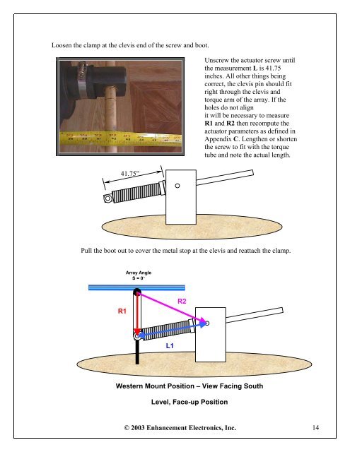
Loosen the clamp at the clevis end of the screw and boot.<br />
Unscrew the actuator screw until<br />
the measurement L is 41.75<br />
inches. All other things being<br />
correct, the clevis pin should fit<br />
right through the clevis and<br />
torque arm of the array. If the<br />
holes do not align<br />
it will be necessary to measure<br />
R1 and R2 then recompute the<br />
actuator parameters as defined in<br />
Appendix C. Lengthen or shorten<br />
the screw to fit with the torque<br />
tube and note the actual length.<br />
41.75”<br />
Pull the boot out to cover the metal stop at the clevis and reattach the clamp.<br />
Array Angle<br />
S = 0°<br />
R1<br />
R2<br />
L1<br />
Western Mount Position – View Facing South<br />
Level, Face-up Position<br />
© 2003 Enhancement Electronics, Inc. 14