CHAPTER 22 MODELING AND UNDERSTANDING BLEVEs
CHAPTER 22 MODELING AND UNDERSTANDING BLEVEs
CHAPTER 22 MODELING AND UNDERSTANDING BLEVEs

You also want an ePaper? Increase the reach of your titles
YUMPU automatically turns print PDFs into web optimized ePapers that Google loves.
<strong>22</strong>.1 INTRODUCTION<br />
<strong>CHAPTER</strong> <strong>22</strong><br />
<strong>MODELING</strong> <strong>AND</strong><br />
UNDERST<strong>AND</strong>ING <strong>BLEVEs</strong><br />
J. Casal, J. Arnaldos, H. Montiel, E. Planas-Cuchi, and J. A. Vílchez<br />
Centre d’Estudis del Risc Tecnològic (CERTEC),<br />
Universitat Politècnica de Catalunya—Institut d’Estudis Catalans,<br />
Barcelona, Catalonia, Spain<br />
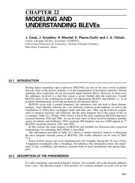
Boiling liquid expanding vapor explosions (<strong>BLEVEs</strong>) are one of the most severe accidents<br />
that can occur in the process industry or in the transportation of hazardous materials. Strictly<br />
speaking, these explosions do not necessarily imply thermal effects. However, in most cases<br />
the substance involved is a fuel that causes a severe fireball after the explosion. Usually<br />
BLEVE refers to the combination of these two phenomena, BLEVE and fireball, i.e., to an<br />
accident simultaneously involving mechanical and thermal effects.<br />
<strong>BLEVEs</strong> occur with a certain frequency: the substances that can lead to them (butane,<br />
propane, vinyl chloride, chlorine, etc.) are relatively common in the industry, as well as the<br />
installations in which they can happen (tanks and tank cars). They can have diverse origins,<br />
such as runaway reactions and collisions, but the most frequent one is the action of fire on<br />
a container. Table <strong>22</strong>.1 (Prugh, 1991) shows a list of the most significant <strong>BLEVEs</strong> that have<br />
occurred between 1926 and 1986. As can be seen, most of these involved fatalities. Another<br />
source (Londiche and Guillemet, 1991) mentions 900 fatalities and over 9,000 injured in 77<br />
<strong>BLEVEs</strong> occurring between 1941 and 1990.<br />
In this section, the main features of <strong>BLEVEs</strong> and fireballs are discussed and a practical<br />
methodology for estimating their effects is described.<br />
The information provided in Table <strong>22</strong>.1 allows a simple statistical analysis to determine<br />
the most frequent external causes of <strong>BLEVEs</strong>. The results obtained can be seen in Table<br />
<strong>22</strong>.2.<br />
Some of these causes can occur simultaneously (for example, among the 18 cases of fire,<br />
5 happened immediately after a derailing). Nevertheless, this information shows the importance<br />
of fire, overfilling, and runaway reactions both in fixed installations and during transport.<br />
<strong>22</strong>.2 DESCRIPTION OF THE PHENOMENON<br />
If a tank containing a pressurized liquid is heated—for example, due to the thermal radiation<br />
from a fire—the pressure inside it will increase. At a certain moment, its walls will not be<br />
<strong>22</strong>.1
<strong>22</strong>.2 <strong>CHAPTER</strong> TWENTY-TWO<br />
TABLE <strong>22</strong>.1 The Most Significant BLEVE Accidents from 1926 to 1986<br />
Date Place Cause Material Tons Fatalities<br />
12/13/1926 St. Auban, France Overfilling Chlorine 25 19<br />
5/28/1928 Hamburg, Germany Runaway reaction Phosgene 10 10<br />
5/10/1929 Syracuse, NY, U.S.A. Explosion (H 2) Chlorine 25 1<br />
12/24/1939 Zarnesti, Rumania Overfilling Chlorine 10 60<br />
7/29/1943 Ludwigshafen, Germany Overfilling Butadiene 16 57<br />
11/5/1947 Roemo, Finland Overfilling Chlorine 30 19<br />
7/28/1948 Ludwigshafen, Germany Overfilling Ethyl ester 33 209<br />
7/7/1951 Port Newark, NJ, U.S.A. Fire Propane 2,600 0<br />
4/4/1952 Walsum, Germany Overfilling Chlorine 15 7<br />
1/4/1954 Institute, WV, U.S.A. Runaway reaction Acrolein 20 0<br />
1/8/1957 Montreal, Quebec, Canada Fire Butane ? 1<br />
1958 Alma, MI, U.S.A. Overfilling Butane 55 1<br />
6/28/1959 Meldria, U.S.A. Derailing Propane 55 23<br />
8/18/1959 Kansas City, U.S.A. Fire Gasoline 20 5<br />
4/17/1962 Doe Run, MO, U.S.A. Runaway reaction Ethylene oxide 25 1<br />
1/4/1966 Feyzin, France Fire Propane 1,000 18<br />
1/1/1968 Donreith, U.S.A. Derailing (fire) Ethylene oxide 2 0<br />
8/21/1968 Lieven, France Mechanical Ammonia 20 5<br />
1/2/1969 Repcelak, Hungary Overfilling Carbon dioxide 35 9<br />
1/25/1969 Laurel, MS, U.S.A. Derailing (fire) Propane 65 2<br />
2/18/1969 Crete, NE, U.S.A. Derailing Ammonia 65 8<br />
4/29/1969 Cumming, IA, U.S.A. Derailing Ammonia ? ?<br />
9/11/1969 Glendora, CA, U.S.A. Fire Vinyl chloride 55 0<br />
6/21/1970 Crescent City, IL, U.S.A. Derailing (fire) Propane 275 0<br />
1/19/1970 Baton Rouge, LA, U.S.A. Overpressure Ethylene 4 0<br />
10/19/1971 Houston, TX, U.S.A. Derailing (fire) Vinyl chloride 50 1<br />
2/9/1972 Tewksbury, MA, U.S.A. Collision Propane 28 2<br />
3/30/1972 Rio de Janeiro, Brazil Fire Propane 1,000 37<br />
9/21/1972 Turnpike, NJ, U.S.A. Collision Propylene 18 2<br />
11/2/1972 San Antonio, TX, U.S.A. Corrosion Carbon dioxide 0.01 0<br />
7/5/1973 Kingman, AZ, U.S.A. Fire Propane 100 13<br />
1/11/1974 West St. Paul, MN, U.S.A. Fire Propane 27 4<br />
2/12/1974 Oneonta, NV, U.S.A. Derailing (fire) Propane 288 0<br />
7/29/1974 Pueblo, CO, U.S.A. Fire Propane 80 0<br />
4/29/1975 Eagle Pass, TX, U.S.A. Collision Propane 18 16<br />
12/14/1975 Niagara Falls, NY, U.S.A. Runaway reaction Chlorine 20 4<br />
5/11/1976 Houston, TX, U.S.A. Collision Ammonia 20 6<br />
8/31/1976 Gadsden, AL, U.S.A. Fire Gasoline 4 3<br />
1977 Cartagena, Colombia Overpressure Ammonia 7 30<br />
2/<strong>22</strong>/1978 Waverly, TN, U.S.A. Derailing Propane 45 12<br />
7/11/1978 Els Alfacs, Spain Dilatation/overpressure Propylene 23.6 216<br />
5/30/1978 Texas City, TX, U.S.A. Fire Butane 1,500 7<br />
8/30/1979 Good Hope, LA, U.S.A. Ship collision Butane 120 12<br />
8/1/1981 Montonas, Mexico Derailing Chlorine 110 29<br />
1/19/1982 Spencer, USA Overheating Water 0.3 7<br />
12/11/1982 Taft, LA, U.S.A. Runaway reaction Acrolein 250 0<br />
7/12/1983 Reserve, LA, U.S.A. Runaway reaction Chlorobutadiene 1 3<br />
10/4/1983 Houston, TX, U.S.A. Overfilling Methyl bromide 28 2<br />
11/19/1984 Mexico City, Mexico Fire Propane 3,000 500<br />
1/28/1986 Kennedy Space Center, FL, U.S.A. Fire Hydrogen 115 7<br />
Source: Prugh, 1991.
<strong>MODELING</strong> <strong>AND</strong> UNDERST<strong>AND</strong>ING <strong>BLEVEs</strong> <strong>22</strong>.3<br />
TABLE <strong>22</strong>.2 The Most Frequent External<br />
Causes of <strong>BLEVEs</strong><br />
Cause %<br />
Fire 26<br />
Derailing 20<br />
Overfilling 18<br />
Runaway reaction 12<br />
Collision 10<br />
Overpressure 6<br />
Other 8<br />
able to withstand the high stress and they will collapse (the steel typically used for the<br />
construction of LPG vessels may fail at pressures of about 15 atm, when the temperature of<br />
the walls reaches approximately 650�C). This is most likely to occur in the top section of<br />
the container, where the walls are not in contact with the liquid and therefore not cooled by<br />
it; the temperature of the walls will increase and their mechanical resistance will decrease<br />
(Birk, 1995). Instead, the wall in contact with the liquid will transfer heat to the liquid, thus<br />
maintaining a much lower temperature. If a safety valve opens, the boiling liquid will have<br />
a stronger cooling action due to the heat of evaporation.<br />
Upon failure, due to the instantaneous depressurization, the temperature of the liquid will<br />
be greater than that corresponding to the new pressure according to the saturation curve in<br />
the P-T diagram. In this unstable condition, it is called superheated liquid. Liquids normally<br />
can withstand a small amount of superheating, which in certain experimental conditions can<br />
be extended far above the atmospheric-pressure boiling point (Prugh, 1991). However, there<br />
is a limit to superheat, called the superheat temperature limit (different for each substance).<br />
Then, if the temperature of the liquid at the moment of depressurization is higher than the<br />
superheat temperature limit, a violent and instantaneous flash of a fraction of the liquid and<br />
a superheated liquid vapor explosion will take place; a biphasic liquid/vapor mixture will<br />
then be released. This phenomenon occurs in a very short time (1 ms). The significant<br />
increase in the liquid’s volume when it vaporizes—1,750 times in the case of water and 250<br />
times in the case of propane—plus the expansion of the previously existing vapor, will give<br />
rise to a strong pressure wave (explosion, bursting of the container) as well as to the breaking<br />
of the container into several pieces, which will be propelled considerable distances. Experimental<br />
work performed with small 1-l vessels (Mcdevitt et al., 1990) has shown that when<br />
there is a break in the vessel, the pressure drops slightly and then rises up to a maximum;<br />
the initial depressurization brings the fluid near the break to a superheated state, thus causing<br />
a local explosion.<br />
If the substance involved is not combustible, the pressure wave and the missiles will be<br />
the only effects of the explosion. This could happen if a steam boiler (water steam) exploded.<br />
If the substance is a fuel, however, as often happens in the process industry (for example,<br />
liquefied petroleum gas, such as ethylene or propane), the mixture of liquid/gas released by<br />
the explosion will probably ignite, giving rise to a fireball of approximately hemispherical<br />
shape, initially at ground level. The effect of the thermal radiation in this first stage, which<br />
is usually only a couple of seconds, is very important. The whole mass of fuel can burn<br />
only at its periphery because there is no air inside the mass (the mixture is outside the<br />
flammability limits).<br />
In fact, not all the fuel initially contained in the tank is involved in this fire. Some of the<br />
fuel is entrained in the wake formed by the flying fragments. In one case (Mexico City,<br />
1984), it has been suggested that a portion of the liquid was thrown significant distances<br />
without being ignited, which caused local fires (this effect has not been mentioned in any
<strong>22</strong>.4 <strong>CHAPTER</strong> TWENTY-TWO<br />
other case). This decreases the amount of fuel contained in the fireball and also affects its<br />
dimensions and the duration of the fire.<br />
Later on, the turbulence of the fire entrains air into the fireball. Simultaneously, the<br />
thermal radiation vaporizes the liquid droplets and heats the mixture. As a result of these<br />
processes, the whole mass turbulently increases in volume, evolving towards an approximately<br />
spherical shape that rises, leaving a wake of variable diameter. Such fireballs can be<br />
very large, causing a very strong thermal radiation. The combined action of BLEVE and<br />
fireball can be summarized therefore in the following effects:<br />
• Thermal radiation<br />
• Pressure wave<br />
• Flying fragments<br />
The mode in which these effects actuate varies: punctual or directional in the case of<br />
projectiles, and zonal—covering a given surface—in the case of thermal radiation and blast.<br />
It is worth noting that it is practically impossible to establish the exact instant at which<br />
the explosion will take place. Twenty years ago it was believed that once the emergency<br />
started—for example, from the instant in which fire started to impinge on a container—there<br />
was a certain time available before the explosion. It therefore seemed that diverse measures<br />
could be taken to prevent the explosion (for example, firefighters could refrigerate the tank<br />
with hoses). However, as more information was gathered on actual accidents, it became<br />
evident that this time could be extraordinarily short; in the San Juan Ixhuatepec accident in<br />
Mexico City (Pietersen and Cendejas, 1985), the time elapsed between the first explosion<br />
(which caused the fire) and the first BLEVE was only 69 seconds. The various stages of a<br />
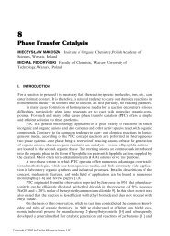
BLEVE/fireball are shown in Fig. <strong>22</strong>.1.<br />
The instant at which a BLEVE can occur in a tank exposed to fire depends on the<br />
following factors:<br />
1. Thermal flux from the fire, which will be a function of the distance from the flame to<br />
the tank and will depend on whether there is flame impingement and the type of flame<br />
(pool fire, torching, etc.)<br />
2. Diameter of the tank<br />
3. Tank fill level<br />
4. Release capacity of safety valves<br />
5. Existence of a layer (with a certain thickness) of isolating material (passive protection)<br />
Theoretically, an insulated container should resist the effect of the flames from a poolfire<br />
(thermal flux of approximately 100 kW � m �2 ) for two hours. In the case of a jet fire,<br />
the thermal flux increases significantly (up to 350 kW � m �2 ). In these conditions, some<br />
<strong>BLEVEs</strong> have occurred in the first minutes. For the development of this type of accident,<br />
the following times have been suggested (Nazario, 1988): flame impingement from a jet fire,<br />
5 minutes; flame impingement with turbulent flames, 30 minutes (this value agrees with that<br />
proposed by ASTM (ASTM, 1983), 20 to 30 minutes). Although this time can vary with<br />
the features of the installation (insulating layer, cooling devices), it is evident that other<br />
factors can decrease it significantly (partial destruction due to impacts or pressure wave, for<br />
example). The most cautious practice, therefore, is to take into account that the explosion<br />
can occur at any moment from the beginning of the emergency. The exclusion area should<br />
therefore be rapidly evacuated.
FIGURE <strong>22</strong>.1 BLEVE-fireball: loss of containment, fire, tank heating, bursting and evolution of fireball.<br />
<strong>22</strong>.5
<strong>22</strong>.6 <strong>CHAPTER</strong> TWENTY-TWO<br />
<strong>22</strong>.3 CONDITIONS REQUIRED FOR A BLEVE TO OCCUR<br />
<strong>22</strong>.3.1 Superheating and Depressurization<br />
While the explosion of a tank containing a pressurized flammable liquid will almost always<br />
lead to a fireball, the explosion cannot always be considered strictly a BLEVE. To qualify<br />
as this type of explosion, the following conditions must be met (Reid, 1979; Mañas, 1984;<br />
Bestratén and Turmo, 1991a; Birk, 1995):<br />
• Significant superheating of the liquid. Most liquefied gases under fire attack (LPG, ammonia,<br />
chlorine) fulfil this condition; it can also be fulfilled by other liquids contained in<br />
closed containers that undergo anomalous heating, for example due to a fire; and, as stated<br />
before, water can also be at this condition upon instantaneous depressurization.<br />
• Instantaneous depressurization. This phenomenon is usually related to the type of failure<br />
of the vessel. The sudden pressure drop in the container upon failure causes the liquid<br />
superheat. If the liquid superheat is significant, the flashing may be explosive.<br />
When these two conditions are met, a practically instantaneous evaporation of the contents<br />
takes place, with the formation of a large number of boiling nuclei in all the liquid mass<br />
(homogeneous nucleation). In these conditions, the velocity at which the volume increases<br />
is extraordinary and the explosion is therefore very violent. Strictly speaking, this is the<br />
phenomenon associated with the BLEVE explosion.<br />
<strong>22</strong>.3.2 Temperature and Superheating Limit Locus<br />
Diverse authors have suggested procedures to establish the superheat temperature limit and<br />
the superheating limit locus that determine, for each substance, the conditions under which<br />
a BLEVE can occur. Reid (1976, 1979) made a significant contribution to this field.<br />
The theoretical superheating limiting conditions at which spontaneous homogeneous nucleation<br />
will exist in all the liquid mass can be established from the tangent line to the vapor<br />
pressure-temperature curve at the critical point. This represents the limit to which the liquid<br />
may be heated before spontaneous nucleation occurs with a vapor explosion (Reid, 1979).<br />
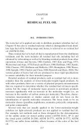
This is shown in Fig. <strong>22</strong>.2.<br />
The relationship between the vapor pressure and the temperature is established by the<br />
Antoine equation:<br />
A<br />
ln P �� �B (<strong>22</strong>.1)<br />
T<br />
The tangent to the saturation curve at the critical point is obtained by calculating the<br />
derivative of pressure with respect to temperature:<br />
By applying this expression to the critical point,<br />
dP P<br />
� A (<strong>22</strong>.2)<br />
2 dT T<br />
dPc PcA � � tg � (<strong>22</strong>.3)<br />
2 dT T<br />
c c<br />
This expression gives the slope of the line tangent to the saturation curve at the critical<br />
point. The equation of this straight line is:
Pc<br />
Pressure (atm)<br />
40<br />
P 273<br />
30<br />
20<br />
10<br />
1<br />
38,7<br />
vapor pressure curve<br />
R<br />
N<br />
M<br />
O S α<br />
20 40 60 80<br />
113<br />
89<br />
100 120 140<br />
<strong>MODELING</strong> <strong>AND</strong> UNDERST<strong>AND</strong>ING <strong>BLEVEs</strong> <strong>22</strong>.7<br />
Critical<br />
point<br />
Temperature (ºC) Tc<br />
FIGURE <strong>22</strong>.2 Saturation curve for butane and limiting conditions for BLEVE.<br />
tangent line to the critical point<br />
P � tg � � T � b (<strong>22</strong>.4)<br />
An example will show how this expression can be used. The value of the superheating<br />
limiting value will be calculated for butane. The equilibrium data corresponding to the critical<br />
point and to atmospheric pressure are:<br />
P � 38.7 atm T � 425.8 K<br />
c c<br />
P � 1 atm T � 272.5 K<br />
By introducing these data in the Antoine equation, the values of constants A and B for<br />
butane are found (the pressure expressed in atm and the temperature in K):<br />
A � 2769 B � 10.16<br />
The slope of the tangent to the saturation curve at the critical point is therefore:<br />
� �<br />
2769<br />
tg � � 38.7 � � 0.591<br />
2 425.8<br />
And the value of the ordinate at the origin, b, can be found by again introducing the<br />
values corresponding to the critical point, thus obtaining b ��213. In this way, the equation<br />
of the tangent line is obtained; its intersection with the horizontal line at P � 1 gives a
<strong>22</strong>.8 <strong>CHAPTER</strong> TWENTY-TWO<br />
temperature of 89�C (Fig. <strong>22</strong>.2). Therefore, for a vessel containing liquid butane, the minimum<br />
temperature required to reach (upon vessel failure) a superheating degree causing spontaneous<br />
nucleation (and therefore BLEVE) is 89�C; at this temperature, the spontaneous<br />
nucleation would occur at 1 atm.<br />
For the coordinate system used, with the origin at 0�C, the ordinate at the origin will be<br />
the pressure corresponding to 273 K,<br />
P173 � 0.591 � 273 � 213 ��52 atm<br />
Take for example a vessel containing butane at room temperature (20�C), in which liquid<br />
and vapor are at equilibrium at an absolute pressure of 2 atm (point M in Fig. <strong>22</strong>.2). If, due<br />
to the thermal radiation from a fire, the temperature increases to 70�C, the pressure inside<br />
the vessel will be 8 atm (point N). If, at these conditions, the vessel bursts (due to the failure<br />
of the material or an impact, for example), there will be an instantaneous depressurization<br />
from 8 atm to the atmospheric pressure. At the atmospheric pressure, the temperature of the<br />
liquid-vapor mixture will be �0.5�C (point O in Fig. <strong>22</strong>.2) and the depressurization process<br />
corresponds to the vertical line between N and O. As this line does not reach the tangent to<br />
the saturation curve at the critical point, the conventional theory states that there will be no<br />
BLEVE strictly speaking: although there will be a strong instantaneous vaporization and<br />
even an explosion, nucleation in all the liquid mass will not occur.<br />
Instead, if during the heating process the liquid temperature reaches, for example, 89�C<br />
(point R in Fig. <strong>22</strong>.2), during the depressurization the tangent line will be reached (point S<br />
in Fig. <strong>22</strong>.2). In this case the conditions required (superheating) by the aforementioned<br />
spontaneous homogeneous nucleation would exist and a BLEVE explosion would occur.<br />
However, this conventional theory, although accepted by many authors, fails to explain<br />
some of the <strong>BLEVEs</strong> that have occurred.<br />
In fact, the use of the tangent line to the saturation curve at the critical point as the<br />
limiting value for the occurrence of a BLEVE implies a margin of safety. The experimental<br />
data seem to indicate that the difference between the real superheating limit required to<br />
originate a BLEVE and the value thus obtained is in the range of 15 to 25�C (Table <strong>22</strong>.3).<br />
This is because when the substance is depressurized to reach the superheating limit line,<br />
there is also a slight decrease in its temperature. Thus, to reach the intersection point between<br />
the tangent at the critical point and the straight line at P � 1 atm (superheat temperature<br />
limit), it is necessary to start from a higher temperature. If, from this new temperature, a<br />
vertical line is drawn, a new limit temperature will be obtained for the line P � 1 atm.<br />
Connecting this new point to the critical point, a new superheating limit line will be obtained<br />
which is nearer to the real situation than the tangent line. The following expression has been<br />
suggested (Sigalés and Trujillo, 1990) for the calculation of this superheating limit:<br />
T � T � 0.8<strong>22</strong>06 T � 0.89485 T (<strong>22</strong>.5a)<br />
g s cr s<br />
where T g is the superheat temperature limit and T s is the saturation temperature corresponding<br />
to atmospheric pressure. For many organic and inorganic liquids the superheat temperature<br />
limit values are within 88 to 92% of the critical temperature. Reid (1976) used the equationof-state<br />
of Redlich-Kwong to obtain the following expression:<br />
T� � 0.895 � T (<strong>22</strong>.5b)<br />
g cr<br />
The difference between the temperatures calculated from these two expressions ranges<br />
from �1�C to�8�C for the substances included in the table (Armet, 1997).<br />
However, this is a theoretical treatment and some authors (e.g., Casal et al., 1999) doubt<br />
the applicability of these predictions to a real case. In the heating of a large vessel by a fire,<br />
there are probably some aspects that can make it difficult to predict the BLEVE occurrence.<br />
Amongst these we can cite the liquid temperature stratification, which can significantly affect<br />
the thermodynamic conditions inside the vessel. The content of a tank is not heated uniformly
TABLE <strong>22</strong>.3 Calculation of the Superheat Temperature Limit for Diverse Substances<br />
<strong>22</strong>.9<br />
Substance Formula T s,K T c,K P cr, atm ln P cr A B tg � b, atm T R,K T g,K ,K<br />
T� g<br />
Water<br />
Carbon dioxide<br />
Ammonia<br />
Phosgene<br />
Methane<br />
Ethane<br />
Ethylene<br />
Propane<br />
Propylene<br />
n-Butane<br />
n-Pentane<br />
n-Hexane<br />
n-Heptane<br />
n-Octane<br />
Ethyl eter<br />
Chlorine<br />
H 2O<br />
CO 2<br />
NH 3<br />
COCl 2<br />
CH 4<br />
C 2H 6<br />
C 2H 4<br />
C 3H 8<br />
C 3H 6<br />
C 4H 10<br />
C 5H 12<br />
C 6H 14<br />
C 7H 16<br />
C 8H 18<br />
(C 2H 5) 2O<br />
Cl 2<br />
373<br />
195<br />
240<br />
281<br />
111.5<br />
184.4<br />
169.1<br />
231.1<br />
<strong>22</strong>5<br />
272.5<br />
309.3<br />
342<br />
371.3<br />
398.8<br />
307.6<br />
238.4<br />
647<br />
304<br />
406<br />
455<br />
191<br />
305<br />
282.7<br />
369.8<br />
365.3<br />
425.8<br />
470.2<br />
507.8<br />
539.8<br />
569.2<br />
467<br />
419<br />
217.7<br />
73<br />
112.3<br />
56<br />
45.8<br />
48.8<br />
50.9<br />
43<br />
45<br />
38.7<br />
33<br />
29.5<br />
26.8<br />
24.7<br />
35.5<br />
93.5<br />
5.38312<br />
4.29046<br />
4.72117<br />
4.02535<br />
3.82428<br />
3.88773<br />
3.92986<br />
3.76120<br />
3.80666<br />
3.65584<br />
3.49651<br />
3.38439<br />
3.28840<br />
3.20680<br />
3.56953<br />
4.53796<br />
4741<br />
2333<br />
2771<br />
2958<br />
1024<br />
1812<br />
1654<br />
2317<br />
<strong>22</strong>30<br />
2767<br />
3160<br />
3545<br />
3911<br />
4272<br />
3217<br />
2510<br />
12.71<br />
11.96<br />
11.55<br />
10.53<br />
9.18<br />
9.83<br />
9.78<br />
10.03<br />
9.91<br />
10.15<br />
10.<strong>22</strong><br />
10.37<br />
10.53<br />
10.71<br />
10.46<br />
10.53<br />
2.4656<br />
1.8429<br />
1.8878<br />
0.8001<br />
1.2856<br />
0.9499<br />
1.0534<br />
0.7286<br />
0.7520<br />
0.5906<br />
0.4717<br />
0.4056<br />
0.3597<br />
0.3257<br />
0.5236<br />
1.3368 ;<br />
�1378<br />
�487<br />
�654<br />
�308<br />
�200<br />
�241<br />
�247<br />
�<strong>22</strong>6<br />
�230<br />
�213<br />
�189<br />
�176<br />
�167<br />
�161<br />
�209<br />
�467<br />
559<br />
265<br />
347<br />
386<br />
156<br />
255<br />
235<br />
312<br />
307<br />
362<br />
403<br />
436<br />
467<br />
497<br />
401<br />
350<br />
571<br />
270<br />
359<br />
404<br />
169<br />
270<br />
250<br />
328<br />
324<br />
379<br />
419<br />
453<br />
483<br />
510<br />
416<br />
370<br />
579<br />
272<br />
363<br />
407<br />
171<br />
273<br />
253<br />
331<br />
327<br />
381<br />
421<br />
454<br />
483<br />
509<br />
418<br />
375<br />
T� g<br />
� T g,K<br />
8<br />
2<br />
4<br />
3<br />
2<br />
3<br />
3<br />
3<br />
3<br />
2<br />
2<br />
1<br />
0<br />
�1<br />
2<br />
5
<strong>22</strong>.10 <strong>CHAPTER</strong> TWENTY-TWO<br />
during a fire. In diverse fire tests conducted on LPG tanks (Towsend et al., 1974; Appleyard,<br />
1980; Birk and Cunningham, 1996), the temperature of the liquid varies from the tank bottom<br />
(where the liquid is cooler) to the top (where the liquid is warmer) (Birk, 1995). This<br />
temperature stratification is due to buoyancy effects. Therefore, the temperature stratification<br />
plays an important role in case of an accident. This is a field in which there is still interesting<br />
research to be done.<br />
<strong>22</strong>.4 ESTIMATION OF BLEVE EFFECTS<br />
<strong>22</strong>.4.1 Thermal Radiation<br />
When a BLEVE explosion involves a flammable substance, it is usually followed by a fireball<br />
and intense thermal radiation will be released. The thermal energy is released in a short<br />
time, usually less than 40 seconds (although this time is a function of the mass in the tank).<br />
The phenomenon is characterized from the first moments by strong radiation; this eliminates<br />
the possibility of escaping for the persons nearby (who also will have suffered the effects<br />
of the blast).<br />
The parameters that must be evaluated for predicting the effects of a fireball are the<br />
diameter, duration, and thermal radiation at any given distance. In this section, a methodology<br />
is described to estimate these values.<br />
Diverse authors have proposed correlations for the prediction of the diameter and duration<br />
of a fireball originated by a given mass of fuel (CCPS, 1994). Most of them have the<br />
following general expression:<br />
b D � a � M (<strong>22</strong>.6)<br />
e t � c � M (<strong>22</strong>.7)<br />
where a, b, c, and e are empirical or semiempirical constants. A comparative study of 16 of<br />
these expressions has been made (Satyanarayana et al., 1991) (Table <strong>22</strong>.4).<br />
These authors compared the predictions from the diverse equations to real data from<br />
several explosions. The statistical analysis showed that the ‘‘best’’ correlation for the estimation<br />
of fireball diameter was the one proposed by Gayle (2), followed by those proposed<br />
by Marshall, Roberts, TNO, and High. Concerning the duration of the phenomenon, no<br />
comparison was possible, as there were no real data in the literature. Therefore, the expression<br />
proposed by Gayle could also be used. In another analysis carried out with 23 equations,<br />
Capdevila (1994) showed that the best ones were those proposed by Gayle (2), Marshall,<br />
Roberts, Moorhouse, TNO, High and Clay et al. Other authors (e.g., Lefin et al., 1993) found<br />
significant differences between the correlations published.<br />
Therefore, it is rather difficult to establish which is really the best equation. Actually, and<br />
according to the previously comparative analysis, the diameter and duration of a fireball can<br />
be predicted using the following correlations:<br />
0.325<br />
D � 6.14 � M (<strong>22</strong>.8)<br />
0.340<br />
t � 0.41 � M (<strong>22</strong>.9)<br />
where the units are m (D), kg (M), and s (t).<br />
It is worth noting, however, that there are very few experimental data available to back<br />
up this type of comparative analysis. Furthermore, these data—obtained from real accidents<br />
in the case of large fireballs—are not always accurate, as often the films are incomplete or
TABLE <strong>22</strong>.4 Equations for Estimating Fireball Diameter and Duration<br />
<strong>MODELING</strong> <strong>AND</strong> UNDERST<strong>AND</strong>ING <strong>BLEVEs</strong> <strong>22</strong>.11<br />
Author Reference a b c e<br />
Gayle (1) (Bagster and Pitblado, 1989) 3.68 0.326 0.245 0.356<br />
Gayle (2) (Bagster and Pitblado, 1989) 6.14 0.325 0.410 0.340<br />
Brasie (Bagster and Pitblado, 1989) 3.80 0.333 0.300 0.333<br />
Marshall (Bagster and Pitblado, 1989) 5.50 0.333 0.380 0.333<br />
Roberts (Lees, 1980) 5.80 0.333 0.450 0.333<br />
SRD a (Bagster and Pitblado, 1989) 6.00 0.333 0.005 — c<br />
Fay-Lewis (Fay and Lewis, 1977) 6.36 0.333 2.570 0.167<br />
Hardee (Bagster and Pitblado, 1989) 6.24 0.333 1.110 0.167<br />
Hasegawa (Bagster and Pitblado, 1989) 5.28 0.277 1.099 0.097<br />
Hasegawa-Sato (Hasegawa and Kato, 1978) 5.25 0.314 1.070 0.181<br />
Moorhouse (Bagster and Pitblado, 1989) 5.33 0.327 0.923 0.303<br />
TNO (Bagster and Pitblado, 1989) 6.48 0.325 0.852 0.260<br />
Maurer (Lihou and Maunde, 1982) 3.51 0.333 0.320 0.333<br />
High (Lihou and Maunde, 1982) 6.20 0.320 0.490 0.320<br />
HSCC b (Lihou and Maunde, 1982) 6.45 0.333 5.530 0.333<br />
API (Kayes, 1985) 5.33 0.327 1.089 0.327<br />
a Safety and Reliability Directorate.<br />
b Hot shell cold core model.<br />
c M is used as log10 M<br />
bad. The significant difficulty involved in experiments on a large scale complicates the study<br />
of fireball accidents that happen from time to time in the industry or in the transportation<br />
of certain materials.<br />
In fact, the lack of accuracy is not due only to the differences in the predictions from the<br />
diverse correlations. Another factor influencing it is the estimation of the fraction of the<br />
overall mass of fuel that really is involved in the fireball. As happens in many cases of risk<br />
analysis, the inaccuracy arises from the definition of the problem itself. It should be taken<br />
into account that some fuel has been leaving the vessel through the safety valves from the<br />
moment in which they opened; the amount released will depend on the time elapsed between<br />
this moment and that of the explosion. Furthermore, more fuel is entrained in the wake of<br />
the propelled fragments. The final result is that it is impossible to accurately establish the<br />
mass of fuel that will actually contribute to the fireball. This difficulty is found in the criteria<br />
recommended by different authors. Nazario (1988) suggests that the mass corresponding to<br />
the maximum capacity of the vessel should be used, and Pietersen and Cendejas (1985)<br />
recommend 90% of this value; other authors consider that only two-thirds or three-quarters<br />
of the initial fuel mass is finally involved in the fireball.<br />
However, in calculating the fireball’s diameter, most correlations include the mass of fuel<br />
affected by an exponent equal to one-third; this reduces considerably its influence on the<br />
value of D. This influence has been calculated (Calpe and Casal, 1989) for a maximum mass<br />
of 15,000 kg (Table <strong>22</strong>.5).<br />
Finally, the lack of accuracy is also due to the fire wake left by the fireball, which can<br />
reach a significant size; this modifies the flame surface and consequently the radiation that<br />
will reach a given point.<br />
In any case, the correlations mentioned in the previous paragraphs allow an approximate<br />
estimation of the size of the fireball. It should be taken into account, furthermore, that its<br />
size and position change continuously; therefore, the thermal radiation is not constant. The<br />
available films of BLEVE accidents show that the fireball grows quickly up to its maximum<br />
diameter, remaining at this diameter for a short time and then dissipating. Usually the cal-
<strong>22</strong>.12 <strong>CHAPTER</strong> TWENTY-TWO<br />
TABLE <strong>22</strong>.5 Influence of the Initial Mass<br />
of Fuel on the Fireball Diameter (values<br />
corresponding to a maximum mass of<br />
15,000 kg of LPG)<br />
% D, m<br />
100 140<br />
90 135<br />
75 127<br />
67 123<br />
culation of the radiation received by a given target is performed supposing that the fireball<br />
reaches its maximum size immediately after reaching a certain height.<br />
To estimate the radiation received by a surface located at a given distance, the solid body<br />
model can be applied:<br />
TABLE <strong>22</strong>.6 Predicting the Height (Top of the Flame) of the Fireball<br />
Accident Fuel Mass, kg<br />
h, m<br />
(observed)<br />
h, m<br />
(Eq. <strong>22</strong>.11)<br />
h, m<br />
(Eq. <strong>22</strong>.12)<br />
Crescent City a Propane 35,000 230 230 315<br />
Priolo Ethylene 80,000 <strong>22</strong>5 301 435<br />
Priolo Propylene 50,000 250 258 357<br />
a Lewis, 1991.<br />
I � � � F � E (<strong>22</strong>.10)<br />
p<br />
It is necessary, therefore, to know the value of the emissive power (E p), the view factor<br />
(F), the atmospheric transmissivity (�), and the distance between the flame and the target.<br />
To know this distance, it is necessary to estimate the height at which the fireball is located.<br />
In fact, this height is a function of the specific volume and the latent heat of vaporization<br />
of the fuel; therefore, strictly speaking, it varies with the substance. This is not usually taken<br />
into account. Diverse correlations have been proposed to estimate this height; one of the<br />
most simple ones is the following:<br />
H � 0.75 D (<strong>22</strong>.11)<br />
where H is the height at which the center of the fireball is located (in m) and D is its<br />
diameter, calculated with Eq. (<strong>22</strong>.8).<br />
Fay and Lewis (1977) proposed another correlation:<br />
1/3<br />
h � 12.7 V i<br />
(<strong>22</strong>.12)<br />
where h is the height of the top of the fireball (in m) and V i is the initial volume of vapor<br />
in the fireball (in m 3 ).<br />
Both expressions have been compared to the values corresponding to three real cases; the<br />
results can be seen in Table <strong>22</strong>.6 (the heights correspond to the top of the fireball; note that<br />
if Eq. (<strong>22</strong>.11) is used, (D/2) must be added to obtain the value of h).
<strong>MODELING</strong> <strong>AND</strong> UNDERST<strong>AND</strong>ING <strong>BLEVEs</strong> <strong>22</strong>.13<br />
The results from Eq. (<strong>22</strong>.11) are much closer to the observed values than those predicted<br />
by the other correlations; although only three cases imply a low statistical significance, this<br />
equation—which, furthermore, is the simplest one—can be recommended.<br />
Once more, we do not know for certain what fraction of the energy released is emitted<br />
as thermal radiation. In fact, this is the most important uncertainty in the calculation of the<br />
thermal radiation from a fireball. The following correlation has been proposed (Roberts,<br />
1982) to estimate this value:<br />
0.32<br />
� � 0.27 � P o (maximum value of � limited to 0.4) (<strong>22</strong>.13)<br />
where P o is the pressure (relative) in the vessel just before the explosion, in MPa. This<br />
expression was obtained from experimental data at laboratory scale, with amounts of fuel of<br />
a few kilograms; its validity at real scale has not been tested. The value of � ranges from<br />
0.13 to 0.35, according to diverse authors, and from 0.24 to 0.40 according to others. In any<br />
case, its maximum value is 0.4. From this radiation coefficient and the overall combustion<br />
energy, the energy radiated can be deduced. Then, the emissive power can be calculated<br />
from the following equation:<br />
� MHc p 2<br />
E � (<strong>22</strong>.14)<br />
� D t<br />
where H c is the combustion heat (kJ � kg �1 ) and t the time of duration of the fireball (s).<br />
Because the value of � can be inaccurate, another possibility is to use directly an arbitrary<br />
value of E p in the range of 200 to 350 kW � m �2 according to some authors (Bagster and<br />
Pitblado, 1989) and 200 kW � m �2 according to others (Pietersen and Cendejas, 1985).<br />
The maximum view factor is that corresponding to a sphere and a plane surface perpendicular<br />
to its radius. Due to the geometrical simplicity of this system, this factor can be<br />
calculated with a very simple equation:<br />
2 D<br />
F � (<strong>22</strong>.15)<br />
2 4r<br />
where r is the distance between the surface receiving the radiation and the center of the<br />
fireball [(R � x) in Fig. <strong>22</strong>.6]. For other positions of the surface of the target, the value of<br />
F must be corrected by using the angle formed by the surface and the surface perpendicular<br />
to the radius (see the example at the end of this section).<br />
Finally, the atmospheric transmissivity can be estimated from the following equation:<br />
<strong>22</strong>.4.2 Mechanical Energy Released in the Explosion<br />
�0.09<br />
� � 2.02 � (Pw � x) (<strong>22</strong>.16)<br />
When a vessel bursts in a BLEVE explosion, the mechanical energy contained inside is<br />
released (note that the units of pressure are energy per unit volume). The substance contained<br />
in the vessel instantaneously increases in volume due to the expansion of the vapor already<br />
existing in the vessel at the moment of the explosion and the superheated liquid, which<br />
undergoes a partial vaporization practically instantaneously (flash).<br />
The energy released in a BLEVE explosion is distributed among the following:<br />
• The energy of the pressure wave<br />
• The kinetic energy of the projectiles
<strong>22</strong>.14 <strong>CHAPTER</strong> TWENTY-TWO<br />
• The potential energy of the fragments (deformation plastic energy absorbed by the fragments)<br />
• The heating of the environment<br />
The relative distribution of the energy will change in relation to the particular conditions<br />
of the explosion. It is very difficult to establish accurately which amount of energy will<br />
contribute to the pressure wave (Capdevila, 1994). An important aspect is the type of failure<br />
(fragile or ductile). When the tank wall is heated and stressed, it may begin to thin due to<br />
plastic creep, and fissures may form. If this effect is very localized (for example, due to a<br />
jet fire) the fissure may stop growing as it enters thicker and stronger material (Birk, 1995).<br />
However, this fissure may result in sudden depressurization and a strong flashing effect in<br />
the liquid. As a result, pressure recovery can take place and this can restart the crack and<br />
finally lead to tank bursting and BLEVE.<br />
If the thermal effects are more widespread (as for example, in the case of a tank engulfed<br />
in a pool fire (Planas-Cuchi et al., 1996)), then the fissure may continue to grow and the<br />
tank may burst, resulting in a BLEVE. The propagation speed will depend on the mode of<br />
failure. If the wall thickness has decreased by plastic creep, the crack speed will be different<br />
than if the crack must propagate through thicker material by shear failure (Birk, 1995). There<br />
is an upper limit to the crack velocity, related to the material yield strength and density<br />
(Baum, 1982). The actual propagating velocity is usually less than the limiting velocity; it<br />
can reach velocities up to 200 m � s �1 .<br />
It has been suggested that in a fragile failure of a vessel, 80% of the energy released<br />
contributes to the creation of the pressure wave. In the case of a ductile breaking—in which<br />
large fragments of the vessel are propelled—the energy in the pressure wave is only 40%.<br />
In both cases, the rest of the energy becomes kinetic energy of the fragments, as the fourth<br />
contribution (heating of the environment) is negligible.<br />
In fact, most vessels or tanks are constructed with materials that are ductile at the operating<br />
conditions. A fragile failure is found only in very special conditions, when the stress<br />
reached by the material is much higher than its plastic limit. This only happens with tempered<br />
steel and glass. Therefore, BLEVE explosions usually consist of ductile breaking.<br />
Concerning the vapor initially in the vessel, the energy released in its expansion (from<br />
the breaking pressure in the vessel up to the atmospheric pressure) is:<br />
E � m(u � u ) (<strong>22</strong>.17)<br />
v 1 2<br />
where E v � the energy released in the expansion of the vapor (kJ)<br />
m � the mass of vapor already existing in the vessel at the moment of the failure<br />
(kg)<br />
u 1 � the internal energy of the vapor under the conditions at which the vessel bursts<br />
(kJ � kg �1 )<br />
u 2 � the internal energy of the vapor after the expansion up to atmospheric pressure<br />
(kJ � kg �1 ).<br />
Supposing that the expansion is isoentropic—due to the velocity at which it takes place—<br />
and that the vapor behaves as an ideal gas, this energy is (Prugh, 1991):<br />
� � � �<br />
(��1) / �<br />
P � V P 2<br />
a<br />
Ev � 10 � � 1 � (<strong>22</strong>.18)<br />
� � 1 � P �
<strong>22</strong>.4.3 Pressure Wave<br />
<strong>MODELING</strong> <strong>AND</strong> UNDERST<strong>AND</strong>ING <strong>BLEVEs</strong> <strong>22</strong>.15<br />
where P a is the atmospheric pressure (bar), V is the initial volume of vapor (m 3 ), � is the<br />
ratio of specific heats, and P is the pressure (bar) in the vessel just before the explosion.<br />
This energy can be expressed as TNT equivalent mass by using the adequate energy<br />
conversion factor (approximately 1,120 cal per gram of TNT),<br />
� � � �<br />
(��1) / �<br />
0.021 � P � V Pa � � 1 � P �<br />
W � � 1 � (<strong>22</strong>.19)<br />
TNT<br />
where W TNT is the equivalent mass of TNT (kg).<br />
Furthermore, if the vessel contained superheated liquid—as in the case of a BLEVE<br />
explosion—the released energy can be estimated approximately by using the same method.<br />
In this case, it must be taken into account that the mass of liquid will partly vaporize suddenly<br />
when reaching atmospheric pressure. The volume of this vapor at the pressure in the vessel<br />
just before the explosion must then be calculated; adding this fictitious volume to the real<br />
one, the equivalent mass of TNT will be:<br />
� � � �<br />
(��1) / �<br />
0.021 � P � V* Pa � � 1 � P �<br />
W � � 1 � (<strong>22</strong>.20)<br />
TNT<br />
where V* is the volume of vapor in the vessel plus the volume (at the pressure inside the<br />
vessel) of the vapor generated in the explosion, in m 3 :<br />
��<br />
�1 V* � V � V1 ƒ (<strong>22</strong>.21)<br />
�v V is the volume of vapor inside the vessel before the explosion, V 1 is the volume of liquid<br />
in the vessel before the explosion (m 3 ), and ƒ is the vaporization fraction (flash), i.e., the<br />
fraction of liquid which vaporizes in the depressurization; its value can be calculated with<br />
the following expression:<br />
0.38<br />
ƒ � 1 � exp (�2.63(C p/H v)(Tc � T b) � (1 � ((Tc � T o)/(Tc � T b))<br />
)) (<strong>22</strong>.<strong>22</strong>)<br />
where T c is the critical temperature of the substance (K), T b is the boiling temperature of<br />
the substance at atmospheric pressure (K), T o is the temperature of the substance in the<br />
moment of the explosion (K), and H v is the enthalpy of vaporization of the substance (kJ �<br />
kg �1 ).<br />
In fact, the blast contribution from the liquid will be affected by the lack of homogeneity<br />
in liquid temperature, decreasing as liquid temperature stratification increases (since liquid<br />
stratification reduces the average liquid temperature, the vaporization fraction will decrease).<br />
However, the actual knowledge of the liquid stratification phenomenon does not allow the<br />
suitable correction to be introduced into the blast calculation.<br />
The pressure wave generated by the explosion can be estimated from the equivalent TNT<br />
mass. This method implies a certain inaccuracy because in the BLEVE explosion of a vessel<br />
the energy is released at a lower velocity than in a TNT explosion and also because the<br />
volume of the vessel is much larger than that which would have the equivalent amount of a<br />
conventional explosive. Nevertheless, the method is simple and allows useful estimations.
<strong>22</strong>.16 <strong>CHAPTER</strong> TWENTY-TWO<br />
<strong>22</strong>.4.4 Missiles<br />
Due to the fact that the volume initially occupied by the energy released in the explosion<br />
is much larger than that which would occupy the equivalent mass of TNT, a correction must<br />
be made on the distance from the explosion center to the place in which the pressure wave<br />
must be estimated.<br />
This correction is carried out by using the scaled distance, d n, based on the similitude<br />
principle proposed by Hopkinson in 1915, according to which when two explosive charges<br />
of similar geometry and of the same explosive but different sizes, detonate in the same<br />
atmosphere, similar pressure waves are generated at the same scaled distance. This principle<br />
can also be applied to two different explosives, taking into account the fact that two types<br />
of explosion with the same overpressure give rise to the same effects. Because overpressure<br />
is a function of the distance and two different explosions do not cause the same overpressure<br />
at the same distance from the center of the explosion, the scaled distance is defined as that<br />
at which the overpressure has the same value for both explosions. The scaled distance is<br />
related to the real distance and to the equivalent TNT mass by the cubic root law,<br />
d<br />
dn � (<strong>22</strong>.23)<br />
1/3<br />
(� � W )<br />
where d n � the scaled distance (m � kg �1/3 )<br />
� � the fraction of the energy released converted in pressure wave<br />
d � the real distance (from the center of the explosion) at which the overpressure<br />
must be estimated (m).<br />
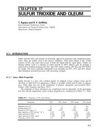
From the value of d n it is possible to estimate the overpressure by using a graph as shown<br />
in Fig. <strong>22</strong>.3.<br />
Because of their random behavior, projectiles from <strong>BLEVEs</strong> are one of the most difficult<br />
hazards to quantify (Birk, 1996). The fragments thrown by the explosion have a restricted<br />
and directional action, but with a larger radius of destructive effects than the pressure wave<br />
and the thermal effects of the fireball. These fragments can cause a domino effect if they<br />
destroy other tanks or equipment. The velocity required by a fragment to penetrate another<br />
similar tank ranges from 4 to 12 m � s �1 , and the maximum velocity that can be reached by<br />
the fragments in a BLEVE explosion—a function of the conditions at which the explosion<br />
occurs, the volume of vapor initially contained in the vessel, and the shape of the vessel—<br />
ranges from 150 to 200 m � s �1 .<br />
There are basically two kinds of projectiles from <strong>BLEVEs</strong>, as in the case of conventional<br />
explosions of containers:<br />
1. Primary projectiles, which are major pieces of the container<br />
2. Secondary projectiles, which are generated by the acceleration of nearby objects (pipes,<br />
bars, bricks, etc.)<br />
The number of primary projectiles (i.e., major pieces of the tank) will depend on the type<br />
of failure, the shape of the vessel, and the severity of the explosion. Typically, a BLEVE<br />
will involve a ductile failure; the cracks will propagate at lower velocity and without branching.<br />
The number of fragments will be less than if it were a fragile failure. The number of<br />
projectiles will be in the range of 2 to 15 (Baum, 1988, has reported that typically there will<br />
be less than five projectiles).<br />
In the case of cylindrical tanks, the initial crack usually follows an axial direction and<br />
then changes and follows a circumference (following, for example, a welding); thus, the<br />
vessel is usually broken into two pieces: the bottom of the tank and the rest of the vessel.<br />
TNT
Pressure wave (peak), bar<br />
6<br />
5<br />
4<br />
3<br />
2<br />
1<br />
0.8<br />
0.6<br />
0.5<br />
0.4<br />
0.3<br />
0.2<br />
0.1<br />
0.08<br />
0.06<br />
0.05<br />
0.04<br />
0.03<br />
0.02<br />
<strong>MODELING</strong> <strong>AND</strong> UNDERST<strong>AND</strong>ING <strong>BLEVEs</strong> <strong>22</strong>.17<br />
2 3 4 5 6 7 8 9 20 30 40 50 80<br />
Scaled distance, m·kg –1/3<br />
FIGURE <strong>22</strong>.3 Pressure wave as a function of the scaled distance. (Source: Van den Berg and<br />
Lannoy, 1993)<br />
The results of an analysis on 130 BLEVE cases, most of which occurred in cylindrical tanks,<br />
are shown in Table <strong>22</strong>.7.<br />
In cylindrical tanks there can also be three projectiles. If there are three fragments, there<br />
can be two types of failure. The vessel can be divided into two bottoms and the central body,<br />
or it can be first divided into two fragments, one bottom and the rest, and then this second<br />
fragment can be divided through the imaginary line that would separate the liquid and the<br />
vapor as shown in Fig. <strong>22</strong>.4. The bottom usually breaks by the welding; if there is no
<strong>22</strong>.18 <strong>CHAPTER</strong> TWENTY-TWO<br />
TABLE <strong>22</strong>.7 Number of Projectiles in BLEVE Accidents<br />
With projectiles Without projectiles<br />
Due to fire 89 24<br />
Without any fire 17 —<br />
Source: Holden and Reeves, 1985.<br />
welding, we can suppose that it will break at a distance from the end equal to 10% of the<br />
total length of the vessel.<br />
Concerning the direction, the projectiles will probably follow the direction of the cylinder<br />
axis. Data from 15 accidents (Holden and Reeves, 1985) provided the data in Table <strong>22</strong>.8,<br />
taking into account the 45� sectors at each side of the cylinder. Data obtained experimentally<br />
from 13 <strong>BLEVEs</strong> of 400-l vessels (Birk, 1996) gave somewhat different results; in some<br />
cases, this author observed that the tank remained flattened on the ground with both ends<br />
attached.<br />
The distance reached by projectiles from cylindrical tanks is usually greater than that<br />
reached by fragments from spherical vessels. The following expressions have been suggested<br />
(Baum, 1988; Birk, 1995) for the prediction of the range of cylindrical tank projectiles (tube<br />
fragments):<br />
3 0.33<br />
For tanks � 5 m in capacity: l � 90 � M (<strong>22</strong>.24a)<br />
3 0.1<br />
For tanks � 5 m in capacity: l � 465 � M (<strong>22</strong>.24b)<br />
where M is the mass of substance contained in the vessel (kg) and l is the range (m).<br />
The difference between the two expressions is due to the reduced relative effect of drag<br />
(ratio of drag force to tank weight) as tank size increases (when tank capacities exceed 5<br />
m 3 , the tank size is increased by increasing the tank length, not the tank diameter) (Birk,<br />
1995). These expressions were obtained assuming the tank is 80% full of liquid LPG at the<br />
time of failure, and for fragments launched at an optimum angle (45� to the horizontal).<br />
Because most fragments will not be launched at this angle, the real ranges will typically be<br />
less than those predicted by Eqs. (<strong>22</strong>.24a) and (<strong>22</strong>.24b).<br />
Recently, Baum (1999) has proposed the following expressions, which agreed very well<br />
with his experimental data, to estimate the upper bond of velocities for fragments from<br />
horizontal pressure vessels containing a high-temperature liquid:<br />
where<br />
0.375 1.25 � K<br />
End-cap missiles: U � 0.085 � a o<br />
(<strong>22</strong>.25)<br />
Psat ��<br />
I<br />
‘‘Rocket’’ missiles: U � (<strong>22</strong>.26)<br />
W<br />
P a<br />
P � � � R<br />
K � (<strong>22</strong>.27)<br />
2<br />
3<br />
o ƒ<br />
W � ao and I is the impulse (integrated pressure history of the closed end), which can be calculated<br />
as follows:
with<br />
FIGURE <strong>22</strong>.4 Common failure trends in cylindrical vessels.<br />
TABLE <strong>22</strong>.8 Probability of Projectile<br />
Launching in Cylindrical Vessels<br />
<strong>MODELING</strong> <strong>AND</strong> UNDERST<strong>AND</strong>ING <strong>BLEVEs</strong> <strong>22</strong>.19<br />
if P � P I � A � (P � t � P � (t � t ) � P � t ) (<strong>22</strong>.28)<br />
o sat o w sat o w sat e<br />
if P � P I � P � A � (t � t ) (<strong>22</strong>.29)<br />
o sat sat o e<br />
L<br />
t � (<strong>22</strong>.30)<br />
w<br />
a w<br />
� �<br />
Sector Probability<br />
1 0.62<br />
2 0.38<br />
1/2<br />
W<br />
to � (<strong>22</strong>.31)<br />
P � � � R<br />
sat<br />
L<br />
t � (<strong>22</strong>.32)<br />
e<br />
a m<br />
Some years ago it was considered that projectiles could reach 500 m as a maximum;<br />
however, in the accident in Mexico City, a projectile from a large cylindrical vessel traveled<br />
1,100 m and another one from a sphere went 600 m. The evacuation distance should therefore<br />
be 1,100 m for large cylindrical tanks.<br />
In the case of spherical vessels, it is much more difficult to predict the number of fragments.<br />
The analysis of a reduced number of cases (Pietersen and Cendejas, 1985) gave an<br />
average of eight fragments per accident. This author obtained the following correlation:<br />
N ��3.77 � 0.0096 V r<br />
(<strong>22</strong>.33)<br />
where N is the number of fragments and V r is the volume of the spherical vessel, ranging<br />
from 700 to 2,500 m 3 . However, taking into account the scattering of the data used by<br />
Pietersen, this correlation should not be considered very reliable.<br />
The direction followed by the projectiles from a spherical vessel is practically impossible<br />
to predict. The analysis of several cases shows that the distribution is not symmetrical; this<br />
must be attributed probably to the special position of the contact flame/vessel in each case,<br />
although other aspects (construction details, for example) can also have an influence.<br />
Finally, for projectile range, the analysis of 58 fragments from seven accidents has shown<br />
that 70% of the fragments reached distances less than 200 m. However, fragments from<br />
Source: Holden and Reeves, 1985.
<strong>22</strong>.20 <strong>CHAPTER</strong> TWENTY-TWO<br />
1<br />
45°<br />
2<br />
45°<br />
2<br />
FIGURE <strong>22</strong>.5 Distribution of projectiles from<br />
a cylindrical vessel.<br />
spherical vessels have reached 600 m (Mexico City) and even 700 m. The distance reached<br />
is usually smaller in the case of fragments from spherical vessels because they are less<br />
aerodynamical than those from cylindrical tanks. Different theoretical models have been<br />
suggested for the prediction of these maximum distances, but they are not very practical,<br />
since to apply them the mass and shape of the fragment should be known.<br />
<strong>22</strong>.5 PREVENTION MEASURES<br />
<strong>22</strong>.5.1 Sloping Ground<br />
<strong>22</strong>.5.2 Thermal Insulation<br />
In the case of an emergency that can lead to an accident of the BLEVE fireball type, it is<br />
very difficult to improvise adequate actions to control the situation. Any plan requiring the<br />
presence of people will be very dangerous because it is impossible to foresee when the<br />
explosion will occur. The actions should therefore be preventive and taken beforehand (Bestratén<br />
and Turmo, 1991b). The risk of a BLEVE can be reduced to tolerable levels if several<br />
of these measures can be taken at the same time. These are briefly discussed here.<br />
The installation must be designed in such a way that any leak of a liquid (for example,<br />
liquefied petroleum gas) could be immediately removed from the area in which there is the<br />
tank that must be protected. The ground should be smooth and with a slope of 2.5% (1.5%<br />
minimum); a draining system must lead to a trench or a tank far enough away to avoid<br />
contact between the flames and the tank. It must be taken into account that in case of wind,<br />
the flames can have an inclination of 45� as well as a significant drag and that they can<br />
reach approximately twice the diameter of the trench (Kletz, 1977).<br />
If the walls of the tank are blanketed with a fireproof material (with a low thermal conductivity),<br />
the heating of the vessel, and therefore its pressure increase, by an eventual fire is<br />
significantly delayed. Furthermore, in long emergencies, thermal insulation reduces the heat<br />
flow to the system and makes it possible for the safety valve to prevent the explosion<br />
(fireproofing relies significantly on the correct operation of the safety valve). It must be taken<br />
into account that these valves are not designed to solve these types of emergencies on their<br />
own, as their cross section should be excessive. Fireproofing ensures protection for a limited<br />
time (usually four to five hours). It is the most suitable device for road or railway tanks<br />
(Londiche and Guillemet, 1991).<br />
In any case, thermal insulation should be a complement, and other protective systems (for<br />
example, cooling of the vessel) should be installed. Another interesting point is that the<br />
structural elements (vessel legs) should also be insulated, to avoid the falling of the vessel<br />
1
<strong>MODELING</strong> <strong>AND</strong> UNDERST<strong>AND</strong>ING <strong>BLEVEs</strong> <strong>22</strong>.21<br />
under excessive heating (this is what happened with two of the spherical tanks in Mexico<br />
City; even after falling, however, surprisingly they did not explode). The thermal insulation<br />
should be installed in such a way that it could be effective in the event of a fire and also<br />
allow the tank surface and structural elements to be inspected periodically.<br />
<strong>22</strong>.5.3 Cooling with Water<br />
The usefulness of water sprinklers in protecting vessels exposed to the direct action of fire<br />
has been proven over many years. It is important to use the water from the first moments,<br />
with a layer of a certain thickness totally covering the wall to be cooled, especially those<br />
areas directly in contact with the flame. The required flowrate of water should be kept<br />
constant—in some cases, the action of firefighters and the consequent increase in water<br />
consumption have considerably decreased the pressure in the network and, thus, the water<br />
flowrate to the vessels—with a minimum value that will depend on the circumstances.<br />
To protect a fire-engulfed tank, the water flowrate will depend on the circumstances. If<br />
the safety valve is correctly designed and works normally, the water rate (Londiche and<br />
Guillemet, 1991) should not be less than 8 l � m �2 � min �1 ; however, diverse authors (Maddison,<br />
1989) consider that reducing the water flowrate below 10 l � m �2 � min �1 is dangerous<br />
if there is direct contact with the flame; a flowrate of 15 l � m �2 � min �1 has been recommended<br />
(Londiche and Guillemet, 1991; Nazario, 1988; Vílchez et al., 1993) as a general<br />
criterion. To have an efficient cooling effect, water should be applied before the temperature<br />
of the wall reaches 80�C. If there is no flame impingement, only thermal radiation, smaller<br />
flowrates can be used.<br />
If there is flame impingement on the wall, the thermal flux will depend on the type of<br />
flame (for a pool fire it can be approximately 100 kW � m �2 , while for a highly turbulent<br />
flame it can reach 350 kW � m �2 ). In this case, for the zone of the wall located above the<br />
liquid surface, flowrates even larger than 25 l � min �1 � m �2 may be required.<br />
Another aspect to be taken into account is that all safety elements—valves, pipes, etc.—<br />
should be designed to resist the action of fire and the high temperatures that will be reached<br />
during the emergency; otherwise, they will collapse in the first moments, especially if there<br />
is direct contact with the flames.<br />
<strong>22</strong>.5.4 Pressure Reduction<br />
If pressure is reduced, the walls of the vessel will be exposed to less force and the risk of<br />
explosion if the temperature increases will be lower. As a general criterion, API recommends<br />
the installation of devices able to reduce the pressure up to approximately 7 bar (relative)<br />
or up to half of the design pressure in 15 minutes. If the ground is sloped and the vessel is<br />
thermally insulated, this time can be longer. The depressurization can require a remote control<br />
valve besides the safety valve. The released material should be eliminated in safe conditions<br />
(Shebeko et al., 1996), e.g., with a torch. It should also be taken into account that<br />
in some cases a strong depressurization can cause extremely low temperatures, leading to<br />
fragile conditions in the steel.<br />
<strong>22</strong>.5.5 Mounding or Burying<br />
The possibility of either totally or partially burying the vessel has been suggested. This<br />
provides good protection against thermal radiation for a very long time period, as well as<br />
against missiles impacts. However, this measure has many disadvantages, primarily the eventual<br />
corrosion in the tank walls.
<strong>22</strong>.<strong>22</strong> <strong>CHAPTER</strong> TWENTY-TWO<br />
<strong>22</strong>.5.6 Water Barriers<br />
This is a relatively new system in which a set of sprayers generates curtains of fine water<br />
spray. The barriers retain the vapor released from the leak, thus reducing the possibility of<br />
ignition, and disperse them into the atmosphere.<br />
<strong>22</strong>.5.7 Protection from Mechanical Impacts<br />
<strong>22</strong>.5.8 Overflow<br />
Tanks containing materials stored at temperatures higher than their boiling temperatures at<br />
atmospheric pressure must be protected from impacts from cranes or other equipment or<br />
moving vehicles. A special case, not treated here, is the protection of tank cars.<br />
This is an incident that has caused a number of <strong>BLEVEs</strong>. Nowadays it is much less common,<br />
however, and adequate devices are installed to avoid it (level controls, safety valves).<br />
<strong>22</strong>.5.9 Minimum Separation Distances<br />
The minimum distances between vessels are usually established by regulations and will not<br />
be discussed here. They are important from the point of view of thermal radiation, and<br />
particularly to avoid direct contact between the flames from the fire in one piece of equipment<br />
and the wall of another vessel. They do not guarantee protection, however, in the case of an<br />
explosion (blast, projectiles).<br />
<strong>22</strong>.5.10 Actuation on the Initiating Mechanisms<br />
Diverse systems have been proposed to avoid homogeneous nucleation. These include installing<br />
aluminum mesh inside the tank and adding nuclei that initiate boiling. However,<br />
these systems are still being investigated, except for very specific applications.<br />
<strong>22</strong>.6 EXAMPLE CALCULATION OF BLEVE FIREBALL EFFECTS<br />
A tank with a volume of 250 m 3 , 80% filled with propane (stored as a pressurized liquid at<br />
room temperature), is heated by a fire up to 55�C (�19 bar) and bursts. The thermal radiation<br />
and the pressure wave must be estimated at a distance of 180 m.<br />
Data:<br />
Room temperature � 20�C; H R � 50% (partial pressure of water vapor, 1155 Pa); � �<br />
1.14; H v � 4.3 � 10 5 J � kg �1 ; H c � 46,000 kJ � kg �1 ; T cr � 369.8 K; T boil. atm. p. � 231.1 K;<br />
� liquid, 20�C � 500 kg � m �3 , � liquid, 55�C � 444 kg � m �3 ; � vapor, 55�C � 37 kg � m �3 ; Cp liquid �<br />
2,4 � 10 3 J � kg �1 � K �1 .<br />
Solution:<br />
First of all, the mass of propane involved is calculated:<br />
kg<br />
3<br />
M � Vl � �liq.,20�C � (0.8 � 250m)� 500 � 100,000 kg<br />
3 m
Schematic diagram:<br />
H<br />
R<br />
FIGURE <strong>22</strong>.6 Position of fireball and target.<br />
1. Estimation of thermal radiation<br />
By using Eq. (<strong>22</strong>.8), the fireball diameter is estimated:<br />
d<br />
x<br />
<strong>MODELING</strong> <strong>AND</strong> UNDERST<strong>AND</strong>ING <strong>BLEVEs</strong> <strong>22</strong>.23<br />
α<br />
0.325 0.325<br />
D � 6.14 � M � 6.14 � 100000 � 259 m<br />
Its duration is estimated with Eq. (<strong>22</strong>.9)<br />
0.340 0.340<br />
t � 0.41 � M � 0.41 � 100000 � 20.5 s<br />
And the height reached by the fireball is estimated by Eq. (<strong>22</strong>.11):<br />
H � 0.75 � D � 0.75 � 259 � 194 m<br />
The distance between the flame and the target, according to Fig. <strong>22</strong>.6, can be calculated<br />
as follows:<br />
2 2 2 2<br />
x � �H � d � R � �194 � 180 � 129.5 � 135 m<br />
The atmospheric transmissivity will be, according to Eq. (<strong>22</strong>.16):<br />
�0.09 �0.09<br />
� � 2.02 � (Pw � x�) � 2.02 � (1155 � 135) � 0.69<br />
The view factor is calculated with Eq. (<strong>22</strong>.15):<br />
2 2<br />
D 259<br />
F � � � 0.24<br />
2 2<br />
4 r 4 � 264.5<br />
Taking a value of � � 0, 25, the emissive power is [Eq. (<strong>22</strong>.14)]:<br />
� MH 0.25 � 100000 � 46000<br />
Ep � � � 266 kW � m<br />
2 2<br />
� Dt � � 259 � 20.5<br />
c �2<br />
The radiation intensity on a surface perpendicular to the radiation will be:<br />
α<br />
α<br />
α
<strong>22</strong>.24 <strong>CHAPTER</strong> TWENTY-TWO<br />
On a vertical surface,<br />
And on a horizontal surface,<br />
�2<br />
I � � � F � Ep � 0.69 � 0.24 � 266 � 44 kW � m<br />
�2<br />
Iv � I � cos � � 44 � 0.68 � 30 kW � m<br />
�2<br />
Ih � I � sin � � 44 � 0.73 � 32.3 kW � m .<br />
2. Estimation of pressure wave<br />
The overpressure is estimated from Eqs. (<strong>22</strong>.20), (<strong>22</strong>.21), and (<strong>22</strong>.<strong>22</strong>):<br />
ƒ � 1 � e<br />
<strong>22</strong>.7 NOMENCLATURE<br />
(�2.63�C /H �( T �T )�(1�(T �T / T �T ) 0.38<br />
p v c b c o c b ))<br />
(�2.63�(2.4�10 3/4.3�10 5)�(369.8�231.1)�(1�((369.8�328)/(369.8�231.1)) 0.38))<br />
� 1 � e � 0.525<br />
��<br />
� 444<br />
l 3<br />
V* � V � Vl � ƒ � � 50 � 200 � 0.525 � � 1310 m<br />
� 37<br />
v<br />
(��1)/�<br />
0.021 PV* Pa 0.021 � 19 � 1310<br />
� � � � � �<br />
� �<br />
(1.14�l)/1.14<br />
1 � � � �<br />
WTNT � � 1 � �<br />
� � 1 P 1.14 � 1<br />
� 1 � � 1133 kg<br />
19<br />
admitting that 40% of the released mechanical energy is transformed in pressure wave<br />
(ductile breaking of the vessel):<br />
d n is calculated with Eq. (<strong>22</strong>.23):<br />
(W ) � � � W � 0, 4 � 1133 � 453 kg<br />
TNT overpressure TNT<br />
d 180 �1/3<br />
dn � � � 23.4 m � kg<br />
1/3 1/3<br />
(� � W ) 453<br />
TNT<br />
With the TNT equivalence diagram (overpressure versus d n, Fig. <strong>22</strong>.3), an overpressure<br />
of 0.05 bar is found.<br />
A Constant in the Antoine equation (–); in Eqs. (<strong>22</strong>.28) and (<strong>22</strong>.29) bore cross-section<br />
area (m2 )<br />
a Constant (�)<br />
Sound velocity in the vapor (m � s�1 )<br />
Velocity of flow at exit plane (m � s�1 )<br />
ao am aw propagation velocity of the initial rarefaction wave (m � s �1 )<br />
B Constant in the Antoine equation (�)<br />
b Constant (�)<br />
c Constant (�)<br />
C p<br />
Specific heat at constant pressure (J � kg �1 � K �1 )<br />
D Diameter of fireball (m)<br />
d Distance from the center of the vessel to the point at which the overpressure must<br />
be calculated (m)
<strong>MODELING</strong> <strong>AND</strong> UNDERST<strong>AND</strong>ING <strong>BLEVEs</strong> <strong>22</strong>.25<br />
dn Normalized or scaled distance (m � kg�1/3 Ep )<br />
Emissive power (kW � m�2 Ev e<br />
)<br />
Energy released in the vapor expansion (kJ)<br />
Constant (�)<br />
F View factor (�)<br />
ƒ Vaporization factor (�)<br />
H Height at which the center of fireball is located (m)<br />
h Height at which the top of fireball is located (m)<br />
Hc Heat of combustion (kJ � kg�1 HR Hv )<br />
Relative humidity (%)<br />
Enthalpy of vaporization (kJ � kg�1 I<br />
)<br />
Radiation intensity (kW � m�2 ). In Eqs. (<strong>22</strong>.26), (<strong>22</strong>.28), and (<strong>22</strong>.29) impulse applied<br />
to closed end (bar � m2 � s)<br />
l range of cylindrical tank projectiles (m)<br />
L Length of ‘‘rocket’’ (m)<br />
M Mass of fuel (kg)<br />
m Mass of vapor existing initially (kg)<br />
N Number of fragments (�)<br />
P Vapor pressure (bar)<br />
Pa Pc Po Psat Pv R<br />
Atmospheric pressure (bar)<br />
Critical pressure (atm)<br />
Relative pressure (bar). In Eqs. (<strong>22</strong>.28) and (<strong>22</strong>.29) rupture pressure (bar)<br />
Liquid saturation pressure (bar)<br />
Partial pressure of water (Pa)<br />
Vessel bore radius (m)<br />
Rƒ r<br />
fragment radius (m)<br />
Distance from the center of fireball to the target (m)<br />
T Temperature (K)<br />
Tc Tb Tg T�g To TR Critical temperature (K)<br />
Boiling temperature (K)<br />
Superheat temperature limit at atmospheric pressure Eq. (<strong>22</strong>.5a) (K)<br />
Superheat temperature limit at atmospheric pressure Eq. (<strong>22</strong>.5b) (K)<br />
Temperature of the substance at the moment of the explosion (K)<br />
Superheat temperature limit according to the tangent line to the vapor pressuretemperature<br />
curve at the critical point (K)<br />
Ts t<br />
Saturation temperature corresponding to atmospheric pressure (K)<br />
Time (s)<br />
te to tw Time required to expel the vessel content from the open end of the ‘‘rocket’’ (s)<br />
Time required to achieve a fully open breach (s)<br />
Time taken for the rarefaction wave to propagate from the break to the closed end<br />
of the ‘‘rocket’’ (s)<br />
U Missile velocity (m � s�1 )<br />
u Internal energy of the vapor (kJ � kg�1 )<br />
V Volume of vapor in the vessel (m3 )<br />
Vi Initial volume of vapor in the fireball (m3 Vr )<br />
Volume of the spherical vessel (m3 Vl )<br />
Volume of liquid in the vessel just before the explosion (m3 x<br />
)<br />
Distance between the flame surface and the target (m)<br />
W missile mass (kg)<br />
WTNT �<br />
Equivalent mass of TNT (kg)<br />
Angle formed by the abscissa axis and the tangent to the saturation curve at the<br />
critical point (�); also, angle formed by the radius of the fireball and the horizontal<br />
(�)<br />
� Fraction of the energy released converted in pressure wave (�)<br />
� Ratio of specific heats (�)
<strong>22</strong>.26 <strong>CHAPTER</strong> TWENTY-TWO<br />
<strong>22</strong>.8 REFERENCES<br />
� Radiation coefficient (�)<br />
� Density (kg � m�3 )<br />
�l Liquid density (kg � m�3 )<br />
�v Vapor density (kg � m�3 )<br />
Appleyard, R. D. 1980. Testing and Evaluation of the Explosafe System as a Method of Controlling the<br />
BLEVE, Report TP2740, Transportation Development Centre, Montreal.<br />
Armet, L. 1997. Private communication.<br />
American Society of Testing and Materials (ASTM). 1983. ‘‘A Guide to the Safe Handling of Hazardous<br />
Materials Accidents,’’ ASTM STP 825, ASTM, Philadelphia.<br />
Bagster, D. F., and R. M. Pitblado. 1989. ‘‘Thermal Hazards in the Process Industry,’’ Chemical Engineering<br />
Progress, vol. 85, pp. 69–75.<br />
Baum, M. R. 1992. ‘‘Development of the Breach Generated by Axial Rupture of a Gas-Pressurized Steel<br />
Pipe,’’ Journal of Pressure Vessel Technology, Transactions of the ASME, vol. 104, pp. 253–261.<br />
Baum, M. R. 1988. ‘‘Disruptive Failure of Pressure Vessels: Preliminary Design Guidelines for Fragment<br />
Velocity and the Extent of the Hazard Zone,’’ Journal of Pressure Vessel Technology, Transactions of<br />
the ASME, vol. 110, pp. 168–176.<br />
Baum, M. R. 1999. ‘‘Failure of a Horizontal Pressure Vessel Containing a High Temperature Liquid: the<br />
Velocity of End-Cap and Rocket Missiles,’’ Journal of Loss Prevention in the Process Industries, vol.<br />
12, pp. 137–145.<br />
Bestratén, M., and E. Turmo. 1991a. ‘‘Explosiones BLEVE (I): Evaluación de la Radiaciñ Térmica,’’<br />
Notas técnica de prevención NTP-293, Inst. Nac. Seg. Hig. Trab., Barcelona.<br />
Bestratén, M., and E. Turmo. 1991b. ‘‘Explosiones BLEVE (II): Medidas Preventivas,’’ Notas técnica<br />
de prevención NTP-294, Inst. Nac. Seg. Hig. Trab., Barcelona.<br />
Birk, A. M. 1995. ‘‘Scale Effects with Fire Exposure of Pressure-Liquefied Gas Tanks,’’ Journal of Loss<br />
Prevention in the Process Industries, vol. 8, pp. 275–290.<br />
Birk, A. M. 1996. ‘‘Hazards from Propane <strong>BLEVEs</strong>: An Update and Proposal for Emergency Responders,’’<br />
Journal of Loss Prevention in the Process Industries, vol. 9, pp. 173–181.<br />
Birk, A. M., and M. H. Cunningham. 1996. ‘‘Liquid Temperature Stratification and Its Effects on BLE-<br />
VEs and their Hazards,’’ Journal of Hazardous Materials, vol. 48, pp. 219–237.<br />
Calpe, J., and J. Casal. 1989. ‘‘BLEVE-Bola de Foc. Estudi Comparatiu de Models de Predicció<br />
d’Efectes,’’ in Proc. Conferència sobre seguretat ambiental, Reus, Spain, pp. 389–404.<br />
Capdevila, J. 1994. Programa de càlcul per a l’estimació d’efectes i conseqüències de l’accident BLEVE/<br />
bola de foc, Internal Report, CERTEC, Barcelona.<br />
Casal, J., H. Montiel, E. Planas, and J. A. Vilchez. 1999. Análisis del Riesgo en Instalaciones Industriales,<br />
Edicions UPC, Barcelona.<br />
Center for Chemical Process Safety (CCPS). 1994. Guidelines for Evaluating the Characteristics of<br />
Vapor Cloud Explosions, Flash Fires and <strong>BLEVEs</strong>, AIChE, New York.<br />
Fay, J. A., and D. H. Lewis. 1977. ‘‘Unsteady Burning of Unconfined Fuel Vapor Clouds,’’ in 16th<br />
International Symposium on Combustion, pp. 1397–1405.<br />
Hasegawa, K., and K. Kato. 1978. ‘‘Study of the Fireball Following Steam Explosion of n-Pentane,’’ in<br />
2nd. International Symposium on Loss Prevention, Heidelberg, pp. 297–305.<br />
Holden, P. L., and A. B. Reeves. 1985. ‘‘Fragment Hazards from Failures of Pressurized Liquefied Gas<br />
Vessels,’’ Chemical Engineering Symposium Series, no. 93, pp. 205–217.<br />
Kayes, P. J., ed. 1985. Manual of Industrial Hazard Assessment Techniques, Office of Environmental<br />
and Scientific Affairs, World Bank, Washington, DC.<br />
Kletz, T. 1977. ‘‘Protect Pressure Vessels from Fire,’’ Hydrocarbon Processing, vol. 56, August, pp. 98–<br />
102.<br />
Lees, F. P. 1980. Loss Prevention in the Process Industries, vol. 1, Butterworth-Heinemann, London, pp.<br />
519–528.
<strong>MODELING</strong> <strong>AND</strong> UNDERST<strong>AND</strong>ING <strong>BLEVEs</strong> <strong>22</strong>.27<br />
Lefin, Y., G. Mavrothalassitis, and J. P. Pineau. 1993. ‘‘Knowledge Gained from Hazard Studies on<br />
Accident Investigations,’’ Chemical Industry and Environment, Girona, Spain, ed. J. Casal, vol. 1, pp.<br />
93–106.<br />
Lewis, D. 1991. ‘‘Crescent City, Illinois: 21 June 1970,’’ Loss Prevention Bulletin, vol. 101, pp. 23–32.<br />
Lihou, D. A., and J. K. Maunde. 1982. Institute of Chemical Engineering Symposium Series, no. 71, pp.<br />
191–<strong>22</strong>4.<br />
Londiche, H., and R. Guillemet. 1991. ‘‘Comparison of Three Protective Devices for BLEVE Prevention,’’<br />
Loss Prevention and Safety Promotion in the Process Industries, vol. 1, pp. 551–564.<br />
Maddison, T. E. 1989. ‘‘The Fire Protection of LPG Storage Vessels. The Design of Water Spray Systems,’’<br />
LPGITA Seminar, U.K. October.<br />
Mañas, J. L. 1984. ‘‘<strong>BLEVEs</strong>, Their Nature and Prevention,’’ Fire, June, pp. 27–39.<br />
Mcdevitt, C. A., C. K. Chan, F. R. Steward, and K. N. Tennankore. 1990. ‘‘Initiation Step of Boiling<br />
Liquid Expanding Vapor Explosions,’’ Journal of Hazardous Materials, vol. 25, pp. 169–180.<br />
Nazario, F. N. 1988. ‘‘Preventing or Surviving Explosions,’’ Chemical Engineering, August, pp. 102–<br />
109.<br />
Pietersen, C. M., and S. Cendejas. 1985. Analysis of the LPG Accident in San Juan Ixhuatepec, Mexico<br />
City, TNO, Report 85-0<strong>22</strong>2, The Hague.<br />
Planas-Cuchi, E., J. Casal, A. Lancia, and L. Bordignon. 1996. ‘‘Protection of Equipment Engulfed in<br />
a Pool Fire,’’ Journal of Loss Prevention in the Process Industries, vol. 9, pp. 231–240.<br />
Prugh, R. W. 1991. ‘‘Quantify BLEVE Hazards,’’ Chemical Engineering Progress, vol. 87, February, pp.<br />
66–72.<br />
Reid, R. C. 1976. ‘‘Superheated Liquids,’’ American Scientist, vol. 64, pp. 146–156.<br />
Reid, R. C. 1979. ‘‘Possible Mechanism for Pressurized-Liquid Tank Explosions or <strong>BLEVEs</strong>,’’ Science,<br />
vol. 203, pp. 1263–1265.<br />
Roberts, A. F. 1982. ‘‘Thermal Radiation Hazards from Releases of LPG from Pressurised Storage,’’<br />
Fire Safety Journal, vol. 4, pp. 197–212.<br />
Satyanarayana, K., M. Borah, and P. G. Rao. 1991. ‘‘Prediction of Thermal Hazards from Fireballs,’’<br />
Journal of Loss Prevention in the Process Industries, vol. 4, pp. 344–347.<br />
Shebeko, Y. N., A. P. Shevchuck, and I. M. Smolin. 1996. ‘‘BLEVE Prevention Using Vent Devices,’’<br />
Journal of Hazardous Materials, vol. 50, pp. <strong>22</strong>7–238.<br />
Sigalés, B., and A. Trujillo. 1990. ‘‘Modelado de Estallido de Recipientes,’’ Ingeniería Química, October,<br />
pp. 465–473.<br />
Towsend, W., C. Anderson, J. Zook, and G. Cowgill. 1974. Comparison of Thermally Coated and<br />
Uninsulated Rail Tank Cars Filled with LPG Subjected to a Fire Environment, U.S. Department of<br />
Transport, Report no. FRA-OR8D, 75-32, Washington, DC.<br />
Van den Berg, A. C., and A. Lannoy. 1993. ‘‘Methods for Vapor Cloud Explosion Blast Modelling,’’<br />
Journal of Hazardous Materials, vol. 34, pp. 151–171.<br />
Vílchez, J. A., E. Planas-Cuchi, and J. Casal. 1993. ‘‘Safety Measures in LPG Storage Design,’’ Proceedings<br />
of the 6th Mediterranean Congress on Chemical Engineering, Fira de Barcelona, vol. 1, pp.<br />
353–354.