CASE STUDY: 40 STORY BRBF BUILDING LOS ANGELES - PEER
CASE STUDY: 40 STORY BRBF BUILDING LOS ANGELES - PEER
CASE STUDY: 40 STORY BRBF BUILDING LOS ANGELES - PEER

Create successful ePaper yourself
Turn your PDF publications into a flip-book with our unique Google optimized e-Paper software.
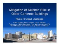
INVESTIGATEDESIGNREHABILITATE<strong>CASE</strong> <strong>STUDY</strong>:<strong>40</strong> <strong>STORY</strong> <strong>BRBF</strong> <strong>BUILDING</strong><strong>LOS</strong> <strong>ANGELES</strong>Anindya Dutta, Ph.D., S.E.Ronald O. Hamburger, S.E., SECBwww.sgh.com
Criteria• Three separate criteria:– CODE DESIGN– PERFORMANCE-BASED DESIGN• LATBC criteria– PERFORMANCE +• <strong>PEER</strong> TBI Guidelines2
Building Description• Approximate building floor plan– Tower: 170 ft X 107 ft– Podium• four levels of basement• plan dimensions of 227 ft X 220 ft3
Code Design• Building located in downtown Los Angeles with SDS =1.145 and SD1 = 0.52• Design follows all applicablebuilding code and standardprovisionsexcept4
Code Design – Contd.• Height limitation ignored5
Code Design• Gravity framing sized in RAM Structural System• Lateral Analysis and Design performed in ETABSusing 3D response spectrum analysis6
Gravity LoadingDescription/LocationSuperimposedDeadLive LoadRoof 28 psf 25 psf YesMechanical, Electrical at Roof Total of 100 kips - -Residential includingBalconies28 psf <strong>40</strong> psf YesCorridors, Lobbies and Stairs 28 psf 100 psf NoRetail 110 psf 100 psf NoParking Garage, Ramp 3 psf <strong>40</strong> psf 1 YesConstruction Loading 3 psf 30 psf NoCladding 15 psf - -Reducable<strong>PEER</strong> document showed 50 psf. SGH considered <strong>40</strong> psf in keeping with ASCE 7-057
Wind Design• ASCE 7-05 Method 2• Application ofhorizontal X and Ypressures in combinationwith torsion• Gust factor (G f ) computedusing 6.5.8.2 for dynamicallysensitive structures with 1%damping8
Wind DesignParameterBasic Wind Speed, 3 sec. gust (V)Basic Wind Speed, 3 sec gust (V), for serviceability winddemands based on a 10 year mean recurrence intervalValue85 mph67 mphExposureOccupancy CategoryImportance Factor (I w ) 1.0Topographic Factor (K zt ) 1.0Exposure Classification• Wind loads were statically applied in ETABS andbrace forces computedBIIEnclosedInternal Pressure Coefficient (GC pi ) ± 0.18Mean Roof Height (h) 544’-6”Wind Base Shear along Two Orthogonal Directions1436 kips and 2629 kips9
Seismic Design• Seismic analysis performed using the responsespectrum provided by <strong>PEER</strong>• Base Shear scaled to 85% of the staticlateral base shear obtained from equivalentstatic lateral force analysis• Base Shear is the story shear immediatelyabove podiumBasement walls and floormasses modeledRestraint provided only at wallbase10
Design Spectrum11
Seismic DesignParameterValueBuilding Latitude/LongitudeUndefinedOccupancy CategoryIIImportance Factor (I e ) 1.0Spectral Response Coefficients S DS = 1.145; S D1 = 0.52Seismic Design CategoryDLateral SystemBuckling restrained braced frames, nonmoment resisting beam column connectionsResponse Modification Factor (R) 7Deflection Amplification Factor (C d ) 5.5System Overstrength Factor (Ω 0 ) 2.0Building Period (T) using Cl. 12.8.2 3.16 sec 1Seismic Response Coefficient C s (Eq. 12.8-1) 0.051 W (Governed by C s-min from Eq. 12.8-5)Scaled Spectral Base Shear3504 kips (85% of Static Base Shear)Analysis Procedure1. Actual period from dynamic model: T Y = 5.05 sec; T X = 3.62 secModal Response Spectral Analysis12
Member Design• Member design performed using ANSI/AISC 341-05• Beams designed for unbalanced forcecorresponding to adjusted brace strengthβωRyPyscωRyPyscAssumed ω = 1.25, β = 1.1Ry =1.1 and Fy = 38 ksi13
Member Design• Columns designed for accumulated force (sum ofvertical components)corresponding to adjustedbrace strengths• Led to large compression and tension design forcesfor columns and foundations (Note: Attachment ofcolumns to foundations needs to be designed forsame forces used for column design)14
Member Design• Accommodation of the large forces required use ofsteel box sections filled with concrete• Upside: Using Chapter I of AISC 13 th Ed.a composite EIeff can be used.This contributed significantly to thelateral stiffness.• Braced frame beams were sized forhorizontal adjusted brace forces andunbalanced loading.15
Typical Member SizesTransverse Frame (Below 10 th Floor)Longitudinal Frame (Below 10 th Floor)16
LATBC-Performance Based Design• Wind and Gravity Design percode.• Seismic Design– Service level design• 2.5%-damped 25-year event• Essentially elastic behavior• Maximum drift of 0.005– MCE Verification• Nonlinear response history analysisused to verify adequacy for“collapse prevention” performance17
LATBC Design – Service Level• Used linear response spectrum analysis in ETABS.Max drift was 0.34%(
LATBC Design - Findings• Member sizes more economical.• Additional bays required in thetransverse direction below 10 thfloor eliminated.19
LATBC Design- MCE Analysis• Non linear response history analysis performedusing CSI Perform (Tx = 6.5s, Ty = 4.5s)• 7 ground motion pairs provided by <strong>PEER</strong>20
LATBC Design – MCE Acceptance Criterion• Acceptance based on mean demands from 7analyses– 3% maximum interstory drift– BRBs limited strain to 10 times yield (~0.013) based onobservance of data from a large number of tests.21
LATBC Design – MCE Story Drift22
<strong>PEER</strong> TBI- Performance “+”• Wind and Gravity Design followcode.• Seismic Design– Service level – 2.5% damped 43-yearspectrum• Essentially elastic performance• Drift limited to 0.005– MCE level• Max transient drift
<strong>PEER</strong> TBI Design• Started with LATBC design• Drift not satisfied above 30 th floor• Addition of outriggers at <strong>40</strong> th , 30 thand 20 th floors to control drift to
<strong>PEER</strong> TBI Design - MCE Story Drifts25
Summary & Conclusions• Three prototype designs developed– Code Design(without height limit)– LATBSDC-Performance Based Design– <strong>PEER</strong> TBI Performance Based Plus DesignBRB Capacity14<strong>40</strong>8kMCE Drift6534k5698k2.1%5060k1.7%CodeLATBPBD+CodeLATBPBD+1.2%0.9% 1.15%CodeLATBPBD+CodeLATB1.25%PBD+LongitudinalTransverseLongitudinalTransverse26
Summary & Conclusions• Performance-based Design resulted in moreeconomical member sizes and more practicalcolumn base connection• Building code for BRBs seems to be overlyconservative for high rise structures– Assumption that all braces yield simultaneously incorrect27