


Create successful ePaper yourself
Turn your PDF publications into a flip-book with our unique Google optimized e-Paper software.
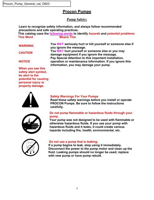
<strong>Procon</strong> <strong>Pumps</strong><br />
Pump Safety:<br />
Learn to recognize safety information, and always follow recommended<br />
precautions and safe operating practices.<br />
This catalog uses the following words to identify hazards and potential problems:<br />
This Word Means This<br />
WARNING<br />
CAUTION<br />
NOTICE<br />
When you see this<br />
safety alert symbol,<br />
be alert to the<br />
potential for causing<br />
personal injury or<br />
property damage.<br />
You MAY seriously hurt or kill yourself or someone else if<br />
you ignore the message.<br />
You MAY hurt yourself or someone else or you may<br />
damage equipment if you ignore the message.<br />
Pay Special Attention to this important installation,<br />
operation or maintenance information. If you ignore this<br />
information, you may damage your pump.<br />
Safety Warnings For Your <strong>Pumps</strong><br />
Read these safety warnings before you install or operate<br />
PROCON <strong>Pumps</strong>. Be sure to follow the instructions<br />
carefully.<br />
Do not pump flammable or hazardous fluids through your<br />
pump.<br />
Your pump was not designed to be used with flammable or<br />
otherwise hazardous fluids. If you use your pump with<br />
hazardous fluids and it leaks, it could create various<br />
hazards including fire, health, environmental, etc.<br />
Do not use a pump that is leaking.<br />
If a pump begins to leak, stop using it immediately.<br />
Disconnect the power to the pump motor and clean up the<br />
fluid. Leaking pumps should no longer be used; replace<br />
with new pump or have pump rebuilt.<br />
1
Keep your pump from leaking by following these three rules:<br />
1. Do not let the pump run dry.<br />
Do not let the pump run dry for more than 2 minutes. The self<br />
lubricating, internal parts protect the pump only against very brief dry<br />
runs.<br />
Running the pump dry may score or wear out the internal parts, causing<br />
performance loss. It may also damage the mechanical seal, causing the<br />
pump to leak fluid.<br />
2. Do not run the pump against a closed discharge.<br />
Running a pump against a closed or blocked discharge may cause<br />
pressure to build up to a dangerous level if there is no relief valve.<br />
Heat will build up in the pump and may cause the internal parts to wear<br />
out rapidly. It may also ruin the mechanical seal.<br />
PROCON's relief valves are designed to protect your pump against only<br />
short periods of over-pressure. PROCON's relief valves should not be<br />
used as flow control valves.<br />
3. Do not tamper with the setting of the relief valve.<br />
The relief valve is set at the factory to your specifications.<br />
Keep the floor around your pump dry. Make sure you keep the<br />
floor around your pump dry. If any liquid leaks onto the floor clean<br />
it up immediately.<br />
Do not touch the pump when there is liquid on the floor. Serious<br />
injuries can occur if you slip. Your pump operates with an electric<br />
motor. You can be electrocuted if you touch the pump when you<br />
are standing in liquid.<br />
You can increase your safety by using "ground fault interrupter<br />
(GFI)" type circuit breakers.<br />
Protect Children<br />
Keep children and other people who do not know how to<br />
operate the pump away from your pumps and the systems in<br />
which they are used. Children may not understand that<br />
equipment is sometimes dangerous to them and others.<br />
Never allow children to play with or operate your pumps.<br />
2
PROCON Vane <strong>Pumps</strong> are<br />
ideally suited for handling<br />
many clean fluids.<br />
PROCON Vane <strong>Pumps</strong> combine<br />
advantages that are not usually<br />
found in other pumps.<br />
Be prepared for emergencies.<br />
Be prepared for fires, injuries, or other emergencies.<br />
Keep a first aid kit and a fire extinguisher near the pumps<br />
and the systems in which they are used.<br />
Keep emergency numbers for doctors, ambulance<br />
services, hospital, and the fire department near your<br />
phone.<br />
A note to all employers<br />
Know your responsibilities as an employer.<br />
Make sure your employees know how to operate the pump<br />
safely.<br />
Make sure your employees are aware of the safety<br />
warnings in this catalog.<br />
Thoroughly train your employees about operating the<br />
pumps and other equipment safely.<br />
Keep the pumps in proper working condition. If you make<br />
unauthorized modifications to the pump, you may reduce<br />
the function and safety of the pump.<br />
Communicate all PROCON safety information to your<br />
customers.<br />
They have the unique ability to handle many<br />
liquids with low lubricating characteristics at<br />
relatively high pressures.<br />
Special Internal Materials and unique design<br />
eliminate metal-to-metal contact and make<br />
PROCON <strong>Pumps</strong> low in starting torque.<br />
Most PROCON <strong>Pumps</strong> are self-priming.<br />
PROCON Vane <strong>Pumps</strong> are quiet and have low<br />
vibration and pulsation characteristics.<br />
Flow remains constant over the entire pressure range.<br />
You can mount PROCON <strong>Pumps</strong> on NEMA 56C frame<br />
motors for a coupling drive or attach them to NEMA 48YZ<br />
motors with a V-band clamp.<br />
<strong>Procon</strong> Vane <strong>Pumps</strong> do not have to be lubricated and are<br />
virtually maintenance-free throughout their entire life except<br />
for cleaning the strainer.<br />
PROCON provides a quick and low cost factory rebuilding<br />
service.<br />
3
PROCON <strong>Pumps</strong> are available in a version, for use with potable water only, which<br />
is listed by NSF International. NSF develops standards and tests for the purpose<br />
of promoting public health. Because PROCON is concerned with public health,<br />
safety, and the environment, PROCON complies with these strict standards and<br />
maintains and NSF listing.<br />
PROCON is extremely proud that as of January 21, 1997, we received a Certificate<br />
of Registration of Quality System to I.S. EN ISO 9001:1994.<br />
Our Murfreesboro, Tennessee, and Mountmellick, Ireland operations are now ISO<br />
compliant.<br />
Model Number & Location<br />
Body<br />
Rotor<br />
Bearings<br />
Seals<br />
Strainer<br />
The Model Number identifies the pump and its<br />
configuration; it is stamped into the housing above the<br />
red name plate between the inlet and outlet ports. The<br />
date code is stamped into the housing to the left of the<br />
model number. It indicates the month and year that the<br />
pump was manufactured. In pumps manufactured after<br />
1990, the relief valve setting in PSI has been added to the<br />
model number suffix. If the pump has been rebuilt, an<br />
additional date code will be located on the shaft side of<br />
the housing at the discharge port.<br />
Components of the PROCON Pump<br />
Forged brass or cast stainless steel housings are rugged and long lasting.<br />
All pumps use stainless steel rotors.<br />
All PROCON vane pumps feature durable, dependable three-bearing<br />
construction to ensure top performance.<br />
An external ball bearing plus two internal carbon graphite bearings contribute to the over-all<br />
rugged construction.<br />
The external ball bearing is located outside the liquid chamber and is pre-lubricated and sealed<br />
for long, maintenance-free life.<br />
The rotor shaft is sealed by a mechanical seal.<br />
Standard pumps contain BUNA-N O-rings. The standard mechanical seal is<br />
BUNA-N with a carbon graphite seal face and a ceramic seat.<br />
Other elastomers, such as ETHYLENE PROPYLENE, NEOPRENE and<br />
FLUOROCARBON are available.<br />
The PROCON Series 1 vane pump is designed with an integral 100 mesh strainer.<br />
The strainer requires periodic maintenance. See Page 28 "inlet is clogged or<br />
restricted for instructions".<br />
4
Non-metal<br />
internal parts<br />
PROCON pumps are unique primarily because of the maintenance-free and selflubricating<br />
carbon graphite parts.<br />
PROCON pumps have special carbon graphite internal vanes, bearings, and<br />
liners. These allow low starting torque and no metal-to-metal contact.<br />
PROCON pumps have a long life and operate quietly because the carbon<br />
graphite is self-lubricating and heat resistant.<br />
Relief Valves Most PROCON pumps are available with or without a built-in relief valve.<br />
The relief valve temporarily protects against dangerous over-pressure.<br />
All relief valves are preset at the factory to your specifications (60 to 250 psi<br />
range available, 30 to 250 psi range also available on certain models, consult<br />
factory for details). At the specified relief valve setting, the flow will fully by-pass<br />
from the outlet to the inlet through the relief valve chamber. The specified relief<br />
valve setting is an average; individual pumps will vary both above and below the<br />
specified setting. The relief valve actually cracks and begins to by-pass flow at<br />
approximately 50 psi below the relief valve setting. Be advised that due to the<br />
design of the relief valve, the relief valve reacts to the difference in pressure<br />
between the inlet and the outlet. As a result, the highest pressure which the<br />
pump can develop at its discharge port is the inlet pressure plus the specified<br />
relief valve setting.<br />
If you need the full 250 psi discharge pressure rating of the pump, we<br />
recommend that you use an external relief valve supplied by others.<br />
The standard relief valve is made of a special high temperature plastic. Brass<br />
pumps with internal relief valves incorporate a stainless steel relief valve seat to<br />
prevent erosion.<br />
CAUTION: Do not tamper with the relief valve on your pump. If you think the relief<br />
valve needs to be reset, contact your PROCON factory representative.<br />
Options PROCON offers a wide range of options, so we can tailor-make a pump for most<br />
systems. Some of the options we offer include special seals, mounting flanges,<br />
rotations, and clearances.<br />
5
Series 1 Pump - Design Consistent Throughout All Series<br />
6
Series 1 With Integral Strainer<br />
Description, Standard Specifications, and Dimensions<br />
The clamp-in mounting style is shown in the<br />
photo; bolt on mounting is available.<br />
Standard Specifications<br />
Body Brass<br />
Capacity 15 –140 gph<br />
Nominal speed 1,725 rpm<br />
Max. Discharge pressure 250 psi<br />
Rotation Clockwise<br />
Dry Weight Approx. 2.75 lbs.<br />
Strainer area 3.25 sq in<br />
Self-priming (water) 6 ft. max. lift<br />
Dimensions of the Series 1 (Clamp-on mounting shown)<br />
7<br />
PROCON Series 1 pumps have the<br />
protection of an integral inlet strainer. The<br />
standard strainer in a 100 mesh wire<br />
screen. It traps particles that can cause<br />
serious damage to the pump.<br />
The strainer is equipped with a removable<br />
cap to allow periodic cleaning, every 4<br />
months under normal conditions. More<br />
frequently with hard or turbid water.
Series 2 Without Integral Strainer<br />
Series 2 Description, Standard Specifications, and Dimensions<br />
Standard Specifications<br />
Body Brass<br />
Capacity 15 –140 gph<br />
Nominal speed 1,725 rpm<br />
Max. Discharge pressure 250 psi<br />
Rotation Clockwise<br />
Dry Weight Approx. 2.5 lbs.<br />
Strainer area 3.25 sq in<br />
Self-priming (water) 6 ft. max. lift<br />
Dimensions of the Series 2 ( Clamp-on mounting shown)<br />
8<br />
PROCON's Series 2 <strong>Pumps</strong> have the<br />
same features as the Series 1 except<br />
they do not have the integral strainer.<br />
Series 1, 2, and 3 are available in 11<br />
flow rates: 15, 25, 35, 50, 60, 70, 80,<br />
100, 110, 125 and 140 gallons per hour<br />
at 250 psi.<br />
Clamp-on mounting style is shown in<br />
the photo; bolt-on mounting is also<br />
available
Clamp-on mounting style shown<br />
in photo; bolt-on mounting is also<br />
available.<br />
Series 3<br />
Description, Specifications, and Dimensions<br />
PROCON's Series 3 pumps boast all the<br />
unique features of other PROCON pumps.<br />
Because the pump body and all the metal<br />
parts are made from stainless steel, the<br />
Series 3 is well suited for pumping a<br />
variety of fluids not suitable with brass.<br />
Your PROCON factory representative can<br />
advise you on the correct pump for the<br />
fluids you intend to use.<br />
Standard Specifications<br />
Body stainless steal<br />
Capacity 15 –140 gph<br />
Nominal speed 1,725 rpm<br />
Max. Discharge pressure 250 psi<br />
Rotation Clockwise<br />
Dry Weight Approx. 2.75 lbs.<br />
Self-priming (water) 6 ft. max. lift<br />
Dimensions of the Series 3<br />
(clamp-on mounting with relief valve shown)<br />
9
Dimensions of the Series 1 (Clamp-on mounting shown)<br />
Dimensions of the Series 2 (Clamp-on mounting shown)<br />
Dimensions of the Series 3 (Clamp-on mounting with relief valve shown)<br />
Note: Specifications and dimensions are subject to change without notice.<br />
10
Series 4 and 5<br />
Description, Specifications, and Dimensions<br />
PROCON Series 4 & 5 are designed<br />
and built to meet your needs for flow<br />
rates ranging from 115 - 330 gallons<br />
per hour at 250 psi. These PROCON<br />
pumps Maintain all the quality<br />
features and construction of our<br />
Series 1, 2, & 3 pumps.<br />
Bolt-on mounting style shown (left)<br />
clamp-on style also available.<br />
Standard Specifications<br />
Body (series 4) brass<br />
Body (series 5) stainless steal<br />
Capacity 115 – 330 gph<br />
Nominal speed 1,725 rpm<br />
Max. Discharge pressure 250 psi<br />
Rotation clockwise<br />
Dry Weight Approx. 4.5 lbs.<br />
Self-priming (water) 6 ft. max. lift (330 gph model<br />
requires min 20 psi inlet<br />
pressure)<br />
Dimensions of the Series 4 & 5<br />
(bolt-on mounting shown)<br />
Note: Specifications and dimensions are subject to change without notice.<br />
11
Series 6<br />
Description, Specifications, and Dimensions<br />
Standard Specifications<br />
Body stainless steal<br />
Capacity 300 – 650 gph<br />
Nominal speed 1,725 rpm<br />
Max. Discharge pressure 250 psi<br />
Rotation clockwise<br />
Dry Weight Approx. 15 lbs.<br />
Minimum Inlet Pressure flooded (no inlet suction lift<br />
allowed)<br />
Dimensions of the Series 6 (bolt-on mounting only)<br />
Note: Specifications and dimensions are subject to change without notice.<br />
12<br />
PROCON's Series 6 is designed<br />
and built to meet your needs for<br />
higher flows. The flow rate capacity<br />
for this pump ranges from 300 to<br />
660 gallons per hour at 250 psi.<br />
This series pump is available only<br />
in bolt-on style.<br />
No integral relief valve is available.
Dimensions of the Series 4 and 5 (bolt-on mounting shown)<br />
Dimensions of the Series 6 (bolt-on mounting shown)<br />
13
Flow<br />
Rate<br />
(gph)<br />
Capacities and Horsepower Series 1, 2 &3<br />
Series 1, 2 & 3 Nominal Volume at 1725 RPM<br />
See note at bottom<br />
Gallons Per Hour<br />
Pressure (psi)<br />
14<br />
Brake Horsepower<br />
Pressure (psi)<br />
50 100 150 200 250 50 100 150 200 250<br />
140 143 141 139 137 135 0.17 0.28 0.40 0.52 0.63<br />
125 128 126 124 122 120 0.16 0.26 0.36 0.47 0.57<br />
110 111 109 107 105 103 0.15 0.25 0.34 0.44 0.54<br />
100 102 100 98 96 94 0.13 0.20 0.28 0.35 0.42<br />
80 82 80 78 76 74 0.12 0.18 0.25 0.32 0.39<br />
70 72 70 68 66 64 0.11 0.17 0.24 0.30 0.37<br />
60 62 60 58 56 54 0.10 0.16 0.23 0.29 0.35<br />
50 52 50 48 46 44 0.09 0.15 0.21 0.27 0.33<br />
35 37 35 33 31 29 0.08 0.14 0.19 0.24 0.29<br />
25 27 25 23 21 19 0.07 0.12 0.17 0.22 0.27<br />
15 17 15 13 11 --- 0.06 0.10 0.15 0.19 --
Capacities & Horsepower Graph<br />
Note: Nominal flow rating for each pump is based on operating the pump at a speed of<br />
1725 rpm, at a discharge pressure of 100 psi, with 70° F tap water as the fluid. The<br />
values are measured averages; individual pumps will deviate from these values.<br />
Because the pumps are positive displacement pumps, the discharge flow (in gallons per<br />
hour) is directly proportional to the speed at which the pump is being driven (800 rpm -<br />
minimum, 1725 rpm - maximum for series 6, 2300 rpm - maximum for Series 1, 2, 3, 4 &<br />
5). Use these charts to find your actual flow and minimum power requirements. For<br />
more information about how to determine model numbers, see Ordering PROCON<br />
<strong>Pumps</strong>, on Page 17.<br />
15
Flow<br />
Rate<br />
(gph)<br />
Series 4 & 5 Nominal Volume at 1725 RPM<br />
See note at bottom<br />
Gallons Per Hour<br />
Pressure (psi)<br />
16<br />
Brake Horsepower<br />
Pressure (psi)<br />
50 100 150 200 250 50 100 150 200 250<br />
330 331 330 328 327 326 0.33 0.55 0.78 1.00 1.22<br />
265 265 263 261 259 257 0.24 0.43 0.63 0.82 1.01<br />
240 243 240 236 232 228 0.21 0.37 0.54 0.70 0.86<br />
215 218 215 211 207 203 0.20 0.35 0.50 0.65 0.80<br />
190 193 190 186 182 178 0.18 0.33 0.47 0.61 0.75<br />
165 168 165 161 157 153 0.18 0.30 0.43 0.57 0.70<br />
140 143 140 136 132 128 0.16 0.28 0.40 0.52 0.64<br />
115 118 115 111 107 103 0.15 0.25 0.35 0.45 0.55<br />
Capacities & Horsepower Graph<br />
Note: Nominal flow rating for each pump is based on operating the pump at a speed of<br />
1725 rpm, at a discharge pressure of 100 psi, with 70° F tap water as the fluid. The<br />
values are measured averages; individual pumps will deviate from these values.<br />
Because the pumps are positive displacement pumps, the discharge flow (in gallons per<br />
hour) is directly proportional to the speed at which the pump is being driven (800 rpm -<br />
minimum, 1725 rpm - maximum for series 6, 2300 rpm - maximum for Series 1, 2, 3, 4<br />
& 5). Use these charts to find your actual flow and minimum power requirements. For<br />
more information about how to determine model numbers, see Ordering PROCON<br />
<strong>Pumps</strong>, on Page 17.
Flow<br />
Rate<br />
(gph)<br />
Series 6 Nominal Volume at 1725 RPM<br />
See note at bottom<br />
Gallons Per Hour<br />
Pressure (psi)<br />
17<br />
Brake Horsepower<br />
Pressure (psi)<br />
50 100 150 200 250 50 100 150 200 250<br />
660 663 660 657 654 651 0.50 0.95 1.40 1.85 2.35<br />
600 612 609 606 603 600 0.50 0.90 1.35 1.80 2.30<br />
540 552 549 546 543 540 0.50 0.85 1.30 1.70 2.00<br />
480 489 486 483 480 477 0.45 0.75 1.15 1.50 1.80<br />
420 435 432 429 426 423 0.45 0.70 1.00 1.35 1.75<br />
360 372 369 366 363 360 0.40 0.65 0.95 1.25 1.55<br />
300 303 300 297 294 291 0.35 0.55 0.85 1.15 1.45<br />
Capacities & Horsepower Graph<br />
Note: Nominal flow rating for each pump is based on operating the pump at a speed of<br />
1725 rpm, at a discharge pressure of 100 psi, with 70° F tap water as the fluid. The<br />
values are measured averages; individual pumps will deviate from these values.<br />
Because the pumps are positive displacement pumps, the discharge flow (in gallons per<br />
hour) is directly proportional to the speed at which the pump is being driven (800 rpm -<br />
minimum, 1725 rpm - maximum for series 6, 2300 rpm - maximum for Series 1, 2, 3, 4 &<br />
5). Use these charts to find your actual flow and minimum power requirements. For<br />
more information about how to determine model numbers, see Ordering PROCON<br />
<strong>Pumps</strong>, on Page 17.
Options For PROCON <strong>Pumps</strong><br />
Relief Valves: PROCON offers two types of relief valves which are preset at the factory<br />
according to your specifications.<br />
The solid relief valve protects against over-pressure and is made of a high temperature<br />
plastic. All brass pumps with a built-in relief valve are equipped with stainless steel relief<br />
valve seat. The addition of the stainless steel seat, begun in April 1997, will reduce<br />
erosion of the valve seat caused when the valve is unseated and flow is being<br />
recirculated.<br />
The by-pass valve also protects against over-pressure, but permits fluid flow from the<br />
inlet to the discharge of the pump when the pump is not operating. This valve features a<br />
spring-loaded by-pass valve inside the relief valve for use in certain beverage<br />
applications.<br />
The by-pass relief valve is available only on brass pumps - Series 1, 2 & 4.<br />
Series 6 pumps are not available with built-in relief valves.<br />
See Components Of The PROCON Pump for more information.<br />
CAUTION Internal PROCON relief valves are designed for protection<br />
against transient over pressure only. Do Not Use the internal relief valve<br />
as a flow or pressure control valve.<br />
Special Clearances: If you plan to pump fluids that are 150º F or higher ( 190º<br />
maximum), you will need special clearances and seals - Contact your PROCON factory<br />
representative for assistance.<br />
Special Seals: Standard mechanical face seals feature BUNA-N elastomers. For fluids<br />
that are not compatible with BUNA-N or are pumped at temperatures above 150º F,<br />
FLUOROCARBON, NEOPRENE, and ETHYLENE PROPYLENE are available. If you<br />
need these special seals, contact your PROCON factory representative for assistance.<br />
18
PROCON bolt-on style pump<br />
mounted to 56C-frame<br />
motor.<br />
Mounting Styles<br />
Mounting Styles for <strong>Procon</strong> <strong>Pumps</strong><br />
PROCON pumps can be mounted to two types of<br />
electric motors -- a carbonator style motor (NEMA<br />
48YZ frame) and a C-frame motor (NEMA 56C<br />
frame). Pump applications that require a motor of<br />
up to 0.75 horsepower, open drip proof<br />
construction and single phase power can be<br />
close-coupled to NEMA 48YZ frame, carbonator<br />
style motors.<br />
Use a V-band clamp to secure the mounting. You<br />
do not need to use any additional couplings or<br />
adapters. <strong>Pumps</strong> applications that require a motor<br />
greater than 0.75 horsepower, TEFC construction<br />
or 3 phase power can be mounted to NEMA 56C<br />
frame motors.<br />
You will need an aluminum "C-face" adapter and<br />
shaft coupling to mount your pump to a NEMA<br />
56C frame motor. The adapter and coupling are<br />
available from PROCON.<br />
For more information about how to mount pumps<br />
to these two types of motors, see Installing Your<br />
PROCON Pump.<br />
19
PROCON clamp-on style<br />
pump mounted to carbonator<br />
style motor.<br />
For more information about ordering motors, couplings,<br />
adapters, clamps and accessories, see Ordering<br />
PROCON <strong>Pumps</strong>.<br />
Besides PROCON, motors are available from your local<br />
electric motor distributor. NEMA 48YZ and NEMA 56C<br />
frame motors are available in 50 and 60 hertz as well as<br />
high and low voltage.<br />
NEMA 56C frames are available in single and threephase<br />
models as well as "open drip proof" (ODP),<br />
"totally enclosed fan cooled" (TEFC), and "explosionproof"<br />
versions from 0.25 to 3 horsepower.<br />
NEMA 48YZ frames are limited to single phase, open<br />
drip construction from 0.25 to 0.5 horsepower.<br />
20
Pre-Order Questionaire<br />
If you will furnish the following information, our sales engineers will be glad to<br />
recommend the model most suitable for your application.<br />
Application of Pump<br />
Fluid<br />
If other than clean tap water give the following information:<br />
Common Name<br />
Viscosity (SSU)<br />
pH<br />
Temperature: Normal °F Max °F Min °F<br />
Additives to fluid, if any<br />
Capacity<br />
Volume Required: GPH or GPM @ RPM<br />
Operating Pressure:<br />
Discharge Suction Lift of Head<br />
21
Options<br />
Mounting Style:<br />
Required Elastomer:<br />
Housing Material: Brass<br />
Clamp-on style 48YZ frame<br />
Buna-N<br />
Built-in Relief Valve (NOT AVAILABLE IN SERIES 6) Yes No<br />
Built-in Strainer (SERIES 1 ONLY) Yes No<br />
Name Title<br />
Company<br />
Address<br />
City State Zip<br />
Country<br />
Phone Fax E-Mail<br />
Please Quote On Units<br />
*** IMPORTANT ***<br />
Please E-Mail a scanned schematic of system the pump is to be used with.<br />
Indicate size of the smallest orifice in system (usually found in solenoid valve).<br />
"QUALITY PRODUCTS - DELIVERED ON TIME"<br />
22
Ordering PROCON <strong>Pumps</strong><br />
When you order a pump, you must include the following elements in your order<br />
number:<br />
1. Product Classification 7. Rotation / Slinger<br />
2. Food Grade Classification 8. Clearances<br />
3. Series 9. Valve Type and Configuration<br />
4. Mounting and Drive Classification 10. Pressure Range<br />
5. Flow Rate (Relief Valve Spring) Configuration<br />
6. Elastomer / Seal Configuration<br />
Select the appropriate Product and Food Grade Classification<br />
111A100F11AA The first character position specifies the Product Category. All<br />
PROCON Rotary Vane model numbers will begin with the digit "1".<br />
The second character position specifies if the pump is NSF Listed<br />
for use with potable water. The example model number shown on<br />
the left is an NSF Listed product. If it were not, the second digit<br />
would be a "0" rather than a "1 ". For more details regarding NSF<br />
Listed pumps, please contact the factory.<br />
Select the appropriate Series number<br />
111A100F11AA The third character position specifies the Series Number. There<br />
are six series offered within our Rotary Vane Product Line. They<br />
are discussed in detail on Pages 8, 9, 10 & 11. The example<br />
model number shown on the left is our Series 1 pump (brass<br />
housing; 3/8" NPT ports, with an integral strainer).<br />
Select the appropriate Mounting & Drive Configuration<br />
111A100F11AA The fourth character position specifies the Mounting and Drive<br />
Configuration. The three most common mounting styles are "A",<br />
"B" and "C". These and other styles are referenced in detail on<br />
Page 19.<br />
Select the desired Flow Rate<br />
111A100F11AA The fifth through the seventh character positions represent the<br />
Flow Rate of the pump. The example model number shown on the<br />
left is a 100 GPH pump. The flow rates available range from 15 to<br />
660 gallons per hour.<br />
23
Select the appropriate Elastomer/Seal Configuration<br />
111A100F11AA The eighth character position specifies the type of Elastomer used<br />
in the construction of the mechanical shaft seal assembly and orings.<br />
For most applications Nitrile is appropriate. This seal is<br />
appropriate for clean tap water at moderate temperatures. Other<br />
options available are Fluorocarbon, Ethylene Propylene and<br />
Neoprene<br />
Applications which involve a fluid other than clean tap water<br />
at moderate temperatures should be discussed with a<br />
PROCON Sales Engineer.<br />
Select the appropriate Rotation and Slinger Configuration<br />
111A100F11AA The ninth character position specifies the Rotation and Slinger<br />
Configuration. The majority of pumps manufactured by PROCON<br />
operate in a clockwise manner when viewed from the nameplate.<br />
<strong>Pumps</strong> which are designed to operate in a counter clockwise<br />
manner are also available.<br />
The slinger is standard in our Series 3 and Series 5 pumps, and is<br />
also available as an option in our Series 1, 2 and Series 4 pumps.<br />
The example model number shown on the left is a clockwise pump<br />
without a slinger. As a general rule slingers are not necessary. If<br />
you desire a brass pump with a slinger, please discuss your<br />
requirements with a PROCON Sales Engineer.<br />
Select the appropriate Clearances<br />
111A100F11AA The tenth character position specifies the internal Clearances. For<br />
pumps operating with fluid temperatures less than 150°F, standard<br />
clearances are appropriate so a "1" would be used in this position.<br />
Applications which require pumping a fluid between 150°F and<br />
190°F require special clearances (and special seals) so a "2"<br />
would be used in this position. Applications requiring elevated<br />
temperature capabilities should be discussed with a PROCON<br />
Sales Engineer.<br />
24
Select the appropriate Valve Type & Configuration:<br />
111A100F11AA The eleventh character position specifies the Valve Type &<br />
Configuration. The operation of the relief valve is discussed in<br />
detail on Page 7 and the different valve types are referenced on<br />
page 19. The example model number shown on the left has the<br />
"A" valve type, which is a by-pass style plastic relief valve. This<br />
configuration is commonly used in the beverage industry. The "B"<br />
valve type, which is a solid plastic relief valve is appropriate for<br />
use in most non-beverage applications.<br />
Select the appropriate Pressure Range and Pressure Setting:<br />
111A100F11AA250 The twelfth and final character position specifies the Pressure<br />
Range. In the example, the spring selected has a possible setting<br />
range of 150 to 250 PSI.<br />
Although not officially part of the model number, the three italicized<br />
digits following the model number specify the desired relief valve<br />
setting. This number will be stamped into the housing for<br />
identification purposes. A pump with no relief valve is designated<br />
by an "X" in the eleventh and twelfth character positions. (In this<br />
instance no setting would be referenced.)<br />
25
PROCON Model Number Matrix<br />
1 1 1 A 1 0 0 F 1 1 A A 2 5 0<br />
111A100F11AA250 Product Classification:<br />
1 - Rotary Vane Pump<br />
111A100F11AA250 Food Grade Classification:<br />
1 - NSF Listed<br />
0 - Non Food Grade<br />
111A100F11AA250 Series:<br />
Note: Brass <strong>Pumps</strong> are NSF listed for potable water only. Stainless steel<br />
pumps are NSF listed for potable water and carbonated water.<br />
1 - Brass, 3/8" NPT Ports w/Strainer<br />
(Formerly 1300 Series)<br />
2 - Brass, 3/8" NPT Ports (Formerly 1500 Series)<br />
3 - ST STL, 3/8" NPT Ports (Formerly 1600 Series)<br />
4 - Brass, 1/2" NPT Ports (Formerly 2500 Series)<br />
5 - ST STL, 1/2" NPT Ports (Formerly 2600 Series)<br />
6 - ST STL, 1" NPT Ports (Formerly 3600 Series)<br />
111A100F11AA250 Mounting & Drive Configuration:<br />
A - Clamp-on with .188" Double Flat Drive<br />
(Formerly "CO" prefix)<br />
B - Clamp-on with 1143 Bronze Coupling<br />
(Formerly "CB" prefix)<br />
C - Clamp-on with 1143-2 Plastic Coupling<br />
(formerly "CN" prefix)<br />
E - Bolt-on with single flat drive<br />
(Formerly no prefix all series except 3600)<br />
N - Bolt-on with key slot drive<br />
(Formerly no prefix for 3600 series)<br />
26
111A100F11AA250 Flow Rate:<br />
Series 1, 2, & 3 Series 4 & 5 Series 6<br />
015 – 15 gph 115 – 115 gph 300 – 300 gph<br />
(Formerly “21”) (Formerly “02”) (Formerly “05”)<br />
025 – 25 gph 140 – 140 gph 360 – 360 gph<br />
(Formerly “22”) (Formerly “03”) (Formerly “06”)<br />
035 – 15 gph 165 – 165 gph 420 – 420 gph<br />
(Formerly “05”) (Formerly “04”) (Formerly “07”)<br />
050 – 50 gph 190 – 190 gph 420 – 480 gph<br />
(Formerly “10”) (Formerly “05”) (Formerly “08”)<br />
060 – 60 gph 215 – 215 gph 540 – 540 gph<br />
(Formerly “09”) (Formerly “06”) (Formerly “09”)<br />
070 – 70 gph 240 – 240 gph 600 – 600 gph<br />
(Formerly “08”) (Formerly “07”) (Formerly “10”)<br />
080 – 80 gph 265 – 265 gph 660 – 660 gph<br />
(Formerly “07”) (Formerly “08”) (Formerly “11”)<br />
100 – 100 gph 330 – 330 gph<br />
(Formerly “04”) (Formerly “39”)<br />
110 – 110 gph<br />
(Formerly “32”)<br />
125– 125 gph<br />
(Formerly “33”)<br />
140 – 140 gph<br />
(Formerly “34”)<br />
111A100F11AA250 Elastomer / Seal Configuration:<br />
F NITRILE / TYPE 21 SEAL<br />
(Formerly No Suffix)<br />
G ETHYLENE PROPYLENE / TYPE 21 SEAL<br />
(Formerly "E" Suffix)<br />
R FLUOROCARBON / TYPE 21 SEAL<br />
(Formerly "V" Suffix)<br />
S NEOPRENE / TYPE 21 SEAL<br />
(Formerly "Z" Suffix)<br />
27
111A100F11AA250 Rotation / Slinger:<br />
Counterclockwise rotation cannot be obtained in Series 1<br />
<strong>Pumps</strong> (Integral Strainer)<br />
1 – Clockwise<br />
(Formerly No Suffix for 1300, 1500, 2500, & 3600 Series)<br />
2 - Counterclockwise<br />
(Formerly "R" Suffix for 1500 & 2500 Series)<br />
3 - Clockwise / Slinger<br />
(Formerly No Suffix for 1600 & 2600 or "K" Suffix)<br />
4 - Counterclockwise / Slinger<br />
(Formerly "R" Suffix for 1600 & 2600 Series<br />
or "KR" Suffix)<br />
111A100F11AA250 Clearances:<br />
1 - Standard Clearance<br />
2 - Special Clearance (Formerly "F" Suffix)<br />
111A100F11AA250 Valve Type & Configuration:<br />
A Plastic, bypass (SS HSG Seat)<br />
(Formerly No Suffix or "M" Suffix)<br />
B Plastic, Solid (SS HSG Seat)<br />
(Formerly "X" or "XM" Suffix)<br />
C Plastic, Balanced Bypass (SS HSG Seat)<br />
(Formerly "B" Suffix)<br />
D Plastic, Balanced Solid (SS HSG Seat)<br />
(Formerly "BX" Suffix)<br />
F Plastic, EXT ADJ Bypass (SS HSG Seat)<br />
(Formerly "P" or "PM" Suffix)<br />
G Plastic, EXT ADJ Solid (SS HSG Seat)<br />
(Formerly "PX" or "PXM" Suffix)<br />
X No Relief Valve<br />
(Formerly "A" Suffix)<br />
111A100F11AA250 Pressure Range (Relief Valve Spring):<br />
For the beverage industry, the default relief valve pressure<br />
setting is 250 psi.<br />
A 151 - 250 psi, Default Setting 170 psi<br />
(Formerly no Suffix)<br />
B 100 - 150 psi, Default Setting 130 psi<br />
(Formerly "L" Suffix)<br />
C 60 - 99 psi, Default Setting 99 psi<br />
(Formerly "H" Suffix)<br />
D 30 - 59 psi, Default Setting 50 psi<br />
(Formerly "D" Suffix )<br />
X No Setting<br />
111A100F11AA250 Pressure Setting (Relief Valve):<br />
Setting For Relief Valve Pressure in PSI (Pounds Per Square<br />
Inch).<br />
Note: The Relief Valve Pressure Setting is not part of the Model<br />
Number. This number is for customer reference.<br />
28
Mounting Accessories Series 1, 2, 3, 4 & 5<br />
Mounting Accessories – Series 1, 2, 3, 4 & 5 <strong>Pumps</strong><br />
If you are using a NEMA 48YZ motor, you should order clamp-on pumps. Order these<br />
parts to mount your pump to the motor. The parts that are indicated as "service parts"<br />
come standard with new pumps and are also available as replacement parts.<br />
To Order This Part Use This Number<br />
PROCON 100 mesh strainer (service part, Series 1) 1138<br />
PROCON metal coupling (service part for "B" Mounting Config.) 1143<br />
PROCON plastic coupling (service part "C" mounting Config.) 1143-2<br />
PROCON V-band clamp 1113<br />
If you are using a NEMA 56C frame motor, you should order bolt-on pumps. Order<br />
these parts to mount your NEMA 56C motor. PROCON does not supply fasteners for<br />
Series 1, 2, 3, 4, & 5.<br />
To Order This Part Use This Number<br />
PROCON three piece drive shaft coupling 3045<br />
PROCON pump / motor adapter 1048-1C<br />
Mounting Accessories - Series 6 <strong>Pumps</strong><br />
Series 6 pumps work only with a NEMA 56C frame motor.<br />
To Order This Part Use This Number<br />
PROCON three piece drive shaft coupling 3206-1<br />
PROCON pump/motor adapter 3207<br />
PROCON shaft key 3208<br />
fasteners for adapter and pump 3216<br />
29
Motor Applications<br />
NEMA 48YZ FRAME<br />
clamp-on carbonator motor, single phase, open drip proof<br />
To Order This Part Use This Number<br />
1/4 hp, 60/50 hertz, 220-240 volts 859<br />
1/4 hp, 60/50 hertz, 115 volts 803<br />
1/3 hp, 60/50 hertz, 100-120/200-240 volts 828<br />
1/3 hp, 60 hertz, 115 volts 806<br />
1/2 hp, 60/50 hertz, 100-120/200-240 volts 871<br />
3/4 hp, 60/50 hertz, 115/230 volts 872<br />
NEMA 56C FRAME<br />
frame bolt-on motor, 60/50 hertz, TEFC<br />
To Order This Part Use This Number<br />
1 hp, single phase, 115/208-230 volts 849<br />
1.5 hp, single phase, 115/208-230 volts 850<br />
2 hp, single phase 115/208-230 volts 851<br />
1 hp, three phase, 208-230/460 volts 844<br />
1.5 hp, three phase, 208-230/460 volts 845<br />
2 hp, three phase, 208-230/460 volts 846<br />
30
Notice<br />
Your pump can be ruined or its<br />
service life shortened if it does<br />
not meet these operating<br />
conditions at all times.<br />
See Intake (A)<br />
<strong>Pumps</strong> must have a fluid supply<br />
to the pump inlet greater than<br />
the pump's flow rating.<br />
Fluid must be compatible with<br />
the pump materials.<br />
Fluid must not contain any<br />
particles.<br />
Pump must not operate above<br />
its rated discharge pressure.<br />
Fluid flow should not stop<br />
suddenly while the pump is<br />
running.<br />
Operating pressure should be<br />
50 psi below PROCON's relief<br />
valve setting.<br />
Applications with operating<br />
temperatures above 150° F<br />
require oversized inlet piping.<br />
If using compressed air to purge<br />
the pump of fluid, install a<br />
coalescing filter in the air<br />
system to prevent contaminated<br />
air from entering the pump.<br />
We suggest that you use the<br />
precautionary measures and<br />
piping layout that follow. This<br />
layout promotes a long, troublefree<br />
life for your pumps.<br />
Piping Layout<br />
Suggested Piping Layout For PROCON <strong>Pumps</strong><br />
31<br />
Filters<br />
If particles may contaminate<br />
the fluid, use a particle filter (B)<br />
that is capable of filtering<br />
particles larger than 125<br />
microns. If the particles are<br />
abrasive, use a filter that is<br />
capable of removing virtually all<br />
of the particles.<br />
(See: Low Pressure Switch (C)<br />
If the pump may possibly<br />
experience insufficient fluid<br />
supply (low flow rate), install a<br />
pressure suction switch to<br />
prevent cavitation. This switch<br />
should be mounted or ported<br />
close to the pump inlet. Series<br />
1, 2, 3, 4 & 5 pumps may<br />
operate with as much as 6 feet<br />
of suction lift, with the<br />
exception of the 330 GPH<br />
models, which require a<br />
minimum of 20 PSI inlet<br />
pressure. Series 6 pumps must<br />
have positive inlet pressure.<br />
If the inlet pressure falls too low<br />
while the pump is operating,<br />
the switch will shut the pump<br />
motor off. By shutting the motor<br />
off, this switch helps protect the<br />
pump from cavitation due to<br />
insufficient fluid supply or a<br />
plugged filter.<br />
Inlet Piping<br />
The inlet piping (A)<br />
should have a minimum<br />
interior diameter of:<br />
(See Diagram)<br />
3/8 inch for Series 1,2,<br />
& 3 pumps.<br />
1/2 inch for Series 4 & 5<br />
pumps.<br />
1 inch for Series 6<br />
pumps.<br />
As shown in the<br />
diagram to the left, bypass<br />
flow (D) is directed<br />
to the inlet feed line (A).<br />
However, if your system<br />
is operating from a feed<br />
reservoir, we<br />
recommend by-passing<br />
any flow of the relief<br />
valve (E) directly back<br />
into the reservoir, rather<br />
than back into the inlet<br />
feed line. If the inlet<br />
feed line is used,<br />
introduce the by-pass<br />
flow at least 12 inches<br />
upstream of the pump<br />
inlet port.
See Diagram below<br />
1 Make sure there is at least 6 inches of piping between the pump inlet and any "Tfitting,"<br />
elbow, or system component to minimize turbulence. The piping should be made<br />
from a material that does not corrode or shed particles. A flexible hose of plastic, copper<br />
or stainless steel are good choices, among others. Be sure no joint compound or tape<br />
falls into the inlet of the pump.<br />
2 If it is possible that the pump in your system may experience a sudden blockage of<br />
the discharge, then a customer supplied external relief valve should be installed on the<br />
discharge line and set to a maximum of 250 psi.<br />
At a setting of 250 psi or less, the relief valve should prevent sudden overpressurization.<br />
If the discharge becomes blocked, the relief valve will bypass the fluid<br />
from the discharge line back to the reservoir or inlet line. Piping length should be long<br />
enough to allow heat dissipation and prevent the pump from overheating.<br />
SOLENOID VALVES<br />
If you use solenoid valves in conjunction with PROCON pumps, take the following<br />
precautions to prevent serious over / under pressurization.<br />
If you can incorporate a time delay into the control circuit to turn of the pump motor and<br />
allow it to stop prior to the closing of the solenoid valve, then you can put the solenoid<br />
valve on either the inlet or the discharge of the pump. Also, the time delay should allow<br />
time for the solenoid valve to fully open prior to starting the pump motor.<br />
If a time delay is not possible, locate the solenoid valve on the discharge side of the<br />
pump downstream of the relief valve.<br />
3 If it is possible that the pump in your system may experience too much discharge<br />
back pressure, install a pressure switch set to 250 psi.<br />
Mount or port this pressure switch close to the pump outlet. If the outlet pressure rises<br />
too high while the pump is operating, the switch will shut the pump motor off. By<br />
shutting the motor off, this switch will help protect the pump from over-pressurization.<br />
32
Installing Your PROCON Pump<br />
Your PROCON Pump is a precision-built piece of equipment. Handle it carefully.<br />
PROCON <strong>Pumps</strong> should be installed only by qualified technicians.<br />
NOTICE<br />
When you install your pump, follow these guidelines:<br />
- Do not hammer or mishandle your pump.<br />
- Keep all foreign materials out of your pump.<br />
- Never vise or grip the round body portion of the pump housing. Grip only the square<br />
inlet/outlet bosses when you install fittings. Always support the pump when you<br />
install fittings to avoid bending the V-clamp even if the pump is already mounted on<br />
the motor.<br />
- Make sure the power is off before working with an electric motor. If possible, lock<br />
out the power at a disconnect.<br />
- Make sure you have an adequate, well-lit work space and use the correct tools.<br />
- Do not use any components that are damaged or deformed. You should not have to<br />
force any parts together. If you receive parts that are damaged or deformed, call<br />
your PROCON factory representative.<br />
We test every PROCON Pump at the factory for pressure and flow. If the pump has a<br />
relief valve, we set it to your specifications.<br />
CAUTION<br />
Do not tamper with the relief valve on your pump. If you think the relief valve needs to<br />
be reset, contact your PROCON factory representative.<br />
We make every effort to ensure your pump is of the highest quality. To get the<br />
most out of your pump, READ AND FOLLOW THESE INSTRUCTIONS<br />
CAREFULLY.<br />
33
Examining Your Pump<br />
For All Motors - examine your pump before starting<br />
Before you install your pump, you must carefully unpack the pump and examine and<br />
prepare it to be installed. Follow these steps for all types of motors.<br />
Do not remove the<br />
shipping plugs from the<br />
ports at the top of the<br />
pump until time to install<br />
fittings.<br />
NOTICE<br />
Do not exchange one pump model for another. <strong>Pumps</strong> are<br />
carefully engineered to meet specific requirements and flow<br />
rates.<br />
All pumps within a series have the same housing. They look<br />
alike, but they perform differently. Check the model number to<br />
make sure you have the correct pump before you install it.<br />
Using the wrong pump may damage your pump, your system,<br />
or your electric motor<br />
1. Take the pump out of its shipping container.<br />
- DO NOT remove the shipping plugs from the port until the<br />
fittings are ready to be installed. This will keep debris out of<br />
the pump.<br />
- If the pump has a shaft coupling, remove the coupling and<br />
discard the foam shipping strip. Reinsert the coupling.<br />
- Be careful when handling the pump; do not drop it or bang<br />
it. If you mishandle the pump, especially the shaft end, you<br />
can disrupt or damage internal clearances and impair<br />
performance of your pump.<br />
2. Examine the mounting surfaces.<br />
Carefully remove any burrs or raised metal which may have<br />
occurred during unpacking and handling to make sure the<br />
pump will sit and be aligned properly.<br />
Now you are ready to mount the pump to a motor. PROCON<br />
<strong>Pumps</strong> work with two types of electric motors - - a carbonator<br />
style motor (NEMA 48YZ frame) and a C-frame motor (NEMA<br />
56C frame).<br />
34
Mounting 56C<br />
Mounting Your Pump On A 56C Frame Motor<br />
You should have these Parts: Correctly assembling the coupling and the<br />
mounting pump is a trial and error process.<br />
You may have to try several times before<br />
you get it right. Follow these steps after you<br />
Bolt-on<br />
PROCON Pump<br />
PROCON Motor Adapter<br />
3-piece drive shaft coupling<br />
56C Frame Motor<br />
Mounting Order<br />
35<br />
have examined your pump.<br />
1. Mount the drive shaft coupling.<br />
a. Make sure the motor is electrically<br />
disconnected and cannot accidentally turn<br />
on.<br />
b. Mount the half of the coupling for the<br />
motor onto the motor shaft and tighten the<br />
set screw.<br />
c. insert the elastomer piece onto the motor<br />
piece.<br />
d. Mount the half of the coupling for the<br />
pump onto the pump shaft, but do not<br />
tighten the set screw.<br />
Make sure the coupling (C) slides easily<br />
onto the pump (A) and the motor shaft - do<br />
not force it. Make sure the shaft does not<br />
protrude into the space occupied by the<br />
elastomer piece. Series 6 pumps require a<br />
shaft key.<br />
2. Mount the motor adapter (B) onto the<br />
motor using four 3/8" dia. by 1 inch long<br />
bolts (16 threads/inch) and lock washers.<br />
Rotate the pump to orient the<br />
inlet / outlet ports as desired.<br />
3. Trial mount the pump (A) onto the motor<br />
adapter (B) while simultaneously engaging<br />
the coupling pieces (C).<br />
4. Check to make sure the coupling (C) is<br />
properly engaged.
36<br />
5. Tighten the set screw on the pump<br />
coupling half.<br />
6. Check your assembly.<br />
The elastomer coupling piece should have<br />
1/16 inch of play between the two metal<br />
pieces.<br />
If it does, go to Step 7.<br />
If it does not, repeat steps 1 through 5, until<br />
the assembly is correct.<br />
7. Fasten the pump (A) to the adapter (B)<br />
using three 1/4 inch dia. by 3/4 inch bolts<br />
(20 threads/inch) and lock washers.<br />
For Series 6 pumps, use two 3/8 inch dia.<br />
by 1 inch bolts (16 threads /inch).<br />
8. Check to make sure your motor rotates<br />
correctly.<br />
Motor rotation must correspond to the arrow<br />
on the nameplate of the pump.
Mounting 48YZ<br />
Mounting Your Pump On A 48YZ Frame Motor<br />
You Should Have These 1. Make sure motor is<br />
electrically disconnected and<br />
cannot accidentally turn on.<br />
Clamp-On PROCON<br />
Pump<br />
37<br />
2. Slip the V-band onto the<br />
motor ring flange.<br />
V-Band Clamp 3. Mount the pump to the<br />
motor by inserting the tang<br />
(shaft) of the pump into the<br />
slot on the motor.<br />
48YZ<br />
Frame Motor<br />
4. Rotate the pump to orient<br />
the inlet / outlet ports as<br />
desired.<br />
Mounting Order 6. Make sure the clamp is<br />
fully seated around the<br />
entire circumference of the<br />
pump and motor flanges.<br />
7. Tighten the V-band<br />
clamp using 15 to 30 inchpounds<br />
of torque.<br />
NOTE: Do not over tighten the clamp. The V-band clamp is designed to support the<br />
pump and fittings only. Loads caused by rigid plumbing or heavy attachments may<br />
result in misalignment.
Install The Plumbing<br />
For ALL MOTORS - Installing The Plumbing<br />
When you finish mounting your pump on a motor, you must install the plumbing for the<br />
pump. Follow these steps after you have mounted your pump.<br />
Use a backup wrench on the square port<br />
boss to support the pump.<br />
38<br />
1. Install the inlet and outlet fittings.<br />
Support the pump by using a backup<br />
wrench on the square port bosses. Do not<br />
put any strain on the V-band clamp.<br />
Use brass fittings or plastic fittings on a<br />
brass pump. Use stainless steel or plastic<br />
fittings on a stainless steel pump. Using<br />
dissimilar metals can cause corrosion,<br />
which may get into the pump and cause<br />
damage.<br />
Use Teflon thread tape to install the<br />
fittings. Do not let any thread tape get into<br />
the pump and do not over-tighten the<br />
fittings.<br />
2. Check the inlet line.<br />
Make sure that the inlet line is big enough<br />
to allow adequate flow to the inlet port of<br />
the pump (3/8 inch internal diameter for<br />
Series 1, 2, 3; 1/2 inch internal diameter<br />
for Series 4&5; 1 inch internal diameter for<br />
Series 6; all elevated temperature<br />
applications above 150º F must have<br />
oversized inlet piping).<br />
Make sure the inlet line is clean and<br />
properly flushed out. Protect the pump with<br />
a 100 mesh or finer strainer or filter.<br />
3. Connect the inlet line to the fitting on the<br />
pump.<br />
4. Connect the outlet line to the fitting on<br />
the pump.
Troubleshooting Tips<br />
WARNING: Before you try to work on the pump or the system, turn the motor off and<br />
disconnect the power to the motor.<br />
Possible Cause Possible Solution<br />
Pump Is Working Below Capacity<br />
Inlet is clogged or restricted<br />
Clean out the inlet line. If you have an inlet<br />
Internal strainer is clogged or restricted filter or internal strainer, clean it (replace it<br />
if more than 20% clogged). Do not allow<br />
debris to fall into pump from filter.<br />
Pump is rotating in the wrong direction Change motor rotation by properly rewiring<br />
it.<br />
Low motor RPM Check your motor to make sure it is<br />
working properly and that it is wired for the<br />
voltage and frequency (50 or 60 HZ) that<br />
you are using. (See motor specifications<br />
plate.)<br />
Inside the pump is wearing out, caused by Have the pump rebuilt by PROCON. To<br />
foreign or abrasive materials getting into prevent future failures, make sure you<br />
the pump.<br />
have an adequate filter on the inlet line.<br />
Relief valve setting is incorrect Contact your PROCON representative<br />
about having the relief valve reset.<br />
Pump Is Leaking<br />
Mechanical shaft seal or rubber O-ring is Have the pump rebuilt by PROCON<br />
failing<br />
Relief valve cap or strainer cap is loose Tighten the cap on the relief valve or<br />
strainer.<br />
Relief valve cap or strainer cap O-ring or Relief valve cap or strainer cap O-ring or<br />
gasket are damaged<br />
gasket are damaged<br />
Inlet or outlet port fittings are loose or Apply joint compound or tape and reinstall<br />
sealant failed.<br />
the fittings. Do not allow sealant to fall into<br />
the pump.<br />
Inlet is clogged or restricted - internal<br />
strainer is clogged or restricted<br />
Acorn nut on relief valve or strainer cap is<br />
loose.<br />
Gasket or O-ring on the acorn nut or<br />
strainer cap is defective.<br />
Pump Is Noisy<br />
39<br />
Clean out the inlet line. If you have an inlet<br />
filter or internal strainer, clean it (replace it<br />
if more than 20% clogged). Do not allow<br />
debris to fall into pump from filter.<br />
Tighten the acorn nut on the relief valve or<br />
the strainer cap.<br />
Replace the gasket or the O-ring on the<br />
acorn nut or the strainer cap. Do not<br />
tamper with the relief valve setting.<br />
Contact PROCON for parts.
WARNING: Before you try to work on the pump or the system, turn the motor off and<br />
disconnect the power to the motor.<br />
Possible Cause Possible Solution<br />
Coupling, mounting bolt, or V-clamp is<br />
loose<br />
Pump Is Leaking (Continued)<br />
40<br />
Turn off the motor and disconnect the<br />
power to the motor. Remove the pump<br />
from the motor. Then, remount the pump<br />
onto the motor, making sure you align it<br />
properly.<br />
The pump and motor are misaligned. Turn off the motor and disconnect the<br />
power from the motor. Remove the pump<br />
from the motor. Then remount the pump<br />
onto the motor, making sure you align it<br />
properly.<br />
Motor is stalling or overloads are tripping out<br />
The pump and the motor are misaligned. Turn off the motor and disconnect the<br />
power to the motor. Remove the pump<br />
from the motor. Then remount the pump<br />
onto the motor, making sure you align it<br />
properly.<br />
Lime and mineral deposits in the pump are Have the pump rebuilt by PROCON<br />
causing internal binding<br />
Motor may be defective Contact your motor supplier.<br />
Motor may be wired for wrong voltage Check wiring against wiring diagram<br />
supplied with the motor.
Doing Business With <strong>Procon</strong><br />
PROCON is a factory direct manufacturing company that provides new pumps<br />
and remanufactured pumps with a core exchange. We do not sell remanufactured<br />
pumps without a core exchange. We require a minimum order of $25.<br />
Payment Terms<br />
Sales Tax<br />
Buying New <strong>Pumps</strong><br />
41<br />
Before we can approve an open credit<br />
account for you, you must fill out a credit<br />
application. We will verify your payment<br />
history from several sorces. This process<br />
usually takes 4 to 6 weeks. If you want<br />
open credit, please contact PROCON<br />
early to start the process.<br />
Within approved credit limits, you must pay<br />
within 30 days after you buy a new pump<br />
and within 10 days after we rebuild a pump<br />
for you.<br />
We offer other options for paying,<br />
including:<br />
- wire transfer<br />
- cash in advance<br />
- cash on delivery (COD)<br />
- confirmed irrevocable letter of credit,<br />
and<br />
- sight draft.<br />
Contact your PROCON factory<br />
representative for more information about<br />
these options.<br />
If you are not obligated to pay sales tax to<br />
PROCON, please mail or fax an executed<br />
resale form to PROCON, as required by<br />
your state. Otherwise, we may have to<br />
collect your state's sales tax or delay<br />
shipment of your order.<br />
You may buy our pumps, motors, and<br />
accessories directly from the factory.<br />
Pricing is based on quantity discounts. We<br />
build all pumps to order and normally ship<br />
small orders within 5 to 9 working days.<br />
You can place orders individually or<br />
combined as part of a 12-month blanket<br />
order in keeping with PROCON's blanket<br />
order policy. Contact your PROCON<br />
factory representative for more information<br />
about the blanket order policy.
Order By<br />
42<br />
Mail & Shipping:<br />
<strong>Procon</strong> Products<br />
910 Ridgely Road<br />
Murfreesboro, TN 37129-2790<br />
USA<br />
Phone (615) 890-5710<br />
Fax (615) 896-7729<br />
mail@proconpump.com<br />
PROCON will acknowledge every order in writing. Please carefully review the<br />
Acknowledgement Form. The terms and conditions of sale on the<br />
Acknowledgement Form supersede any terms and conditions you may have on<br />
your purchase order.<br />
Returning <strong>Pumps</strong><br />
Rebuilding<br />
Used <strong>Pumps</strong><br />
Send Only The <strong>Pumps</strong><br />
Pack Them Carefully<br />
PROCON may accept unused pumps<br />
returned for credit subject to a 15%<br />
restocking charge within 6 months of<br />
invoice date, a 40% restocking charge<br />
within 7 to 12 months of invoice date, and<br />
a 70% restocking charge within 13 to 36<br />
months of invoice date. No credit will be<br />
given on merchandise after 36 months.<br />
Returns must be received in good<br />
condition. Contact PROCON sales staff<br />
prior to returning pumps.<br />
PROCON provides fast, low-cost<br />
rebuilding service for your pumps.<br />
PROCON also offers the alternative of<br />
using an Authorized Factory Rebuilt<br />
Exchange Center Rebuilt pump<br />
performance is similar to new pump<br />
performance. PROCON provides a 12 -<br />
month limited warranty for rebuilt pumps.<br />
When you return pumps for rebuilding,<br />
please send only the pumps. Do not send<br />
us any gauges, fittings, motors, or<br />
couplings. PROCON is not responsible for<br />
returning these accessory items to you.<br />
Pack the pumps carefully and individually<br />
to prevent them from abrading, rubbing, or<br />
hitting against each other during shipment.<br />
Improper packaging can damage the<br />
pump housing so seriously that we may be<br />
unable to rebuild the pump.
Check Your<br />
Acknowledgement Form<br />
43<br />
When we receive your pumps, we will<br />
send you an Acknowledgement Form.<br />
Make sure you agree with what we write<br />
on the form. We use the information on<br />
this form to bill you. Because our<br />
rebuilding charges are based on quantity<br />
as well as the model number and because<br />
we cannot determine which pumps can be<br />
rebuilt before we inspect them, we cannot<br />
compute your charges in advance. Any<br />
advance quotes we give are only our best<br />
estimates and are subject to correction<br />
Some <strong>Pumps</strong> Cannot Be Rebuilt Most pumps are rebuilt and shipped in 5 to<br />
9 working days after we receive them.<br />
Housings that are too damaged to be<br />
rebuilt will be returned to you marked as<br />
"damaged beyond rebuilding", as they are<br />
We Can Do Rush Jobs<br />
Exchange Centers<br />
not acceptable as a core exchange.<br />
If you have a special circumstance and are<br />
willing to pay for next day air shipment, we<br />
will rebuild your pumps quickly. When you<br />
send us your pumps, attach a note telling<br />
us that you will pay for next day air<br />
shipment.<br />
PROCON maintains complete rebuilding<br />
facilities at our Murfreesboro factory and at<br />
our sister plants in Krefeld, West<br />
Germany; Mountmellick, Ireland;<br />
Melbourne, Australia; and Tokyo, Japan.<br />
See locations for address information.<br />
To help you get the pumps that you need,<br />
we have established PROCON Pump<br />
Exchange Centers throughout the United<br />
States. While PROCON does not own<br />
these centers, we work with them to<br />
maintain stocks of factory-rebuilt pumps in<br />
the more popular models. The centers can<br />
offer you immediate exchange on an<br />
inoperative pump or a rebuilt pump of a<br />
similar model. Series 1, 2, and 3 pumps<br />
are usually available. You can deal directly<br />
with the factory, if you prefer.
Service Life Of PROCON <strong>Pumps</strong> PROCON pumps are designed to provide<br />
long, trouble-free service. You need to<br />
rebuild or replace your pump if it leaks or<br />
does not build pressure or flow. In fact, as<br />
long as the pump housing is not damaged,<br />
it can be used as a core exchange, and<br />
you may purchase a remanufactured<br />
pump. The Service Life of a rebuilt pump is<br />
Summary Of Warranty<br />
44<br />
similar to that of a new PROCON pump.<br />
New and factory-rebuilt PROCON <strong>Pumps</strong><br />
are warranted to be free of defects in<br />
workmanship and materials for one year<br />
from the date we ship them to you.<br />
PROCON will rebuild or replace the pump<br />
free of charge if failure is due to defects in<br />
material or workmanship within the<br />
warranty period. New pumps<br />
manufactured after November 1993 are<br />
warranted to be free of defects in<br />
workmanship and materials for two years<br />
from the date that we ship them to you.<br />
Please read your Complete Warranty<br />
Document carefully because it is a legal<br />
document and a limited warranty. Final<br />
judgement of warranty claims is made by<br />
PROCON. We will rebuild or replace<br />
inoperative pumps if they are returned<br />
intact, freight prepaid, and our inspection<br />
substantiates the claim. If anyone other<br />
than PROCON personnel opens the pump<br />
for any reason, the warranty is void.<br />
Please note that our warranty does not<br />
cover damage caused if you operate the<br />
pump improperly. For information about<br />
specific operating limitations see:<br />
Suggested Piping Layout for PROCON<br />
<strong>Pumps</strong><br />
Installing your PROCON Pump
Warranty Summary<br />
New and factory-rebuilt PROCON <strong>Pumps</strong> are warranted to be free of defects in<br />
workmanship and materials for one year from the date we ship them to you. PROCON<br />
will rebuild or replace the pump free of charge if failure is due to defects in material or<br />
workmanship within the warranty period. New pumps manufactured after November<br />
1993 are warranted to be free of defects in workmanship and materials for two years<br />
from the date that we ship them to you. Please read our Complete Warranty<br />
Document carefully because it is a legal document and a limited warranty. Final<br />
judgement of warranty claims is made by PROCON. We will rebuild or replace<br />
inoperative pumps if they are returned intact, freight prepaid, and our inspection<br />
substantiates the claim. If anyone other than PROCON personnel opens the pump for<br />
any reason, the warranty is void.<br />
Please note that our warranty does not cover damage caused if you operate the pump<br />
improperly. For information about specific operating limitations see:<br />
Suggested Piping Layout for PROCON <strong>Pumps</strong><br />
Installing your PROCON Pump<br />
Complete Warranty Document ( Form 113 4-97 )<br />
45


