2-Dr. Merete Hallenstvet - Het Aluminium Centrum
2-Dr. Merete Hallenstvet - Het Aluminium Centrum
2-Dr. Merete Hallenstvet - Het Aluminium Centrum

You also want an ePaper? Increase the reach of your titles
YUMPU automatically turns print PDFs into web optimized ePapers that Google loves.
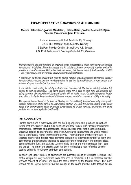
HEAT REFLECTIVE COATINGS OF ALUMINIUM<strong>Merete</strong> <strong>Hallenstvet</strong> 1 , Jostein Mårdalen 2 , Helene Bolm 3 , Volker Rekowski 4 , BjørnSteinar Tanem 2 and John Erik Lein 21 Hydro <strong>Aluminium</strong> Rolled Products AS, Norway2 SINTEF Materials and Chemistry, Norway3 DuPont Powder Coatings Scandinavia AB, Sweden4 DuPont Performance Coatings GmbH & Co, GermanyThermal emissivity and solar reflectance are important surface characteristics to obtain energy-savings and increasedthermal comfort in buildings. <strong>Aluminium</strong> products used for building applications are normally coated or anodised forprotection and visual appearance. Both surface treatments give very high thermal emissivity levels, typically e = 0.85– 0.9. High emissivity levels are normally unfavourable for building applications.A coating with low thermal emissivity will reflect the thermal radiation indoors and decrease the heat loss caused bythermal irradiation outdoors, and thus contribute to reduce the total heat loss in cold climates. In warm climates a lowemissive coating can reduce the heat flow into a building.A low emissive powder coating for building applications has been developed. The thermal emissivity is below 0.5,reducing the heat loss considerably. This patent pending coating [1] is based on small flake-like conducting nonleafingaluminium pigments positioned close to and parallel with the coating surface. Controlling the pigment locationis crucial for obtaining the low emissivity and at the same time good chemical and mechanical stability of the coating.The degree of thermal insulation (in terms of U-values) can be considerably improved when using coatings withoptimised reflectivity in selected parts of the electromagnetic spectrum [2]. Using this new low emissive powder coatinginstead of an ordinary powder coating or anodised surface reduces the U-value from 3.07 to 2.40 W/m 2 K for oneparticular window frame application (Wicline 65).INTRODUCTIONPainted aluminium is extensively used for building applications in products as roof andfacade sections, shutters and blinds, door and window frames. The excellent mechanical,chemical (i.e. corrosion and degradation) and aesthetical properties makes aluminiumattractive despite its poor thermal properties. Compared to polymers and wood, metalshave a significantly higher thermal conductivity. Thermal brakes are therefore used toseparate exterior and interior metal elements in buildings. Thermal control of window anddoor frames are particularly challenging because of their functionality (holding the glass,opening/closing function, etc) and size (normally thinner and more compact than roofsand walls). The aim of the present work has been to develop a heat reflective powdercoating primarily for window and door applications.Window and door frames of aluminium are normally made of extruded sections. Theprofile design will vary somewhat from producer to producer, but it is common that thesections consist of an inner- and an outer part separated by the thermal brakes. The innersection has an interior surface facing the interior of the room and the outer section has an
exterior surface facing the exterior. The outer surface of the inner section and the innersurface of the outer section are normally facing each other. If so, these internal surfaces canexchange energy by radiation.In general there are three mechanisms for heat transport; thermal conduction, convection and,and thermal radiation. In aluminium frames with proper application of thermal breaks, up to65% of the remaining heat transfer through the frame is caused by thermal radiation betweenthe inner and outer sections. A further improvement of the thermal characteristics of thealuminium frame thus requires minimisation of irradiative heat transfer losses. The heattransfer caused by thermal radiation is governed by the thermal emittance properties of thesection surfaces. To reduce thermal heat transfer in windows and doors it is especiallyimportant that the thermal emittance of the internal and interior surfaces is kept as low aspossible. The emittance of the exterior surface is of less importance due to its larger heattransfer by convection.Thermally low emissive surfaces can, among others, be made by adding aluminium flakepigments to a powder coating. The principal idea of the present work is to utilize the highreflectivity of the aluminium flakes in the thermal range of the spectrum (2-50 µmwavelengths) to obtain low emissivity. Since polymers are absorbing heavily in thiswavelength range it is crucial to obtain a high lateral coverage of the surface by thealuminium flakes, to ensure that the flakes are located near the outer surface of the coating,and that they are aligned parallel to it.Unfortunately a high aluminium pigment concentration at or close to the coating surfacewill cause the coating to be less chemically stable and more susceptible for corrosion andchemical degradation. An important task for making a resistant low emissivity coating istherefore to balance between the requirements for low emissivity and chemical stability.EXPERIMENTALThe powder coating systems used in this study is based on a polyester binder systemcontaining commercially available aluminium flake pigments. The pigments are mixed withthe rest of the coating chemicals using standard extrusion or bonding processes.Application of the coatings has been done by both handheld (lab) and automatedelectrostatic powder guns in line using a Gema Optitronic Type CG03. Applying powderscontaining large amounts of metallic pigments require fine tuning of powder coatingequipment because the polymer particles are difficult to charge. The powder is cured at 10minutes @ 200°C in a standard convection oven.Chemical resistance of coated samples is measured simply by dipping the coated samples in10% w/w HCl for 8h. This exposure corresponds to 1000 h in an acidified salt spray test(ASS) following the ASTM G85-94 standard, for the types of samples in question.The degree of chemical degradation is determined by using the L-value from standardcolour measurements. The L-value is used as a quantitative measure of how much visiblelight a surface will reflect. Degradation of a surface will normally result in a decrease in themeasured L-value, i.e. the surface becomes darker. A reduction in L-value by 1 percentagepoint is normally not visible for our eyes.
Thermal emissivity is calculated from IR reflectivity measurement in the wavelength range2 – 25 µm using the Planck spectrum of a thermal (300 K) black body as the weightingfunction. The IR reflectivity data are measured using a Bruker FTIR IFS 55 integratingsphere.A Philips CM-30 TEM equipped with an X-ray EDS analytical system was used for crosssectionalexamination of coatings and pigments. The coated samples were embedded inepoxy in order to support the coating. Cross section samples for TEM analyses were madeby cutting thin foils of the embedded samples using a Reichert-Jung ultra microtome. Finalsectioning was performed with a MicroStar diamond knife.The heat loss through a window frame is measured in controlled climate chambersaccording to EN 12412-2. The window frame profiles are separating two chambers; onesimulating the interior of a room with constant temperature 20°C, and the other simulatingthe exterior side with constant temperature 0°C. The U-values are calculated from theheating required in the warm zone to maintain constant temperature at 20°C.Heat loss (U-value) calculations are based on the profile shape and the thermal emissivityof the surfaces of them, and are done in accordance with EN 10077-2.RESULTS AND DISCUSSIONPigment concentration and the comparison of extrusion and bondingIn order to have the highest possible IR reflectivity it is important to bond as muchmetallic pigment flakes as possible. The single most important factor for making a low-ecoating is the pigment addition level. Figure 4 show how the reflectance of thermalradiation vary with the pigment addition level and how different the reflectance is forextruded and bonded pigments. The thermal emissivities fond in table 1 are calculatedfrom the reflectance curves of figure 1.It is obvious that increasing pigment concentration will reduce the thermal emissivity. Thisis the case both for extrusion and bonding. It is also evident that the bonding process is givingcoatings with high thermal reflectivity (= low-e), whereas extruded coatings does not workfor our purpose.
chemical protection without absorbing too much thermal radiation. Investigation oforganic coatings on pure aluminium substrates show that the optimum thickness of anorganic protective layer is 0.5 – 2 µm. A thinner layer will not protect the aluminiumpigments from degrading and a thicker layer will absorb too much IR radiation. Thechallenge is then to make an aluminium metallic pigmented powder coating allowingsuitable protection for the underlying aluminium substrate, and at the same time optimisethe aluminium pigment location for low emissivity and chemical stability.There are three main methods for mixing metallic pigments in powder coatings. Blending ofpolymer particles and metallic pigments is the simplest, but it is not well suited forindustrial application because of phase separation during transport, handling andapplication. Extrusion is extensively used in the powder coating industry to avoid the phaseseparation. Polymer and metallic pigments are mixed, melted and blended in an extrudermachine. During extrusion the metallic pigments will be evenly distributed inside thepolymer powder particles. The final cured coating will therefore have the metallic flakeparticles distributed in a randomized manner within the coating. This is not ideal in ourcase where a positioning of the aluminium pigment close to the surface is the aim. Pigmentparticles within the “bulk” of the cured coating will have a very limited effect on thethermal emissivity. This explains the poor emissivity results of the extruded coating infigure 1 and table 1.The last pigment mixing technique is bonding. The metallic flakes are attached to thepolymer particles through a heating procedure. The polymer particles are heated to atemperature where they are getting sticky, but not yet melted, and the metallic pigmentflakes are attached to the polymer particles. Polymer and metal particles can after bondingnot be separated. Bonded metallic pigment flakes are located at the polymer particlesurface, and normally oriented with their flat side attached to it (figure 2). At a certainpigment concentration level, there is no more room for pigment flakes to be attached tothe polymer particles, a saturation level is reached. The polymer particle showed in figure 2(right side) has reached its saturation level.High pigment concentrations result in difficulties of applying (spraying) the powder coatingonto an object. Such problems are caused by poor electrostatic charging of polymerparticles covered with too much metal flakes.For the purpose of making a low emissive coating bonding is preferred to extrusion becauseof the localization of the aluminium pigment flakes. When a bonded powder is melted andcured, the pigments will be positioned at the “grain boundaries” of the polymer particlesand at the surface (figure 3 and 4). The metal flake pigment particles are seen on edge. Inthe optical image the unfocused white features are pigments more or less on their flat sidelocalized at a grain boundary somewhat embedded in the sample. The TEM samples on theother hand, are so thin that it is unlikely to find pigments laying flat.
2 % 6 %Figure 2 SEM image (secondary electrons) of aluminium flakes bonded to the polymer particles. Thepigment flakes are all attached to the polymer particle by their flat side. The two images show two differentpigment concentrations (2%and 6%) indicating that there is no space for bonding more than a certainpercentage of metal pigments to the polymer powder. Excess pigment will probably not be bonded.Figure 3 Cross section optical micrograph of a bonded coating showing how the metallic pigments are locatedat the boundaries between what were polymer grains before melting and curing. The white unfocused featuresin the image are metal pigments underneath the prepared surface.
Powder coatingAl-pigmentEmbeddingFigure 4 The aluminium flake pigments close to the coating surface are oriented parallel to it (left) and havea more random orientation following the polymer grain boundaries in bulk coating (right). The surfacepigments are typically located around 1 µm underneath the top surface of the coating. The interface betweenthe embedding epoxy and the coating is located at the tip of the black arrow (left)In figure 4 (left) it is shown how the metal pigments are aligning parallel to the coatingsurface. From an emissivity point of view this is ideal. In order to protect the pigmentsfrom degradation, the pigment should be embedded in the polymer. The optimum pigmentdepth is a trade-off between chemical protection and IR reflection as stated above. Thesample in figure 4 (right) show a pigment location typically around 1 µm under the coatingsurface. This is a very good compromise. During the melting – curing process of thepowder coating the pigments are “moved” from a position at the polymer particle surfaceto a position right underneath the cured coating surface. This is obtained by a combination ofpolymer properties and process conditions.Pigment coatingIn order to prevent chemical degradation it is required but not sufficient that the pigmentsare localised somewhat underneath the coating surface. In addition the pigments need to becovered by a protective layer. Organic pigment coatings (e.g. acryl) are common, but ourmeasurements (not reported here) show that they will be too absorbent of thermal IR andtherefore not suitable for low emissive coatings. Silica is a common inorganic pigmentcoating. It is less absorbent in the thermal IR and more suitable for low emissive coatingsthan acryl. Recently, aluminium pigments have also been encapsulated with silica using solgeltechniques [3].Figure 5 shows TEM images of cross sections of single pigment flakes localized in a curedpowder coating. Four different pigments, all coated with silicon oxide are compared.Powder coatings containing these pigments have been tested for chemical resistance by theHCl dip test. The results are summarised in table 2.
ABCDFigure 5 Cross section TEM images of powder coatings containing four different silicon oxide coatedpigments. Large variation of the pigment coating is foundPigment C fails completely in the chemical resistance test. A change in the L-value of -23represents a considerable darkening caused by aluminium pigment degradation. The reasonfor this degradation is linked to the very poor and “fluffy” silicon oxide pigment coatinglayer shown in figure 5C. The pigment coating seems to be either very porous or it hasbeen dissolved in the powder coating binder.Pigment D has a dense silicon oxide layer encapsulating the pigments, but the coverage isincomplete. This result in a ? L of -2.33 after the chemical degradation test, considerablybetter than pigment C, but not as good as A and B.Pigments A and B have a continuous silicon oxide coating of the pigments. This gives avery good chemical resistance. A ? L value of about -1.0 is normally not visible. Thesepigments also give a low thermal emissivity (slightly below 0.5). Pigment B has been chosenfor the industrialized version of the low emissive powder coating. Its combination of lowemissivity and good chemical stability makes it well suited for the purpose.
Table 2 Comparison of emissivity and chemical stability data for the four different aluminium pigmentsshown in figure 5. A close relation between the silicon oxide coating quality and the chemical resistance ofthe powder coating is foundPigment Emissivitye? L after 8h in10% HClChemicalresistancePigment coatingthickness [nm]A 0.49 - 1.09 very good 10 - 30B 0.48 - 1.02 very good ~ 10C 0.47 - 23 poor No continuous pigmentcoating, dissolved SiO 2 ?D 0.45 - 2.33 OK (?) ~ 20, only partly coatedpigmentU-value calculation and measurementsThe obtained reduction in thermal emissivity from 0.9 to about 0.5 will result inconsiderable energy savings. U-value calculations and measurements have been done usinga Wicline 65 window profile. The results are given in table 3.Table 3 Calculated and measured heat loss in terms of U-values for a Wicline 65 window profile withdifferent emissivity of the powder coatingsEmissivity 0.9 Emissivity 0.5Calculations EN 10077-2 3.01 W/m 2 K 2.43 W/m 2 KMeasurements EN 12412-2 3.07 W/m 2 K 2.40 W/m 2 KThere is an excellent agreement between measured and calculated U-values. It is furthershown that the reduced emissivity of the coating is reducing the heat loss through thewindow frame from 3.07 to 2.40 W/m 2 K, a reduction by more than 20% The part of theheat loss caused by radiation is considerable. The use of this low emissive coating willreduce the energy consumption in buildings correspondingly.CONCLUSIONSA powder coating with heat reflective properties has been developed. The thermalemissivity is slightly below 0.5. This represent a considerable potential for energy savingswhen used for building applications compared to the use of ordinary powder coatings with
typical emissivity 0.85 – 0.9. The heat loss from Wicline 65 window frames is reduced from3.07 to 2.40 W/ m 2 K. This measured value is confirmed by calculations.Non leafing aluminium metallic flake pigments are used in order to obtain a high IRreflectivity (= low thermal emissivity). The pigments must be bonded to the powdercoating polymer particles at the highest possible concentration, and their location in thecoating is crucial for obtaining low emissivity and a sufficient chemical stability at the sametime. Extrusion of the pigments is not working due to the random localisation of thepigment in the cured coating.The chemical stability is also depending on the coating of the pigments. Inorganic oxidesare preferred for pigment coating because of the low IR absorption. Some silica coatedpigments give a chemically resistant film. These pigments are characterised by a silicacoating 10 – 30 nm thick that completely covers the metal pigment flakes.TEM analysis of cross sections is a powerful tool for investigating the pigments, theirlocation and the quality of their coating.ACKNOWLEDGEMENTSThermal reflectivity measurements have carefully been performed by T. Hallberg at FOI inLinköping, Sweden. Calculations and measurements of U-values have cautiously beenperformed by Institut für Fenster Technique in Rosenheim, Germany.This work is a part of the Heat Reflecting Coating project financially supported by theNorwegian Research Council.REFERENCES1. Helene Bolm, Volker Rekowski, Tom E. Jeffers, <strong>Merete</strong> <strong>Hallenstvet</strong>, and JosteinMårdalen: “Low emissive powder coating” Filed patent application, 05P021 - FA1459US PRV.2. <strong>Merete</strong> <strong>Hallenstvet</strong>, Werner Jager, Eberhard Ackermann, Tore Kolås, CornelisSpooren, Jostein Mårdalen, “Structural metal element with improved thermal propertiesand a method for making same”, Filed patent application, P04028PCT.3. Ulrich-Andreas Hirth: “<strong>Aluminium</strong> Pigments for Powder coating Applications” PaperV.3 from the 8 th Nürnberg Congress 2005.