

Instruction Manual - TECO-Westinghouse Motor Company
Instruction Manual - TECO-Westinghouse Motor Company
Instruction Manual - TECO-Westinghouse Motor Company

You also want an ePaper? Increase the reach of your titles
YUMPU automatically turns print PDFs into web optimized ePapers that Google loves.
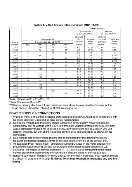
TABLE 1. V-Belt Sheave Pitch Diameters (MG1-14.42)Horsepower atFrameSynchronous Speed, RPMNumber 3600 1800 1200 900ConventionalA, B, C, D AND EMinimumPitchDiameterInchesV-Belt Sheave*MaximumWidthInchesNarrow3V, 5V, AND 8VMinimumOutsideDiameterInches**MaximumWidthInches324T ... 40 25 20 6.0 10.25 6.0 5.25326T ... 50 30 25 6.8 10.25 6.8 5.25364T ... ... 40 30 6.8 11.5 6.8 5364T ... 60 ... ... 7.4 11.5 7.4 5.785365T ... ... 50 40 8.2 11.5 8.2 5.785365T ... 75 ... ... 9.0 11.5 8.6 5.785404T ... ... 60 ... 9.0 14.25 8.0 7.25404T ... ... ... 50 9.0 14.25 8.4 7.25404T ... 100 ... ... 10.0 14.25 8.6 7.25405T ... ... 75 60 10.0 14.25 10.0 7.25405T ... 100 ... ... 10.0 14.25 8.6 7.25405T ... 125 ... ... 11.5 14.25 10.5 7.25444T ... ... 100 ... 11.0 16.75 10.0 8.5444T ... ... ... 75 10.5 16.75 9.5 8.5444T ... 125 ... ... 11.0 16.75 9.5 8.5444T ... 150 ... ... ... 16.75 10.5 8.5445T ... ... 125 ... 12.5 16.75 12.0 8.5445T ... ... ... 100 12.5 16.75 12.0 8.5445T ... 150 ... ... ... 16.75 10.5 8.5*Max. Sheave width = 2(N-W) - .25**Max Sheave width = N-W***Sheave ratios grater than 5:1 and center-to-center distance less than the diameter of thelarge sheave should be referred to <strong>TECO</strong>-<strong>Westinghouse</strong>.POWER SUPPLY & CONNECTIONS1. Wiring of motor and control, overload protection and grounding should be in accordance withNational Electrical Code and all local safety requirements.2. Nameplate voltage and frequency should agree with power supply. <strong>Motor</strong> will operatesatisfactorily on line voltage within ±10% of nameplate voltage; or frequency with ±5% andwith a combined variation not to exceed ±10%. 230-volt motors can be used on 208-voltnetwork systems, but with slightly modified performance characteristics as shown on thenameplate.3. Dual voltage and single voltage motors can be connected for the desired voltage byfollowing connection diagram shown on the nameplate or inside of the conduit box.4. All Explosion Proof motors have Temperature Limiting Devices in the motor enclosure toprevent excessive external surface temperature of the motor in accordance with U/Lstandards. Terminals of thermal protectors (P1 & P2) should be connected to the motorcontrol equipment, according to the connection diagram inside of the conduit box.5. Standard connection diagram for three phase, not thermally protected, dual rotation motorsare shown in diagrams A through E. (Note: To change rotation, Interchange any two lineleads)


