Restoration of an Eddystone S.750 - The section you are trying to ...
Restoration of an Eddystone S.750 - The section you are trying to ...
Restoration of an Eddystone S.750 - The section you are trying to ...
Create successful ePaper yourself
Turn your PDF publications into a flip-book with our unique Google optimized e-Paper software.
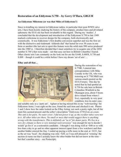
<strong>Res<strong>to</strong>ration</strong> <strong>of</strong> <strong>an</strong> <strong>Eddys<strong>to</strong>ne</strong> <strong>S.750</strong> – by Gerry O’Hara, G8GUHAn <strong>Eddys<strong>to</strong>ne</strong> Miles<strong>to</strong>ne (or was that Miles <strong>of</strong> <strong>Eddys<strong>to</strong>ne</strong>?)Since re-kindling my interest in <strong>Eddys<strong>to</strong>ne</strong> radios, in particular their post-WWII valvesets, I have been keenly studying the his<strong>to</strong>ry <strong>of</strong> the comp<strong>an</strong>y, product lines <strong>an</strong>d all relatedephemera: the EUG site has been invaluable in this regard. During my ‘studies’, Iconcluded that the development <strong>an</strong>d introduction <strong>of</strong> the <strong>Eddys<strong>to</strong>ne</strong> <strong>S.750</strong> in late 1949marked a miles<strong>to</strong>ne in receiver design for the comp<strong>an</strong>y, both electronically <strong>an</strong>dcosmetically. It was <strong>Eddys<strong>to</strong>ne</strong>’s first double-conversion superhet <strong>an</strong>d was the first setwith the distinctive <strong>an</strong>d trademark ‘sliderule dial’ that lasted for over 30 years in oneform or <strong>an</strong>other (the last sets <strong>to</strong> sport this feature were the solid state 990 series producedin<strong>to</strong> the 1980’s). I therefore decided that I must somehow try <strong>to</strong> acquire one <strong>of</strong> the 2054number <strong>S.750</strong>’s that were made – not that easy out here in British Columbia I fe<strong>are</strong>d.Other classic sets I am const<strong>an</strong>tly on the look out for <strong>are</strong> the S.640, S.680X, S.730 <strong>an</strong>dS.888 – though it could be a while before I have my dream ‘set <strong>of</strong> sets’…EBay <strong>an</strong>d all that…During the res<strong>to</strong>ration <strong>of</strong> myS.770R, I entered in<strong>to</strong>correspondence with MikeCassidy in the UK, who wasres<strong>to</strong>ring <strong>an</strong> S.770UMkII (seevarious emails posted on theEUG Forum). One day henoted that he had spotted <strong>an</strong><strong>S.750</strong> for sale here in BritishColumbia (Winfield in theOk<strong>an</strong>ag<strong>an</strong> <strong>are</strong>a, about 5 hoursdrive inl<strong>an</strong>d from where I1live), reportedly in very poorcondition, less its outer case,<strong>an</strong>d suitable only as a ‘parts set’. Aghast at having missed this in my ‘web-trawling’ for<strong>Eddys<strong>to</strong>ne</strong> items, I was right on the case, found the said item <strong>an</strong>d checked it out. Pho<strong>to</strong>s1 <strong>an</strong>d 2 show how the radio looked on the EBay listing: not such a pretty sight, but all themain bits seemed present <strong>an</strong>d the seller’s description “<strong>Eddys<strong>to</strong>ne</strong> S750 from <strong>an</strong> estate.This unit is for parts. No outer cover. I did not power it up, as the rectifier tubes were notin it. All other tubes <strong>are</strong> there. No smell or mess that would suggest there is <strong>an</strong>ythingwrong with the tr<strong>an</strong>sformers. This is definitely <strong>an</strong> "as is" for donor parts. We live in avery dry climate so there is very minimal rust/corrosion” was enough for me <strong>to</strong> decide Iwould ‘go for it’ as a res<strong>to</strong>ration c<strong>an</strong>didate. I thought I was doing well at ~$40 or so withless th<strong>an</strong> a day <strong>to</strong> go <strong>an</strong>d no other app<strong>are</strong>nt interest (apart from a few watchers) <strong>an</strong>d then<strong>an</strong>other bidder entered the fray: I ended up paying a trifle more in the end, at ~$121, butas the set was ‘local’, the shipping was only ~$20, so I was still pleased at ‘winning’ theauction (it turns out that I actually knew the other bidder but did not know at the time –but that’s <strong>an</strong>other s<strong>to</strong>ry – see Postscript).1
So, once again, I thought the s<strong>to</strong>ry <strong>of</strong> res<strong>to</strong>ring this classic <strong>Eddys<strong>to</strong>ne</strong> radio <strong>to</strong> its formerglory might be <strong>of</strong> some interest <strong>to</strong> EUG folks. As previously, I have kept the descriptionin brief ‘bullet’ form as I find this is easier for folks <strong>to</strong> digest <strong>an</strong>d have added plenty <strong>of</strong>pho<strong>to</strong>s <strong>to</strong> help visualize the process. In particular, I have included a very detaileddescription <strong>an</strong>d several pho<strong>to</strong>s <strong>of</strong> the disassembly/reassembly <strong>of</strong> the front p<strong>an</strong>el/drivemech<strong>an</strong>ism, plus some tips on this process, such that I hope that it will assist others intackling what could be a rather daunting task with those niggling questions in the back <strong>of</strong><strong>you</strong>r mind as <strong>to</strong> whether it will all go back <strong>to</strong>gether?, will it ever work again? <strong>an</strong>d wha<strong>to</strong>n earth the left-over parts were needed for once the thing is re-assembled?...(!)Preliminary Inspection <strong>an</strong>d Basic Preparation2On arrival (very promptlymay I add <strong>to</strong> the seller’scredit), the radio had beenwell packed in bubblewrap<strong>an</strong>d a s<strong>to</strong>utcardboard box <strong>an</strong>d hadtraveled well, apart fromthe N78 output valvehaving come loose in thebox <strong>an</strong>d with badly bentpins. However, the radioactually looked worse ‘inthe flesh’ th<strong>an</strong> on theEBay listing (pho<strong>to</strong>s 3, 4<strong>an</strong>d 6), though a preliminary inspection revealed that with the exception <strong>of</strong> the rectifier<strong>an</strong>d stabilizer valves (<strong>an</strong>d obviously the case) all the main bits were indeed present <strong>an</strong>d,apart from a dented ‘inner h<strong>an</strong>dle’ (the metal bars that wrap around from one frontchrome-plated grab h<strong>an</strong>dle bolt <strong>to</strong> the other), possibly indicating it had been dropped orhit at some point in its 56 year his<strong>to</strong>ry, no obvious mech<strong>an</strong>ical damage (note: I have nowconcluded that‘dropping <strong>Eddys<strong>to</strong>ne</strong>s’must be a world sport <strong>of</strong>some kind, with thecontest<strong>an</strong>ts eithersimply curious as <strong>to</strong>what happens when+40lbs <strong>of</strong> British metal,glass <strong>an</strong>d electronicshits the ground <strong>an</strong>d/orwhether the <strong>Eddys<strong>to</strong>ne</strong>reputation forrobustness will stayintact even when hit by32
a baseball bat). Worse, it was obvious that a former owner had sprayed the front p<strong>an</strong>el amedium-grey colour (the original black crackle showing through in parts) <strong>an</strong>d,unfortunately, had done this with the front p<strong>an</strong>el still on the receiver with a minimalamount <strong>of</strong> masking: consequently most <strong>of</strong> theinnards <strong>of</strong> the radio had been sprayed as well– wiring looms, chassis parts, front <strong>of</strong> themains tr<strong>an</strong>sformer, parts <strong>of</strong> the IF c<strong>an</strong>s,resis<strong>to</strong>rs, capaci<strong>to</strong>rs etc, even the <strong>to</strong>p <strong>of</strong> thetrimmers in the coil box – what a mess! Oncloser inspection, I noticed that one <strong>of</strong> the dialbulb holders was <strong>an</strong> incorrect type (screwbase) that had been ‘encouraged’ <strong>to</strong> fit withplenty <strong>of</strong> insulation tape <strong>an</strong>d some ‘hockeytape’ for good measure (this being C<strong>an</strong>ada,what else?), <strong>an</strong>d it looked like it had shortedout <strong>to</strong> chassis a few times. <strong>The</strong> tuningmech<strong>an</strong>ism, rather th<strong>an</strong> having that silkysmooth <strong>Eddys<strong>to</strong>ne</strong> feel, was almost <strong>to</strong>tallystuck, <strong>an</strong>d when it was turned (forced), Inoticed that the tuning g<strong>an</strong>g was not moving.Examination revealed that this was due <strong>to</strong> the‘ratio arm’ mech<strong>an</strong>ism being missing. Thisshould comprise two small springs attached <strong>to</strong>a cr<strong>an</strong>k on the end <strong>of</strong> the tuning g<strong>an</strong>g, holding a spring-wire loop in place that retains thecr<strong>an</strong>k against a small ‘boss’ located eccentrically on one <strong>of</strong> the tuning mech<strong>an</strong>ism gears(pho<strong>to</strong>s 6 <strong>an</strong>d 21). However, peering in<strong>to</strong> the grime very closely in this <strong>are</strong>a <strong>of</strong> thechassis revealed that the spring-wire loop was laying on the chassis, retained by fluff <strong>an</strong>ddead spiders, but only one spring was found <strong>to</strong> be still affixed <strong>to</strong> the tuning capaci<strong>to</strong>rcr<strong>an</strong>k arm. <strong>The</strong> ratio arm is a clever little device that ‘linearizes’ the otherwise non-linearreadout on the sliderule dial – the ratio arm was one <strong>of</strong> Bill Cooke’s pet inventions, <strong>an</strong>drightly so – simple yet very effective (page 12 <strong>of</strong> ‘<strong>The</strong> Cooke Report’ on the EUG site).<strong>The</strong> serial number <strong>of</strong> the set(pho<strong>to</strong> 5), GB0355, indicatedthat the set was either made inJuly, 1950, according <strong>to</strong> myinterpretation <strong>of</strong> the serialnumber information on Al<strong>an</strong>Clay<strong>to</strong>n’s <strong>Eddys<strong>to</strong>ne</strong> website(www.qsl.net/eddys<strong>to</strong>ne,5though this site is currentlydown <strong>an</strong>d under revision), orFebruary, 1955, according <strong>to</strong>the EUG Quick Reference Guide (QRG), page 26 (always assuming the letters werestamped the correct way around in the first place! – app<strong>are</strong>ntly not always the case). Isuspect it was the earlier <strong>of</strong> these two possible dates <strong>an</strong>d my set was probably from one <strong>of</strong>43
the first <strong>S.750</strong> production runs at the Bath Tub. This conclusion is supported by a date <strong>of</strong>‘Nov. 1947’ on the electrolytic capaci<strong>to</strong>r c<strong>an</strong>s as I would doubt that <strong>Eddys<strong>to</strong>ne</strong> wereusing eight year old s<strong>to</strong>ck? Also, C85 is present across the output tr<strong>an</strong>sformer primary -noted <strong>to</strong> be so only on early models by Ted Moore in ‘Lighthouse’ - <strong>an</strong>d there was nosign <strong>of</strong> the set having ever sported a cover over the tuning g<strong>an</strong>g, a refinement that waslikely introduced later in the production run (<strong>an</strong> illustration in a [1949?] ‘preview’catalogue entry #T1315 shows <strong>an</strong> <strong>S.750</strong> chassis without this cover, noting that“production commences early 1950”).So, I placed the <strong>S.750</strong> on myworkbench, found thevacuum cle<strong>an</strong>er, a digitalcamera, made a cup <strong>of</strong> tea(essential for hum<strong>an</strong>lubrication <strong>an</strong>d brain functionwhen dealing with radioequipment – a tip fromGordon m<strong>an</strong>y moons ago),rolled my sleeves up, <strong>to</strong>ok adeep breath <strong>an</strong>d…6- Removed the valves,cle<strong>an</strong>ed the glass <strong>an</strong>d pins<strong>an</strong>d s<strong>to</strong>red them away. Thatwas easy… then I thought Imight as well test them while I was at it (see ‘Valve Testing’ sidebar on next page) – twobad 6BA6’s <strong>an</strong>d a bad 6AT6. Luckily I had replacements in s<strong>to</strong>ck, along with aVR150/30, but no 5Z4G - that was later obtained from the local ‘club’ (Society for thePreservation <strong>of</strong> Antique Radio in C<strong>an</strong>ada, SPARC), well, almost, a 5Z4 – metal casevariety – that would do for now <strong>an</strong>yway until I obtain a glass bottle version.- Vacuum-cle<strong>an</strong>ed the chassis <strong>an</strong>d case, using the small paintbrush <strong>to</strong> penetrate nooks <strong>an</strong>dcr<strong>an</strong>nies – it had been home <strong>to</strong>generations <strong>of</strong> spiders from theOk<strong>an</strong>ag<strong>an</strong>, who had notbothered <strong>to</strong> bury their dead butinstead hung them oncomponent wires for show. Ablast <strong>of</strong> air from mycompressor cle<strong>an</strong>ed out thetuning capaci<strong>to</strong>r v<strong>an</strong>es. Fornow, I wiped the front p<strong>an</strong>elwith cot<strong>to</strong>n wool wipes <strong>an</strong>dwarm soapy water <strong>an</strong>d workedon the chassis with isopropylalcohol (using Q-tips <strong>an</strong>dcloths) <strong>to</strong> remove the74
is not <strong>to</strong>o bad, with only a slight <strong>are</strong>a <strong>of</strong> wear <strong>to</strong> the <strong>to</strong>p left <strong>of</strong> the tuning knob.Removing <strong>an</strong>d Replacing the Front P<strong>an</strong>el <strong>an</strong>d Drive Mech<strong>an</strong>ism- I <strong>to</strong>ok several pho<strong>to</strong>s <strong>of</strong> the tuning drive mech<strong>an</strong>ism from all <strong>an</strong>gles for reference. <strong>The</strong>drive cord looked in reasonable condition, so I decided <strong>to</strong> leave it fixed <strong>to</strong> the spoolpulleys at either end <strong>an</strong>d remove them <strong>an</strong>d the cord intact – hoping that I would not have<strong>to</strong> re-string the dial (see EUG Newsletter #25, p17 for tips on this if <strong>you</strong> have <strong>to</strong> do it).9- Removed the front-most spacing bushings from between the side chassis members <strong>an</strong>dthe internal ‘h<strong>an</strong>dles’, allowing the lower outer front p<strong>an</strong>el retaining bolts <strong>to</strong> be easilyremoved. Removed the upper outer front p<strong>an</strong>el retaining bolts <strong>an</strong>d <strong>to</strong>ok the chromeh<strong>an</strong>dles away. Removed the four inner front p<strong>an</strong>el retaining bolts (these <strong>are</strong> removedfrom the front <strong>an</strong>d <strong>are</strong> exposed once the finger plate is <strong>of</strong>f). Pulled the front p<strong>an</strong>el castingaway, complete with the dial drive mech<strong>an</strong>ism (pho<strong>to</strong> 10). If the ratio arm mech<strong>an</strong>ismwas intact, c<strong>are</strong> would need <strong>to</strong> be exercised at this point <strong>to</strong> extract the boss from the cr<strong>an</strong>karm (probably pulling the springs <strong>an</strong>d taking the spring wire loop <strong>of</strong>f its hook).10- With some difficulty, due <strong>to</strong> the mech<strong>an</strong>ism being very stiff, I approximately centeredthe drive <strong>an</strong>d prevented the cord from leaving its grooves on the spool pulleys using two6
small pieces <strong>of</strong> masking tape (pho<strong>to</strong> 11). C<strong>are</strong>ful inspection <strong>of</strong> the gearbox revealed thatnothing was binding or blocking movement <strong>of</strong> the gears <strong>an</strong>d that the stiffness was due <strong>to</strong>gummed-up bearings <strong>an</strong>d teeth (age-solidified 3-in-One oil I would say) <strong>an</strong>d, apart fromsome wear on the brass gears, the only damage noted was that a <strong>to</strong>oth on each <strong>of</strong> thespool pulley gears was damaged (pho<strong>to</strong> 12).- Removed the spring-loaded idler (cord tension) pulley by loosening the pivot screwfixing it <strong>to</strong> the front p<strong>an</strong>el casting, loosened the three screws holding the gearbox <strong>to</strong> thefront p<strong>an</strong>el casting, tipped it forwards <strong>an</strong>d upwards slightly <strong>an</strong>d then eased the drive cordaway from the upper two idler pulleys. <strong>The</strong> gearbox was then removed with the dial cordintact (pho<strong>to</strong> 11).11- Removed the dial plate (four screws) <strong>an</strong>dthe dial glass (four screws). Pulled thetuning knob spindle out <strong>of</strong> its bushing.12- Removed the upper idler pulleys <strong>an</strong>d rearpointer guide bar by removing their screwsfrom the front p<strong>an</strong>el casting. <strong>The</strong> frontguide bar is retained by the rear barbrackets, but sits in a red masticcompound. Removed the all-import<strong>an</strong>t7
<strong>Eddys<strong>to</strong>ne</strong> logo (pho<strong>to</strong> 13) by unscrewing its small retaining plate <strong>an</strong>d, finally removedthe tuning drive bushing from the front p<strong>an</strong>el casting. All the component parts <strong>are</strong> shownin pho<strong>to</strong> 14.13- I removed the loggingscale (vernier) dial platefrom the gearbox frontspindle <strong>an</strong>d placed thegearbox in<strong>to</strong> a smoothjawedbench vice <strong>an</strong>dthen painstakinglycle<strong>an</strong>ed each <strong>to</strong>oth oneach gear <strong>an</strong>d pinionusing isopropyl alcohol, adarning needle <strong>an</strong>d Q-tips. I used lighter fluid <strong>to</strong> remove the stubborn ‘gum’ <strong>an</strong>d cle<strong>an</strong>out the bearings (bushings). I found that the gears were now freely-turning <strong>an</strong>d I decidednot <strong>to</strong> dism<strong>an</strong>tle the gearbox <strong>to</strong>tally, but <strong>to</strong> apply a light coating <strong>of</strong> high-quality lightmachine oil (not 3-in-One!) <strong>to</strong> each <strong>of</strong> the bearings <strong>an</strong>d a smearing <strong>of</strong> molybdenum(‘moly’) grease <strong>to</strong> the parts <strong>of</strong> the brass gears that did not mesh with the plastic spoolpulleys. Tried it out - smooooth…. <strong>The</strong> friction drive plate was cle<strong>an</strong>ed using lighterfluid <strong>to</strong> remove <strong>an</strong>y stray oil or grease, as was its mating surface on the tuning spindle.- Cle<strong>an</strong>ed the dial plate <strong>an</strong>d vernier dial plate using warm soapy water <strong>an</strong>d cot<strong>to</strong>n wool –these have very delicate silk screen markings (so be very gentle) – pho<strong>to</strong> 15.- I decided that the grey front p<strong>an</strong>el should be re-finished in its original black crackle.One day I will probably have this s<strong>to</strong>ve enameled by a local paint shop, but for now I814
emembered that I had some blackcrackle finish spray paint left overfrom the S.740 S-Meter/Speakerproject. I cle<strong>an</strong>ed up the frontp<strong>an</strong>el using alcohol <strong>an</strong>d lightlybuffed the surface <strong>an</strong>d gave it threecoats <strong>of</strong> the paint (pho<strong>to</strong> 16).- Cle<strong>an</strong>ed-up all the remainingdrive components (idler pulleys,dial glass etc) <strong>an</strong>d re-assembled the15drive mech<strong>an</strong>ism <strong>to</strong> the front p<strong>an</strong>elcasting, simply reversing thedisassembly order (pho<strong>to</strong>s 17 <strong>an</strong>d18) – the finger plate temporarily held in place with a couple <strong>of</strong> strips <strong>of</strong> double-sidedsticky tape.16- <strong>The</strong> tuning knob shaft was coated with moly grease prior <strong>to</strong> installation in its bushing.<strong>The</strong> tuning knob was then temporarily fitted <strong>an</strong>d the completed assembly tested for thatsensual ‘<strong>Eddys<strong>to</strong>ne</strong> smoothness’ – yep, it was there in spades, beautiful! - the twodamaged spool pulley teeth did not seem <strong>to</strong> affect the movement – th<strong>an</strong>k goodness. Nowfor the electronics… temporarily ignored in my eagerness <strong>to</strong> see if I could at least make9
the set look ok <strong>an</strong>d work mech<strong>an</strong>ically. I suddenly had cold-flushes thinking negativethoughts like ‘what if the mains tr<strong>an</strong>sformer is duff?’....1718Safety Testing <strong>an</strong>d Preliminary Electronic <strong>Res<strong>to</strong>ration</strong>- I decided <strong>to</strong> start work on the electronics with the front p<strong>an</strong>el still removed from thechassis (pho<strong>to</strong> 19) as this made access <strong>to</strong> underneath the chassis front much easier: useful10
if one or more <strong>of</strong> the gain controls, BFO variable capaci<strong>to</strong>r or switches needed <strong>to</strong> bereplaced or serviced.- On arrival, themains tr<strong>an</strong>sformerhad a piece <strong>of</strong>b<strong>are</strong> wire shovedin<strong>to</strong> the 110vtapping socket. Ireplaced this withthe correct type <strong>of</strong>insulated jumper(for some reason Ihad one in myjunk box).19- Installed aquick-blow in-linemains fuse in thepsu compartment.Also, installed a 250mA slow-blow fuse in a chassis-mounted fuseholder wired in<strong>to</strong> themains tr<strong>an</strong>sformer secondary centre tap (it had a 3 amp fast blow installed on arrival).- Checked the general electrical safety <strong>of</strong> the psu unit – checking for loose wires, poorinsulation etc. Replaced a pair <strong>of</strong> wires who’s insulation had been heat-damaged by thestabilizer dropper resis<strong>to</strong>r <strong>an</strong>d re-dressed them <strong>to</strong> avoid it happening again.- Installed a new mains lead <strong>an</strong>d chassis grommet, using a plastic cable-tie <strong>to</strong> retain thelead.- I made a replacement dial lamp holder <strong>to</strong> replace the bodged screw-thread one <strong>an</strong>dreplaced the long-bulb #47 dial lamps (pretty st<strong>an</strong>dard in US <strong>an</strong>d C<strong>an</strong>ada radios) with thecorrect small globe-type bulbs (the long-bulb #47 lamps interfered with the drive cord).20- I noticed that both the AF <strong>an</strong>d IF gainpots were non-original components: the IFgain was a 10kohm linear carbon track unit<strong>an</strong>d needed <strong>to</strong> be replaced with a wirewound (ww) unit as it carries a small DCcurrent – carbon tracks don’t like that. A‘period’ Colvern ww pot was found in myjunk box (ex-Blue Streak I think) – ittested ok <strong>an</strong>d was fitted (pho<strong>to</strong> 20). <strong>The</strong>AF gain pot tested intermittent, as well ashaving a cracked front plate, so that wasalso replaced with <strong>an</strong>other ‘period’ unit11
(250kohm log pot), this time recovered from a defunct radio chassis <strong>an</strong>d cle<strong>an</strong>ed using‘De-oxit’. <strong>The</strong> RF gain pot looked original <strong>an</strong>d tested ok after cle<strong>an</strong>ing, <strong>an</strong>d all theswitches checked ok. <strong>The</strong> BFO variable capaci<strong>to</strong>r bushings were cle<strong>an</strong>ed with ‘De-oxit’.- <strong>The</strong>n I re-attached the front p<strong>an</strong>el <strong>to</strong> the chassis. This is easier said th<strong>an</strong> done, as gettingall the switches <strong>an</strong>d other controls in<strong>to</strong> the correct holes at the same time takes somedoing! Re-attach by reversing the disassembly routine, inserting the four centre boltsattaching the coilbox <strong>an</strong>d then the four bolts attaching the chrome h<strong>an</strong>dles, followed bythe spacers between the lower side chassis members<strong>an</strong>d the ‘internal h<strong>an</strong>dles’.- I cle<strong>an</strong>ed the main tuning capaci<strong>to</strong>r contact ‘fingers’using 'De-Oxit' on the ro<strong>to</strong>r contacts <strong>an</strong>d re-packed theball bearings with moly grease. Re-assembled the ratioarm (pho<strong>to</strong> 21), making two new retaining springs fromjunk box parts <strong>an</strong>d applied a little moly grease <strong>to</strong> thesliding surface <strong>of</strong> the cr<strong>an</strong>k arm.- Next, I re-fitted each <strong>of</strong> the control retaining nuts,taking c<strong>are</strong> not <strong>to</strong> gouge the fingerplate. I used a smallhome-made ‘washer’ <strong>to</strong> do this with a regular pair <strong>of</strong>pliers (pho<strong>to</strong> 8), but I believe that a purpose-made <strong>to</strong>olc<strong>an</strong> be obtained (or made) for the round switch nuts, asc<strong>an</strong> a large hex ‘nut runner’ for the pots <strong>an</strong>d BFOcapaci<strong>to</strong>r nuts – though I do not possess either. <strong>The</strong>protective washer c<strong>an</strong> be made out <strong>of</strong> paper (as shown)or plastic – a good choice is the thin, ‘non-stick’ <strong>an</strong>ddurable Teflon sheet sold for lining baking trays (myXYL is still wondering why ‘mice’ app<strong>are</strong>ntly chewedon it)… replaced the knobs <strong>an</strong>d the set was ready for a few basic power-on checks.21- With all valves still removed, I applied power <strong>to</strong> the set, slowly increasing <strong>to</strong> 117vthrough a variac. Checked the tr<strong>an</strong>sformer secondary voltages - all good – phew!- Time <strong>to</strong> find out if the set will work…Electronic Testing <strong>an</strong>d Repairs- Cle<strong>an</strong>ed up each <strong>of</strong> the valve sockets in the set, including the two octal sockets on therear, marked as ‘Vibra<strong>to</strong>r A/S-Meter’ <strong>an</strong>d ‘Vibra<strong>to</strong>r B’ on my set, using 'De-Oxit'.- Resist<strong>an</strong>ce checks on the psu filter capaci<strong>to</strong>rs (C81 <strong>an</strong>d C83) indicated almost shortcircuit,as did C60 (1 st AF <strong>an</strong>ode decoupler). I decided <strong>to</strong> try <strong>to</strong> re-form these rather th<strong>an</strong>install replacements (for authenticity) as I had for my S.740. <strong>The</strong> capaci<strong>to</strong>rs were reformedover a day by slowly increasing voltage from the variac, moni<strong>to</strong>ring the HTcurrent draw (all valves still removed except the 5Z4 rectifier) - increasing the voltage in12
1000 ohms/volt Meter Switchboxstages, holding for up <strong>to</strong> <strong>an</strong> hour <strong>an</strong>d also switching<strong>of</strong>f/on a couple <strong>of</strong> times at each stage. As current drawfell <strong>of</strong>f at each voltage increment, I increase the appliedvoltage by 25v, up <strong>to</strong> the full HT volts <strong>of</strong> ~250v.Leakage current at the end <strong>of</strong> re-forming wasacceptably low on all capaci<strong>to</strong>rs – quite amazing for 59year old units.In my S.770R res<strong>to</strong>ration article, Idescribed a simple gadget <strong>to</strong> convert a‘modern’ 20kohms/volt meter in<strong>to</strong> a1000ohms/volt unit as specified inm<strong>an</strong>y <strong>Eddys<strong>to</strong>ne</strong> m<strong>an</strong>ual voltage tables.- Under<strong>to</strong>ok leakage checks on a few <strong>of</strong> the metal-c<strong>an</strong>0.01 <strong>an</strong>d 0.1uf by-pass <strong>an</strong>d AGC line capaci<strong>to</strong>rs - allappe<strong>are</strong>d ok.- Re-installed the remaining valves <strong>an</strong>d attached aspeaker. Slowly brought the set up on the variac overaround 15 minutes, checking the HT current draw(tr<strong>an</strong>sformer secondary fuse removed <strong>an</strong>d thefuseholder bridged with a milliameter) - about 100mAdraw (the m<strong>an</strong>ual says 96mA) – seemed ok. Checkedkey voltages using the voltage table in the m<strong>an</strong>ual – allwithin acceptable r<strong>an</strong>ges (I used a homebrew1000ohm/volt meter adapter that allows quickswitching-in <strong>of</strong> the correct r<strong>an</strong>ge shunts – see sidebar).Audio was heard – though this was only a slight hum<strong>an</strong>d a faint hiss. However, injecting <strong>an</strong> audio signal(finger) at the AF gain pot slider resulted in plenty <strong>of</strong>volume – a few voltage checks around the AF <strong>section</strong>revealed that all was in order AF-wise - time <strong>to</strong> checkthe detec<strong>to</strong>r <strong>an</strong>d second IF stages.- Whilst fiddling with my signal genny tuning dial,setting up for <strong>an</strong> IF test, I heard a click from thespeaker. After a bit more fiddling I realized that thereceiver was actually working, though with very lowgain. I attached a piece <strong>of</strong> wire <strong>to</strong> the aerial connec<strong>to</strong>r<strong>an</strong>d sure enough, genny signals were faintly audible oneach b<strong>an</strong>d.- I tried the BFO – it was not working. Found that noHT was present on the HT pin <strong>of</strong> the BFO unit. Thiswas traced <strong>to</strong> <strong>an</strong> open-circuit R45 (1kohm) <strong>an</strong>odedropper resis<strong>to</strong>r. Replacing this brought up the BFO.Re-Alignment- <strong>The</strong> set was very ‘deaf’ on all b<strong>an</strong>ds at this point, withonly very faint signals from known local very strongThis has been improved <strong>to</strong> allow rapidswitching between r<strong>an</strong>ges – <strong>to</strong>ok about<strong>an</strong> hour <strong>to</strong> construct <strong>an</strong>d works reallywell – every bench should have one!All <strong>you</strong> need is a box, two b<strong>an</strong><strong>an</strong>aplugs <strong>an</strong>d sockets, a multi-pole switch<strong>an</strong>d some resis<strong>to</strong>rs <strong>to</strong> suit <strong>you</strong>rvoltmeter r<strong>an</strong>ges (eg. for my Triplettmeter, I needed 600ohm, 3kohm,12kohm, 60kohm, 300kohm <strong>an</strong>d1.2mohm resis<strong>to</strong>rs for its 0.6, 3, 12, 60,300 <strong>an</strong>d 1200 volt r<strong>an</strong>ges). Arr<strong>an</strong>ge theswitch <strong>to</strong> have the correct resis<strong>to</strong>r shuntthe voltmeter on each r<strong>an</strong>ge. I alsoadded a switch <strong>to</strong> allow the unit <strong>to</strong> bequickly switched out <strong>of</strong> circuit for allother measurements r<strong>an</strong>ges.13
stations, so I decided <strong>to</strong> attempt a full re-alignment. Inspection <strong>of</strong> the IF tr<strong>an</strong>sformer <strong>an</strong>dcoilpack dust cores (‘slugs’) <strong>an</strong>d trimmers showed signs that the ‘mad twiddler’ hadprobably been having a field day - oh dear… (pho<strong>to</strong> 22).- <strong>The</strong> re-alignment procedure as detailed in the m<strong>an</strong>ual was followed <strong>to</strong> the letter.Neither <strong>of</strong> my RF signal genny’s go down <strong>to</strong> the second IF frequency <strong>of</strong> 85kHz, but Ifound that my Heathkit audio signal genny worked a treat. <strong>The</strong> second IF tr<strong>an</strong>sformerspeaked-up nicely injecting 85kHz in<strong>to</strong> the grid <strong>of</strong> V4 (outer corner pin <strong>of</strong> the first IFtr<strong>an</strong>sformer), as did the second oscilla<strong>to</strong>r (1535kHz) <strong>an</strong>d the first IF, injecting 1620kHzin<strong>to</strong> the same point as the 85kHz – they were all found <strong>to</strong> be ‘miles’ out <strong>of</strong> adjustment. Ithen tweaked the BFO <strong>to</strong> the new (proper) IF: zero beat with the BFO tuning capaci<strong>to</strong>rv<strong>an</strong>es half mesh. Straightforward so far… now for the RF stages.- First the oscilla<strong>to</strong>r<strong>section</strong> (ne<strong>are</strong>st the frontp<strong>an</strong>el). Again, I followedthe instructions in them<strong>an</strong>ual <strong>to</strong> the letter, usinga crystal calibrationmarker <strong>to</strong> supplement the1950’s valve RF genny<strong>an</strong>d 1980’s digitalfrequency metercombination I was using:I had no problems onR<strong>an</strong>ges 1, 3 <strong>an</strong>d 4, butR<strong>an</strong>ge 2 provedimpossible <strong>to</strong> trackcorrectly. I concluded22that I was probably tuningon <strong>an</strong> image or theoscilla<strong>to</strong>r was tracking on the wrong side <strong>of</strong> the signal (or both). After listening for the<strong>S.750</strong> first local oscilla<strong>to</strong>r (LO) signal on my 830/4 (the tuning <strong>of</strong> which is veryaccurate) I confirmed that this was the case. I underst<strong>an</strong>d that the LO on the <strong>S.750</strong>should always track above the signal frequency (Radio <strong>an</strong>d Television Servicing, Molloy<strong>an</strong>d Poole, Vol. 1, p250). Radical tweaking <strong>of</strong> the R<strong>an</strong>ge 2 core <strong>an</strong>d trimmer eventuallyallowed proper tracking <strong>to</strong> be obtained across this R<strong>an</strong>ge – phew. It is useful <strong>to</strong>remember that ‘if the oscilla<strong>to</strong>r frequency is higher th<strong>an</strong> the received signal” [as in theS750], “the lower-frequency position on the signal genny dial or the higher frequencyposition <strong>of</strong> the receiver dial is identified as the proper signal at which <strong>to</strong> align’ (Radio<strong>an</strong>d Television Receiver Troubleshooting <strong>an</strong>d Repair, Ghirardi & Johnson).- During adjustment <strong>of</strong> the iron dust cores (for low-frequency settings), where these werefound <strong>to</strong> be loose, I removed the core, cle<strong>an</strong>ed it <strong>an</strong>d the former <strong>an</strong>d inserted a thin rubberfilament extracted from a short piece <strong>of</strong> ‘knicker elastic’ <strong>to</strong> introduce some friction(works a treat). Unfortunately several <strong>of</strong> the cores were found <strong>to</strong> be damaged at their14
ot<strong>to</strong>m end <strong>an</strong>d/or gnarled at their <strong>to</strong>p end due <strong>to</strong> the ‘mad twiddler’ screwing them downtight using a large screwdriver or similar ‘<strong>to</strong>ol’ (please –use the correct trim <strong>to</strong>ol – or atleast obtain a plastic knitting needle <strong>an</strong>d carve one! – it takes all <strong>of</strong> 5 minutes). I mustlocate some replacement cores some day, in the me<strong>an</strong>time, I recovered <strong>an</strong>d cle<strong>an</strong>ed upwhat I have.- <strong>The</strong> mixer <strong>an</strong>d RF stage coil/trimmer combinations were straightforward <strong>to</strong> align,although I noted that one or two <strong>of</strong> the dust cores <strong>are</strong> fully engaged at (or close <strong>to</strong>) theirpeak - this may warr<strong>an</strong>t some investigation in the future.- <strong>The</strong> set was now performing satisfac<strong>to</strong>rily on all b<strong>an</strong>ds, receiving weak signals almostas well as my 830/4 (I am particularly impressed by the low noise level on the <strong>S.750</strong>).Also, the set is remarkably stable after warming up for <strong>an</strong> hour or so.Conclusion (almost)- I left the set on ‘soak’ test for a few hours <strong>an</strong>d tuned around the b<strong>an</strong>ds – I was ratherimpressed, especially with the smooth tuning, the variable selectivity control <strong>an</strong>d theamount <strong>of</strong> control the three stage gain pots give <strong>to</strong> winkling out a weak signal. <strong>The</strong>n, out<strong>of</strong> the blue, it developed a loud crackling noise that I found was still present with the AFgain fully turned down. This was traced <strong>to</strong> a noisy <strong>an</strong>ode load resis<strong>to</strong>r on the triode23<strong>section</strong> <strong>of</strong> V5 (6AT6) - a 270kohm part. Replacing this fixed the problem. My next jobwill be <strong>to</strong> re-check all the key voltages as listed in the m<strong>an</strong>ual following some prolongeduse <strong>of</strong> the set <strong>an</strong>d then, unless I need <strong>to</strong> ch<strong>an</strong>ge out a component or two <strong>to</strong> mitigate <strong>an</strong>y<strong>an</strong>omalous voltages, I will call it a day (for now).15
- At this point I would have ‘boxed the set up’, except I do not have a case. I amcurrently <strong>to</strong>ying with the idea <strong>of</strong> making a Perspex case so the innards c<strong>an</strong> be seen whilethe set is working (they <strong>are</strong> so pretty now!) – this should not be <strong>to</strong>o difficult <strong>to</strong> do: heatedmetal bar <strong>to</strong> bend the correct-radius corners <strong>an</strong>d drill plenty <strong>of</strong> ventilation holes.Alternatively my S.740 could lo<strong>an</strong> the <strong>S.750</strong> its case for special occasions….- Having no case, I settled for <strong>an</strong> external cosmetic job <strong>of</strong> simply cle<strong>an</strong>ing all the knobs(with alcohol) <strong>an</strong>d polishing them using "Armor-All' (plastic polish for car interiors),<strong>to</strong>uched up the one or two small scratches <strong>an</strong>d the tiny wear patch on the finger plateusing a black perm<strong>an</strong>ent marker – looks ok, but if <strong>an</strong>yone knows how <strong>to</strong> re-finish finger24plates I would be very interested <strong>to</strong> hear. I also re-blackened the mains tr<strong>an</strong>sformer corelaminations <strong>an</strong>d a couple <strong>of</strong> scuffs on the shroud using the perm<strong>an</strong>ent marker, c<strong>are</strong>fullydrawing around the part number stamped on <strong>to</strong>p – looks much better (pho<strong>to</strong> 25).That’s it really – a fairly straightforward, but very time-consuming, exercise in faultfinding<strong>an</strong>d repair (mainly spent cle<strong>an</strong>ing the chassis <strong>an</strong>d gearbox, as well as re-aligningR<strong>an</strong>ge 2). <strong>The</strong> cost <strong>of</strong> res<strong>to</strong>ring – except in terms <strong>of</strong> hours <strong>an</strong>d tea – was effectively‘zero’ (the pots <strong>an</strong>d resis<strong>to</strong>rs were from my junk box – but would cost only a few dollars<strong>to</strong> buy) <strong>an</strong>d some very enjoyable hours spent in my little workshop retreat. Pho<strong>to</strong>s 23through 29 show the set post-res<strong>to</strong>ration.Once again, I hope this article was <strong>of</strong> some interest <strong>to</strong> EUG folks <strong>an</strong>d that others will beencouraged <strong>to</strong> contribute <strong>to</strong> the ever-growing EUG website in this way (remember <strong>to</strong>always keep <strong>you</strong>r camera h<strong>an</strong>dy when fixing stuff!). Of course, I am now on the look outfor yet <strong>an</strong>other challenge…. wonder when that S.640, S.680X, S.888 or other magical<strong>Eddys<strong>to</strong>ne</strong> classic will appear w<strong>an</strong>ting some TLC?16
I would be pleased <strong>to</strong> discuss this article or <strong>an</strong>y other radio-related <strong>to</strong>pics with EUGfolks, either by email, the EUG forum or phone (I am on ‘Skype’).73’sGerry O’Hara, G8GUH (gerryohara@telus.net), V<strong>an</strong>couver, BC, C<strong>an</strong>ada, Oc<strong>to</strong>ber, 2006Postscript<strong>The</strong> other EBay bidder on the <strong>S.750</strong> turned out <strong>to</strong> be one <strong>of</strong> the SPARC members whoalready owns <strong>an</strong> <strong>S.750</strong> <strong>an</strong>d who indeed w<strong>an</strong>ted the one I bought <strong>to</strong> provide parts for hisown, which has a ‘foreign’ mains tr<strong>an</strong>sformer <strong>an</strong>d a missing BFO unit (although it has acase <strong>an</strong>d a matching Model 688 speaker!). <strong>The</strong> good news is that he has recentlyacquired <strong>an</strong> S.940 as a ‘parts set’ <strong>an</strong>d this has the correct mains tr<strong>an</strong>sformer (but alas, notthe correct BFO) <strong>an</strong>d even better news (for me) is that he donated a correct dial bulbholder from this set for my <strong>S.750</strong> – now fitted <strong>an</strong>d looking good, as well as a valvescreening c<strong>an</strong> – m<strong>an</strong>y th<strong>an</strong>ks Pat (<strong>you</strong>’re forgiven for driving the EBay price higher!).It was interesting <strong>to</strong> comp<strong>are</strong> the two sets side by side. Pat’s set is serial numberFC0839, indicating either a June, 1951 (Al<strong>an</strong> Clay<strong>to</strong>n method) or a March, 1954 (EUGQRG method) m<strong>an</strong>ufacturing date, I think that it is most likely <strong>you</strong>nger th<strong>an</strong> my set, <strong>an</strong>d Inoted that it has the valve locations stamped in<strong>to</strong> the chassis, screening c<strong>an</strong>s fitted <strong>to</strong> V1<strong>an</strong>d V5 (my set only has screening c<strong>an</strong>-type valve holders on V3, V6 <strong>an</strong>d V7, <strong>an</strong>d theothers do not look like they have ever been replaced). Pat’s set also has the cover fittedover the tuning capaci<strong>to</strong>r g<strong>an</strong>g. I noted that my set has circular identification labelsaround the octal ‘vibra<strong>to</strong>r’ sockets <strong>an</strong>d Pat’s set does not.2517
1826
ReferencesEUG Newsletter/Lighthouse (from ‘Super Index’) Issue Pageacquired by David Fletcher.............................................................. 86................28advert, Norway ................................................................................ 44................10alignment frequencies ...................................................................... 4..................3audiocapaci<strong>to</strong>r, faulty ..................................................................... 55................20output, loss <strong>of</strong>........................................................................ 53.................2bfonoisy ..................................................................................... 8.................14lack <strong>of</strong>.................................................................................... 10................15Buenos Aires owner ........................................................................ 21................13case renovation ................................................................................ 9.................11circuit diagram incorrect .................................................................. 31.................1comments on (Chris Pettit).............................................................. 57.................0current feedback.............................................................................. 26................14design fault query ............................................................................ 58.................8doublet aerial described in Marconi HR100 m<strong>an</strong>ual ....................... 79................32earth connection problem................................................................ 22................18eBay .................................................................................... 93................26faults, common ................................................................................. 6.................10favourite model (Terry Parker) details, test results ......................... 94................21featured receiver ............................................................................. 12................19.................................................................................... 57................21gain, low .................................................................................... 12................14hum, curing .................................................................................... 42................21.................................................................................... 76................17i.f. frequency.................................................................................... 51.................3explained............................................................................... 72................42instability at full volume .................................................................... 7..................6launch date .................................................................................... 16................17Marconi HR100, equivalent <strong>of</strong> 750/2............................................... 19................18microphony .................................................................................... 12................14mixer valve .................................................................................... 61.................7modifications reversed .................................................................... 59.................5octal plug missing............................................................................ 65.................7output stage description................................................................... 28................29resis<strong>to</strong>r (not!)............................................................... 90................25valve............................................................................ 91.................6overhaul ..................................................................................... 8.................17overheating ..................................................................................... 8..................3product detec<strong>to</strong>r, fitting <strong>of</strong>................................................................ 29................19pulley replacement query ................................................................ 79................16realignment ..................................................................................... 4..................3.................................................................................... 18.................9tape recording outlet ............................................................. 22................17res<strong>to</strong>rationPete Roberts ......................................................................... 48.................3Roger Bebbing<strong>to</strong>n ................................................................. 72................42review, ‘<strong>The</strong> Radio Amateur’, 1952 ................................................. 58.................9S meterfitted .................................................................................... 49................27<strong>to</strong> make ................................................................................. 57................2319
EUG Newsletter/Lighthouse (from ‘Super Index’) Issue Pagescale plate cle<strong>an</strong>ing......................................................................... 79................23testimonial .................................................................................... 94................28tr<strong>an</strong>sformer, mains ........................................................................... 8..................2tuning g<strong>an</strong>gs, cle<strong>an</strong>ing .................................................................... 52................20tuning ratio .................................................................................... 12.................1twin sets purchased by member ..................................................... 66.................6valvesC85 fitted <strong>to</strong> early sets .......................................................... 62................32substitution, 6AQ5 <strong>to</strong> replace N78 ........................................ 26................14.................................................................................... 34................28vibra<strong>to</strong>r psu .................................................................................... 94................27voltage stabiliser.............................................................................. 10................16750A de luxe modeloverhaul <strong>of</strong> ............................................................................. 8.................11query as <strong>to</strong> existence <strong>of</strong> ........................................................ 16................13.................................................................................... 17................12.................................................................................... 20.................3750/2 version................................................................................... 19................18.................................................................................... 95................18differences vis a vis Marconi HR100 .......................... 49................31MIMCO 2232 equivalent ............................................. 50................392720
Web:http://www.eddys<strong>to</strong>neusergroup.org.uk/ (the best – <strong>of</strong> course!)http://bama.edebris.com/m<strong>an</strong>uals/ (hereby acknowledged as the source <strong>of</strong> the one <strong>of</strong> them<strong>an</strong>uals attached <strong>to</strong> this article)www.qsl.net/eddys<strong>to</strong>ne (hopefully back on line soon)Some Useful Books on Radio Circuitry <strong>an</strong>d Repairs:- Radio <strong>an</strong>d Television Receiver Circuitry <strong>an</strong>d Operation, Ghirardi <strong>an</strong>d Johnson, 1951- Radio <strong>an</strong>d Television Servicing, Molloy <strong>an</strong>d Poole, Vol 1- Radio <strong>an</strong>d Television Receiver Troubleshooting <strong>an</strong>d Repair, Ghirardi <strong>an</strong>d Johnson,1952- Radio servicing: <strong>The</strong>ory <strong>an</strong>d Practice, A Marcus, 1948- Radio Receiver Servicing, JT Frye, 1955- Servicing Superheterodynes, JF Rider, 1934- Radio Servicing M<strong>an</strong>ual, EINY- Elements <strong>of</strong> Radio Servicing, Marcus <strong>an</strong>d Levy, 2 nd Ed. 1955, Ch 24 <strong>an</strong>d 25 (the firstedition <strong>of</strong> this book c<strong>an</strong> be downloaded in pdf format from http://www.archive.org/details/Elements_Of_Radio_Servicing)2821
29‘Bath Tub fresh?’ – almost…22
‘Move over big guy’ – my S.770R <strong>an</strong>d<strong>S.750</strong> fight for bench time... <strong>an</strong>d spaceOnly the best for my boys… ‘new old s<strong>to</strong>ck’ sp<strong>are</strong>Mullard ECH42’s sourced from Argentina!23


