CD Series Compact Design Air Cylinders - Norman Equipment Co.
CD Series Compact Design Air Cylinders - Norman Equipment Co.
CD Series Compact Design Air Cylinders - Norman Equipment Co.

Create successful ePaper yourself
Turn your PDF publications into a flip-book with our unique Google optimized e-Paper software.
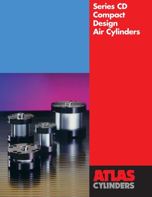
<strong>Series</strong> <strong>CD</strong><strong><strong>Co</strong>mpact</strong><strong>Design</strong><strong>Air</strong> <strong>Cylinders</strong>
New from Atlas . . .The <strong>Series</strong> <strong>CD</strong>M<strong><strong>Co</strong>mpact</strong> <strong>Design</strong> <strong>Air</strong> Cylinder – with Switches<strong>Design</strong>ed for Space Saving/<strong>Co</strong>st Saving ApplicationsThe <strong>Series</strong> <strong>CD</strong>/<strong>CD</strong>M air cylinder is designed andbuilt to meet your demands for space saving, lowcost actuators – and to provide you with maximumreliability and cost effectiveness within minimumspace requirements. The <strong>Series</strong> <strong>CD</strong>/<strong>CD</strong>M, togetherwith the proven performer – the <strong>Series</strong> SS stainlesssteel round body air cylinder – gives you the opportunityto save space, reduce costs and get thereliability and premium quality that you expectfrom Atlas cylinder products.<strong>Series</strong> <strong>CD</strong>/<strong>CD</strong>M air cylinders are available fromstrategically located regional stocking warehousesfor quick delivery. For your cylinder requirements, weare the one source you can depend on for totalresponse-ability.New from AtlasFor applications when piston position sensing isrequired, the <strong>Series</strong> <strong>CD</strong>M, compact design <strong>Air</strong>Cylinder is the choice for a low profile, economicalcylinder. Reed and solid state switches, along withthe magnetic piston, provide actuation points betweenor at either end of the cylinder. Adjustment issimple so you can detect the presence of the pistonalong or at the end of the stroke and send the necessarysignals for circuit control.FREE TEST CYLINDER!Atlas <strong>Cylinders</strong> will supply free of charge a prototype “<strong>CD</strong>/<strong>CD</strong>M” cylinder to any qualified Original <strong>Equipment</strong> manufacturerfor testing purposes. <strong>Co</strong>ntact your local Atlasdistributor for details.
Presenting the <strong>Series</strong> <strong>CD</strong>/<strong>CD</strong>MA True <strong><strong>Co</strong>mpact</strong> <strong>Design</strong> <strong>Air</strong> Cylinder . . .The <strong>Co</strong>st Saving Features – “Inside and Out”are Premium Quality . . .Piston Rod SealBuna-N quad seal provides positivesealing to keep pressure in and dirtout for less maintenance andtrouble free performance.Piston RodHigh strength steel, hard chromeplated for reliable smooth performance,long life, and extendedseal wear.Cylinder BodyHard coated heavy wall aluminumalloy. The tube I.D. coating hasextreme hardness, excellentwear, and seizure resistance,low coefficient of friction, and highcorrosion resistance. This providesexcellent wear qualities and quickbreak-a-ways.Rod BearingHigh density iron providesmaximum support for longer wear.Heads and CapsAnodized aluminum alloy for asolid, lightweight, high strengthperformance. This providesexcellent corrosion resistance,durability, and a long lastingquality appearance.Piston SealBuna-N quad seal provides positivesealing with air.PistonAttached securely to the rod toprovide maximum strength anddurability.The <strong>Series</strong> <strong>CD</strong>/<strong>CD</strong>M Features and Benefits Include:• Low Profile <strong>Design</strong>• 6 Mounting Styles• 8 Bore Sizes from 9 / 16 " to 4"• Temperature Range – -10°F to 200°F(<strong>Series</strong> <strong>CD</strong>M 140°F max.)• Strokes from 1 / 8 " to 6"• Permanent Lubrication• Reduces <strong>Design</strong> Height• Light Weight• Reduces Cylinder Overhang• Specials Available• Maximum Operating Pressure:250 P.S.I. <strong>Air</strong>1
Mounting Style NLipseal/<strong>CD</strong>M Length Adders<strong>Series</strong> <strong>CD</strong>/<strong>CD</strong>M<strong>Air</strong> <strong>Cylinders</strong>MountingStyle NCylinder DimensionsDouble ActingSingle Rod End,Female Rod StyleNo. 9Temperature: -10°F to200°F (optional Fluorocarbonseals). All aircylinders are permanentlylubricated. <strong>Series</strong> <strong>CD</strong>Mmaximum temperature140°F.Bore Boredia. A C D E G J P* Y AA DD EE FB KK LB* MM ZB* dia.9/ 16 .40 1/ 87/ 32 1 1 / 823/ 6423/ 6411/ 3217/ 64 .875 #8-32 #10-32 #4 #8-32 5/ 81/ 43/ 49/ 163/ 4 .44 1/ 81/ 4 1 1 / 223/ 6423/ 643/ 817/ 64 1.219 #10-32 #10-32 #6 #10-32 21 / 325/ 1625/ 323/ 41 1 / 8 .62 1/ 87/ 16 2 1/ 21/ 227/ 643/ 8 1.687 #10-32 1/ 8 #6 5 / 16-24 59 / 641/ 2 1 3 / 64 1 1 / 81 1 / 2 .62 1/ 81/ 2 2 5 / 81/ 21/ 21/ 23/ 8 2.187 1 / 4-28 1/ 8 #10 3 / 8-24 1 5/ 8 1 1 / 8 1 1 / 22 .70 1/ 85/ 8 3 1 / 81/ 21/ 29/ 163/ 8 2.687 1 / 4-28 1/ 8 #10 1 / 2-20 1 1 / 163/ 4 1 3 / 16 22 1 / 2 .70 1/ 85/ 8 3 3 / 45/ 85/ 85/ 87/ 16 3.250 5 / 16-24 1/ 41/ 41/ 2-20 1 1 / 43/ 4 1 3 / 8 2 1 / 23 .75 1/ 83/ 4 4 1 / 443/ 6443/ 6421/ 327/ 16 3.781 5 / 16-24 1/ 41/ 45/ 8-18 1 9 / 327/ 8 1 13 / 32 34 .75 1/ 87/ 8 5 1 / 227/ 3227/ 3249/ 6417/ 32 4.937 3 / 8-24 3/ 85/ 163/ 4-16 1 5 / 8 1 1 3 / 4 4*These dimensions are for the <strong>CD</strong> <strong>Series</strong> with standard piston. See table below for dimensions for the lipseal piston or <strong>CD</strong>M options.Added Length Table for <strong>CD</strong>Mor Lipseal Piston Options<strong>CD</strong>M Option†<strong>CD</strong> with Lipseal Piston Option†BoreMin.Dia. P LB LD XD XJ ZB ZM Stroke P LB LD XD XJ ZB ZM9/16 15/16 1 7 /32 1 11 /32 2 – 1 11 /32 1 19 /32 1/2 5/8 29/32 1 1 /32 1 11 /16 – 1 1 /32 1 9 /323/4 31/32 1 1 /4 1 13 /32 2 1 /32 – 1 3 /8 1 21 /32 1/2 21/32 15/16 1 3 /32 1 23 /32 – 1 1 /16 1 11 /321 1 /8 63/64 1 31 /64 1 3 /4 2 3 /8 1 23 /64 1 39 /64 2 9/16 43/64 1 11 /64 1 7 /16 2 1 /16 1 3 /64 1 19 /64 1 11 /161 1 /2 1 1 /8 1 5 /8 1 59 /64 2 13 /16 1 1 /2 1 3 /4 2 11 /64 7/16 13/16 1 5 /16 1 39 /64 2 1 /2 1 3 /16 1 7 /16 1 55 /642 1 9 / 32 1 25 / 32 2 3 / 32 3 1 / 32 1 21 / 32 1 29 / 32 2 11 / 32 7/ 16 61/ 64 1 29 / 64 1 49 / 64 2 45 / 64 1 21 / 64 1 37 / 64 2 1 / 642 1 / 2 1 21 / 64 1 61 / 64 2 21 / 64 3 21 / 64 1 3 / 4 2 5 / 64 2 37 / 64 1/ 2 1 1 5 / 8 2 3 1 27 / 64 1 3 / 4 2 1 / 43 1 27 / 64 2 3 / 64 2 29 / 64 3 53 / 64 1 53 / 64 2 11 / 64 2 45 / 64 1/ 2 1 3 / 32 1 23 / 32 2 1 / 8 3 1 / 2 1 1 / 2 1 27 / 32 2 3 / 84 1 1 / 2 2 23 / 64 2 49 / 64 4 11 / 64 2 2 31 / 64 3 1 / 64 1/ 2 1 11 / 64 2 1 / 32 2 7 / 16 3 27 / 32 1 43 / 64 2 5 / 32 2 11 / 16†These options not available with the hollow rod option. The <strong>CD</strong>M option also contains the lipseal piston option.Note minimum strokes for <strong>CD</strong>M option.2
<strong>Series</strong> <strong>CD</strong>/<strong>CD</strong>M<strong>Air</strong> <strong>Cylinders</strong>Mounting StylesOptional Rod EndHead BoltClearance HolesMounting Style 4FAvailable Head EndHead TrunnionMounting Style 2FCap TrunnionMounting Style 2RCap BoltClearance HolesMounting Style 4RAvailable Cap EndBore dia. TD TL UT XG XJ*9/ 16 & 3 / 4 Not Available1 1 / 8 .250 1/ 2 3 3/ 851/ 641 1 /2 .250 1/2 3 5 /83/87/82 .250 1/2 4 1 /8 3/8 15/162 1 / 2 .312 5/ 8 5 29/ 64 1 3 / 643 .312 5/ 8 5 1 / 215/ 32 1 1 / 164 .375 3/ 4 7 35/ 64 1 17 / 64*These dimensions are for the <strong>CD</strong> <strong>Series</strong> with standard piston. See tableon opposite page for dimensions for the lipseal piston or <strong>CD</strong>M options.Cap Pivot EyeMounting Style 1Optional MaleRod EndSpecify #4Boredia.A C KK MM9/16 .38 1 /8 #8-32 1/43/4 .50 1 /8 #10-32 5 /161 1 /8 .50 1 /8 5/16-24 1/21 1 /2 .50 1 /8 3/8-24 5/82 .62 1 /8 1/2-20 3/42 1 /2 .62 1 /8 1/2-20 3/43 .75 1 /85/8-18 7/84 .75 1 /83/4-16 1Bore dia. L M CB <strong>CD</strong> FL XD* XE9/16 1/2 1/4 3/8 3/16 21/32 1 13 /32 19/323/4 1/2 1/4 3/8 3/16 21/32 1 7 /16 3/41 1 / 8 1/ 2 1/ 4 3/ 8 3/ 16 49/ 64 1 13 / 16 3/ 41 1 / 2 13/ 16 7/ 16 3/ 4 3/ 8 1 1 / 16 2 3 / 16 1 3 / 82 13/ 16 7/ 16 3/ 4 3/ 8 1 1 / 8 2 5 / 16 1 3 / 82 1 / 213/ 167/ 163/ 43/ 8 1 1 / 4 2 5 / 8 1 3 / 83 1 9 /329/16 1 5/8 1 21 /32 3 1 /16 1 7 /84 1- 9 /32 9/16 1 5/8 1 11 /16 3 7 /16 1 7 /8Order clevis pin from accessories when required.*These dimensions are for the <strong>CD</strong> <strong>Series</strong> with standard piston. See tableon opposite page for dimensions for the lipseal piston or <strong>CD</strong>M options.3
DimensionsSpring Data<strong>CD</strong>M Dimensions<strong>Series</strong> <strong>CD</strong>/<strong>CD</strong>M<strong>Air</strong> <strong>Cylinders</strong>Mounting Style KNor Style KNH (Hollow Rod)Bore dia. B G LD** ZM**9/ 16 * 23/ 643/ 4 13/ 49/ 6423/ 6413/ 16 1 1 / 161 1 / 87/ 321/ 2 1 3 / 16 1 7 / 161 1 /29/321/2 1 19 /64 1 35 /642 3/8 1/2 1 3 /8 1 5 /82 1 / 23/ 85/ 8 1 5 / 8 1 7 / 83 7/ 1643/ 64 1 11 / 16 1 15 / 164 1/ 227/ 32 2 1 / 32 2 9 / 32*Hollow rod not available.**These dimensions are for the <strong>CD</strong> <strong>Series</strong> with standard piston. See table on previous page for dimensions for the lipseal piston or <strong>CD</strong>M options.Spring Return orSpring Extend Data(Available through 2" stroke)Spring Return Dims.Model N<strong>CD</strong>RSpring Extend Dims.Model N<strong>CD</strong>E1/8" to 1" strokeOver 1" to 2" strokeMax.Spring returnMax. SpringSpring extend Spring returnspring rateSpring extendspringXV XW XY XZ force lb/in XV XW XY XZ force9/ 16 1 1 1 / 857/ 64 1 1 / 64 5.7 lb. 4.25 lb./in.3/ 4 1 1 / 64 1 9 / 6459/ 64 1 3 / 64 9 lb. 6 lb./in.1 1 / 8 1 23 / 64 1 31 / 64 1 9 / 32 1 13 / 32 10 lb. 6 lb./in.1 1 / 2 1 25 / 64 1 33 / 64 1 11 / 32 1 15 / 32 13 lb. 5.5 lb./in.2 1 11 /64 1 19 /64 1 13 /32 1 17 /32 13 lb. 5.5 lb./in.2 1 /2 1 3 /8 1 1 /2 1 23 /32 1 27 /32 17.5 lb. 6 lb./in.3 1 1 / 2 1 5 / 8 1 55 / 64 1 63 / 64 24 lb. 6.5 lb./in.4 1 27 / 32 1 31 / 32 2 13 / 64 2 21 / 64 24 lb. 6.5 lb./in.Bore dia.<strong>CD</strong>M Option*†Bore dia.XVAdd thislength to XV,XW, XY, XZ forLipseal PistonSpringratelb/in1 11 /16 1 13 /16 1 37 /64 1 45 /64 5.7 lb. 1.75 lb./in. 9/321 45 / 64 1 53 / 64 1 39 / 64 1 47 / 64 9 lb. 2.5 lb./in. 9/ 321 63 / 64 2 7 / 64 1 29 / 32 2 1 / 32 10 lb. 2.5 lb./in. 1/ 42 1 / 64 2 9 / 64 1 31 / 32 2 3 / 32 12 lb. 2.25 lb./in. 5/ 161 51 / 64 1 59 / 64 2 1 / 32 2 5 / 32 12 lb. 2.25 lb./in. 25/ 642 2 1 /8 2 11 /32 2 15 /64 16 lb. 2.5 lb./in. 3/82 1 /8 2 1 /4 2 31 /64 2 39 /64 23 lb. 2.75 lb./in. 7/162 15 / 32 2 19 / 32 2 53 / 64 2 61 / 64 23 lb. 2.75 lb./in. 13/ 321/8" to 1" stroke Over 1" to 2" strokeSpring return Spring extend Spring return Spring extendXWMin.StrokeXYXZMin.StrokeXV XW XY XZ9/ 16 1 11 / 32 1 23 / 32 5/ 16 1 31 / 64 1 39 / 64 3/ 16 2 9 / 32 2 13 / 32 2 11 / 64 2 19 / 643/ 4 1 39 / 64 1 47 / 64 1/ 8 1 33 / 64 1 41 / 64 3/ 16 2 19 / 64 2 27 / 64 2 13 / 64 2 21 / 641 1 /8 1 59 /64 2 3 /64 1/8 1 27 /32 1 31 /32 1/8 2 35 /64 2 43 /64 2 15 /32 2 19 /321 1 /2 2 1 /64 2 9 /64 1/8 1 31 /32 2 3 /32 1/4 2 41 /64 2 49 /64 2 19 /32 2 23 /322 1 57 / 64 2 1 / 64 1/ 8 2 1 / 8 2 1 / 4 1/ 4 2 33 / 64 2 41 / 64 2 3 / 4 2 7 / 82 1 / 2 2 5 / 64 2 13 / 641/ 8 2 27 / 64 2 35 / 643/ 16 2 45 / 64 2 53 / 64 3 3 / 64 2 15 / 163 2 17 / 64 2 25 / 641/ 8 2 5 / 8 2 3 / 41/ 8 2 57 / 64 3 1 / 64 3 1 / 4 3 3 / 84 2 37 / 64 2 45 / 641/ 8 2 15 / 16 3 1 / 161/ 8 3 13 / 64 3 21 / 64 3 9 / 16 3 11 / 16*These options not available with the hollow rod option. The <strong>CD</strong>M option also contains the lipseal piston option.†Note minimum strokes for <strong>CD</strong>M option.4
How To OrderNon-Standard RodsHow To Order <strong>Series</strong> <strong>CD</strong>/<strong>CD</strong>M <strong>Cylinders</strong>Bore Double Mounting Rod ThreadSize Rod Style <strong>Series</strong> Piston Seals Bumpers Spring Special Style Stroke1.50 K N <strong>CD</strong> L* V B E S 9 x 1.25"Specify:0.56"0.75"1.12"1.50"2.00"2.50"3.00"4.00"Use “K”symbolonly ifdouble rodcylinder isrequired.N = Basic (Std.)or Specify:Single RodStyles; 4F, 4R,2F, 2R, 1orDouble RodStyles; KN,K4R, K2ForHollow RodStyles; KNH,K4RH, K2FHSpecify“<strong>CD</strong>” or“<strong>CD</strong>M”Leave blankfor Standard*Piston Sealor Specify:L = LipsealPiston SealLeave blankfor StandardSeals orSpecify:V = Class 5SealsLeave blankfor cylinderwithoutbumpers orSpecify: “B”= both endsor“H” = headend onlyor“C” = capend only†*Lipseal piston standard on <strong>Series</strong> <strong>CD</strong>M. “L” designator is not required. †Not available on spring extend.Leave blankfor cylinderswithoutspring orSpecify: “E”= SpringExtendor“R” = SpringReturnUse “S”symbol onlyif specialfeature isrequired.<strong>Series</strong> <strong>CD</strong>/<strong>CD</strong>M<strong>Air</strong> <strong>Cylinders</strong>Specify Rod EndThread Style:“9” = StandardFemale Rod Endor“4” = OptionalMale Rod End or“3” = Special RodEnd (specifydimensions orfurnish sketch)Specify ininches.Non-Standard RodsFor non-standard rod ends,please specify rod thread style 3and provide the KK, A, and Cdimensions as needed.Tie Rod TorqueBore (inch pounds)9/16 8 - 103/4 20 - 251 1 /8 20 - 251 1 /2 35 - 402 35 - 402 1 /2 50 - 603 70 - 804 150 - 1605
<strong>Series</strong> <strong>CD</strong>/<strong>CD</strong>M<strong>Air</strong> <strong>Cylinders</strong>Switch MountingSeal KitsTechnical InfoTo sense piston position mount switch along tie rodusing 2 each small set screws.Switch Mounting DataMinimum ActivationPiston Travel Distance fromBore at Midstroke (in.) End of Stroke (in.)Size A (Switch On) (±.01) Head Cap9/16 .32 .20 .13 .133/4 .25 .23 .13 .131 1 / 8 .20 .32 .13 .131 1 / 2 .10 .32 .07 .072 .10 .35 .06 .062 1 / 2 .03 .42 .06 .063 .03 .47 .12 .124 .00 .47 .12 .12Seal Kit Part Numbers for <strong>Series</strong> <strong>CD</strong>/<strong>CD</strong>M <strong>Air</strong> <strong>Cylinders</strong>Single Piston Seal <strong>Design</strong> Seal KitLipseal Piston/Magnetic Piston <strong>Design</strong><strong>Co</strong>nsists of 2 each: Rod Seals, Tube Seals Seal Kit consists of 2 each: Rod Seals, Tie Rodand 1 each: Piston Seal Tube Seals and Piston Seals TorqueBore Rod Part Number Part Number (in./lb.)Size Dia. Class 1* Class 5** Class 1* Class 5**9/ 16" 1/ 4" SKS05<strong>CD</strong>251 SKS05<strong>CD</strong>255 KS05<strong>CD</strong>L251 KS05<strong>CD</strong>L255 8-103/4" 5/16" SKS07<strong>CD</strong>311 SKS07<strong>CD</strong>315 KS07<strong>CD</strong>L311 KS07<strong>CD</strong>L315 20-251 1 /8" 1/2" SKS12<strong>CD</strong>501 SKS12<strong>CD</strong>505 KS12<strong>CD</strong>L501 KS12<strong>CD</strong>L505 20-251 1 / 2" 5/ 8" SKS15<strong>CD</strong>621 SKS15<strong>CD</strong>625 KS15<strong>CD</strong>L621 KS15<strong>CD</strong>L625 35-402" 3/ 4" SKS20<strong>CD</strong>751 SKS20<strong>CD</strong>755 KS20<strong>CD</strong>L751 KS20<strong>CD</strong>L755 35-402 1 / 2" 3/ 4" SKS25<strong>CD</strong>751 SKS25<strong>CD</strong>755 KS25<strong>CD</strong>L751 KS25<strong>CD</strong>L755 50-603" 7/ 8" SKS30<strong>CD</strong>781 SKS30<strong>CD</strong>875 KS30<strong>CD</strong>L871 KS30<strong>CD</strong>L875 70-804" 1" SKS40<strong>CD</strong>101 SKS40<strong>CD</strong>105 KS40<strong>CD</strong>L101 KS40<strong>CD</strong>L105 150-160*Class 1 Seals: Buna-N**Class 5 Seals: FluorocarbonTechnical DataPush/Pull forcesBore Rod Piston PSIdia. area areapush/pull 40 50 60 80 100 125 150 175 200 250Push .248 10 12.5 15 20 25 31 37 43 50 629/ 16.049 Pull .200 8 10 12 16 20 25 30 35 40 50Push .442 17.5 22 26.5 35 44 55 66 77 88 1113/4.076 Pull .366 14.6 18 22 29 37 46 55 64 73 921 1 Push .994 40 50 60 80 99 124 149 174 200 249/8.196 Pull .798 32 40 48 64 80 100 120 140 160 2001 1 Push 1.767 71 88 106 141 177 221 265 309 353 443/ 2.307 Pull 1.460 58 73 88 117 146 182 219 256 292 365Push 3.141 126 157 188 251 314 393 471 550 628 7852.442 Pull 2.699 108 135 162 216 270 337 405 472 540 6752 1 Push 4.908 196 245 294 393 491 613 736 859 982 1227/ 2.442 Pull 4.466 178 223 268 357 447 558 670 781 893 1116Push 7.069 283 353 424 566 707 884 1060 1237 1414 17673.601 Pull 6.486 259 324 389 519 649 811 973 1135 1297 1622Push 12.57 503 628 754 1006 1257 1571 1885 2200 2514 31424.781 Pull 11.78 471 589 707 942 1178 1484 1767 2062 2356 2945Weight chart – basic cylindersN basic Add. per 1/8Bore weight inch of strokedia. in ounces* (ounces)9/ 16 1.1 .083/ 4 2.0 .11 1 / 8 5.0 .21 1 /2 8.5 .42 11.7 .52 1 / 2 18.6 .63 25.1 .74 51.1 1.1* Base weight includes 1 / 8 inch of stroke.6
Switch Data<strong>CD</strong>M DimensionsSwitch SpecificationsPart NumbersBore Reed (Low AMP) NPN Sinking PNP Sourcing9/16" L077030000 L076950000 L0769900003/ 4", 1 1 / 8" L077040000 L076960000 L0770000001 1 / 2", 2" L077050000 L076970000 L0770100002 1 /2", 3", 4" L077060000 L076980000 L077020000<strong>Series</strong> <strong>CD</strong>/<strong>CD</strong>M<strong>Air</strong> <strong>Cylinders</strong>Note: For switches with connectors and cordsets,See <strong>Co</strong>mplementary Products Section.Model Number Reed Switch (Low AMP) NPN PNPSwitching Logic N.O. SPST (Form A) N.O. NPN (Sinking) N.O. PNP (Sourcing)Supply Voltage Range 3 - 125 V AC/DC 6 - 30 VDC 6 - 30 VDCOn-State Voltage Drop 1.7 V Max. 1.2 V max.Current Output Range – 150 mA 150 mABurden Current – 7 mA at 12 V 14 mA at 24 VPower Rating* 5 W (2.5 W) 5 VA (2.5 VA) –Switching Current Range* 5-40 mA (5-20 mA) –Leakage Current 0 1.0 mA 1.0 mALED Function Red (Target Present) Red (Target Present) Green (Target Present)Minimum Currentto Light LED 3 mA 1 mA 1 mAOperating Temperature -10 to 60°C (14 to 140°F) -10 to 60°C (14 to 140°F)Storage Temperature -20 to 60°C (-4 to 140°F) -20 to 70°C (-4 to 158°F)Enclosure ProtectionIEC standard IP 67 NEMA 6PLead Wire 2 conductor, 24 gauge 3 conductor, 24 gaugeLead Wire Length59 inches, 1.5 meter<strong>Co</strong>lor of Cable Gray BlackSwitching Response Max. 300 Hz Max. 1k HzShock Resistance 30 G (300 m/s 2 ) 50 G (490 m/s 2 )Vibration ResistanceDouble Amplitude 1.5 mm (Frequency 10 to 55 Hz 1 scanning, 1 minute)*Number in parentheses pertains to inductive loads.Circuits*Wire colors in parentheses pertain to switches manufactured before 10/15/93.Reed SwitchNPN Sinking OutputPNP Sourcing OutputNOTE: Polarity must be observed forDC operation only.<strong>Co</strong>lor of Cable ............................................... Black“On” State Voltage Drop ................ 1.2V Maximum<strong>Co</strong>lor of Cable ............................................... Black“On” State Voltage Drop ................ 1.2V MaximumBrown (Red*)Black (White*)Blue (Black*)LOAD(+)5 to 30 VDC(—)Brown (Red*)Black (White*)Blue (Black*)LOAD(+)5 to 30VDC(—)Circuit for Switching <strong>Co</strong>ntact Protection (Inductive Loads)(Required for proper operation 24V DC)Put Diode parallel to loads following polarity as shown below.(Recommended for longer life 125 VAC)Put a resistor and capacitor in parallel with the load. Select the resistor and capacitoraccording to the load.D: Diode: select a Diode with the breakdown voltage and current rating accordingto the load.Typical Example—100 Volt, 1 Amp DiodeCR: Relay coil (under 0.5W coil rating)Caution–Use an ampmeter to test reed switch current. Testing devices such as incandescent light bulbs maysubject the reed switch to high in-rush loads.– NOTE: When checking an unpowered reed switch for continuity with a digital ohmmeter the resistancereading will change from infinity to a very large resistance (2 M ohm) when the switch is activated. This isdue to the presence of a diode in the reed switch.– Anti-magnetic shielding is recommended for reed switches exposed to high external RF or magneticfields.– The magnetic field strength of the piston magnet is designed to operate with our switches. Othermanufacturers’ switches or sensors may not operate correctly in conjunction with these magnets.Typical Example:CR: Relay coil (under 2W coil rating)R: Resistor 1 KΩ − 5 KΩ, 1/4 WC: Capacitor 0.1 μF, 600 V– Current capabilities are relative to operational temperatures.– Use relay coils for reed switch contact protection.– The operation of some 120 VAC PLC's (especially some older Allen-Bradley PLC's) can overload thereed switch. The switch may fail to release after the piston magnet has passed. This problem may becorrected by the placement of a 700 to 1K OHM resistor between the switch and the PLC input terminal.<strong>Co</strong>nsult the manufacturer of the PLC for appropriate circuit.– Switches with long wire leads (greater than 15 feet) can cause capacitance build-up and sticking willresult. Attach a resistor in series with the reed switch (the resistor should be installed as close aspossible to the switch). The resistor should be selected such that R (ohms) >E/0.3.7
<strong>Series</strong> <strong>CD</strong>/<strong>CD</strong>M<strong>Air</strong> <strong>Cylinders</strong>Cylinder AccessoriesRod EyeClevis PinAccessoriesBumpersBore Part # A CA CB <strong>CD</strong> CE KK9/16 L073810008 3/815/32 3/8 3/16 1 3 /32 #8-323/4 L073810010 3/815/32 3/8 3/16 1 3 /32 #10-321 1 /8 L073810020 9/1615/32 3/8 3/16 1 9 /32 5/16-241 1 /2 L073810024 5/823/32 3/4 3/8 1 25 /32 3/8-242-2 1 /2 L073810032 11 /1623/32 3/4 3/8 1 27 /32 1/2-203 L073810040 3/4 1 1 5/8 2 3 /8 5/8-184 L073810048 3/4 1 1 5/8 2 3 /8 3/4-16Clevis Bracket(Supplied with Pin)Part # E L M CB <strong>CD</strong> DD FL REL073820012 113/32 7/3225/64 3/16 9/64 9/16 3/4L073820024 1 3 /425/3213/3249/64 3/811/6415/16 1 3 /8L073820040 2 1 /2 1 9/16 1 1 /64 5/817/64 1 1 /4 2Use L073820012 on 9 /16", 3 /4" and 1 1 /8" bore; L073820024 on 1 1 /2,2" and 2 1 /2" bore and L073820040 on 3" and 4" bore.NOTE: The Clevis Bracket is an accessory for the rod eye or thecap pivot eye and cannot be mounted directly to the cylinder.TrunnionBracketPart # SB ST SU SW TD TL TS USL073840016 1/4 7/813/16 5/16 .251 1/2 3/8 1 1 /2L073840020 5/16 115/16 3/8 .313 5/829/64 1 5 /8L073840024 3/8 1 1 /4 1 1 /16 7/16 .376 3/435/64 1 7 /8Use L073840016 on 1 1 /8", 1 1 /2" and 2" bore.Use L073840020 on 2 1 /2" and 3" bore.Use L073840024 on 4" bore.Part # <strong>CD</strong> HP LH <strong>CD</strong>L073830012 3/163/32 129/32L073830024 3/85/32 1 5 /8 1 15 /32L073830040 5/85/32 2 1 27 /32Noise DampeningBumpersBumpers both ends – BBumpers head end – HBumper cap end – C*Bumpers are available at either or both ends of the cylinder to reducenoise for quieter operation. Bumper material is a 70 durometer nitrile.The table shows the distance the stroke is reduced when incorporatingbumpers. This varies with operating pressure as indicated in table.Example: 1.50 N<strong>CD</strong>B 9 x .50" stroke. Bumpers both ends cylinder willhave a working stroke of .43" instead of .50" operating at 80 psi. Forspecial applications call the factory.NOTE: Bumpers shorten actual strokes and are not practical on short strokewith low operating pressure.Bumpers with Cap End or Both Ends will add the “BC” length in chart to “C”dimension.Bumpers on Double End <strong>Cylinders</strong> will add the “BH” length in chart to the “C”dimension (rod extension).Stroke Reduction (in.) Using BumpersBore Bumper Operating PSIdia. location 0 20 40 60 80 100At cap 0.03 0.03 0.02 0.02 0.02 0.020.56 At head 0.07 0.07 0.06 0.05 0.05 0.04Both 0.10 0.09 0.08 0.08 0.07 0.07At cap 0.03 0.02 0.02 0.02 0.01 0.010.75 At head 0.07 0.07 0.05 0.05 0.04 0.04Both 0.10 0.09 0.07 0.06 0.05 0.05At cap 0.05 0.04 0.04 0.02 0.05 0.011.12 At head 0.10 0.08 0.08 0.07 0.07 0.06Both 0.15 0.12 0.11 0.09 0.08 0.07At cap 0.06 0.05 0.04 0.03 0.02 0.021.50 At head 0.10 0.08 0.06 0.06 0.06 0.05Both 0.16 0.13 0.10 0.09 0.07 0.07At cap 0.06 0.05 0.04 0.03 0.02 0.012.00 At head 0.10 0.07 0.06 0.05 0.05 0.04Both 0.16 0.12 0.09 0.08 0.06 0.05At cap 0.06 0.05 0.04 0.02 0.02 0.012.50 At head 0.11 0.07 0.06 0.05 0.05 0.04Both 0.17 0.11 0.10 0.07 0.06 0.05At cap 0.10 0.08 0.06 0.05 0.04 0.033.00 At head 0.14 0.09 0.04 0.07 0.06 0.06Both 0.24 0.16 0.13 0.12 0.10 0.09At cap 0.11 0.10 0.09 0.08 0.07 0.074.00 At head 0.26 0.24 0.23 0.21 0.20 0.18Both 0.37 0.34 0.32 0.29 0.27 0.25*Not available on spring extend.8
Offer of SaleThe items described in this document are hereby offered for sale at prices to be established by Atlas Cylinder Division, and its authorizeddistributors. This offer and its acceptance by any customer (“Buyer”) shall be governed by all of the following Terms and <strong>Co</strong>nditions.Buyer’s order for any item described in its document, when communicated to Atlas Cylinder Division, or an authorized distributor(“Seller”) verbally or in writing, shall constitute acceptance of this offer.1. Terms and <strong>Co</strong>nditions of Sale: All descriptions, quotations,proposals, offers, acknowledgments, acceptances and sales of Seller’sproducts are subject to and shall be governed exclusively by the termsand conditions stated herein. Buyer’s acceptance of any offer to sell islimited to these terms and conditions. Any terms or conditions inaddition to, or inconsistent with those stated herein, proposed by Buyerin any acceptance of an offer by Seller, are hereby objected to. Nosuch additional, different or inconsistent terms and conditions shallbecome part of the contract between Buyer and Seller unlessexpressly accepted in writing by Seller. Seller’s acceptance of any offerto purchase by Buyer is expressly conditional upon Buyer’s assent toall the terms and conditions stated herein, including any terms inaddition to, or inconsistent with those contained in Buyer’s offer.Acceptance of Seller’s products shall in all events constitute suchassent.2. Payment: Payment shall be made by Buyer net 30 days from thedate of delivery of the items purchased hereunder. Amounts not timelypaid shall bear interest at the maximum rate permitted by law for eachmonth or portion thereof that Buyer is late in making payment. Anyclaims by Buyer for omissions or shortages in a shipment shall bewaived unless Seller receives notice thereof within 30 days afterBuyer’s receipt of the shipment.3. Delivery: Unless otherwise provided on the face hereof, deliveryshall be made F. O. B. Seller’s plant. Regardless of the method ofdelivery, however, risk of loss shall pass to Buyer upon Seller’s deliveryto a carrier. Any delivery dates shown are approximate only and Sellershall have no liability for any delays in delivery.4. Warranty: Seller warrants that the items sold hereunder shall befree from defects in material or workmanship for a period of 18 monthsfrom date of shipment to Buyer. THIS WARRANTY COMPRISES THESOLE AND ENTIRE WARRANTY PERTAINING TO ITEMS PRO-VIDED HEREUNDER. SELLER MAKES NO OTHER WARRANTY,GUARANTEE, OR REPRESENTATION OF ANY KIND WHATSO-EVER. ALL OTHER WARRANTIES, INCLUDING BUT NOT LIMITEDTO, MERCHANTABILITY AND FITNESS FOR PURPOSE, WHETHEREXPRESS, IMPLIED, OR ARISING BY OPERATION OF LAW,TRADE USAGE, OR COURSE OF DEALING ARE HEREBYDISCLAIMED.NOTWITHSTANDING THE FOREGOING, THERE ARE NO WARRAN-TIES WHATSOEVER ON ITEMS BUILT OR ACQUIRED WHOLLY ORPARTIALLY, TO BUYER’S DESIGNS OR SPECIFICATIONS.5. Limitation of Remedy: SELLER’S LIABILITY ARISING FROMOR IN ANY WAY CONNECTED WITH THE ITEMS SOLD OR THISCONTRACT SHALL BE LIMITED EXCLUSIVELY TO REPAIR ORREPLACEMENT OF THE ITEMS SOLD OR REFUND OF THEPURCHASE PRICE PAID BY BUYER, AT SELLER’S SOLE OPTION.IN NO EVENT SHALL SELLER BE LIABLE FOR ANY INCIDENTAL,CONSEQUENTIAL OR SPECIAL DAMAGES OF ANY KIND ORNATURE WHATSOEVER, INCLUDING BUT NOT LIMITED TO LOSTPROFITS ARISING FROM OR IN ANY WAY CONNECTED WITHTHIS AGREEMENT OR ITEMS SOLD HEREUNDER, WHETHERALLEGED TO ARISE FROM BREACH OF CONTRACT, EXPRESSOR IMPLIED WARRANTY, OR IN TORT, INCLUDING WITHOUTLIMITATION, NEGLIGENCE, FAILURE TO WARN OR STRICTLIABILITY.6. Changes, Reschedules and Cancellations: Buyer may requestto modify the designs or specifications for the items sold hereunder aswell as the quantities and delivery dates thereof, or may request tocancel all or part of this order, however, no such requested modificationor cancellation shall become part of the contract between Buyerand Seller unless accepted by Seller in a written amendment to thisAgreement. Acceptance of any such requested modification orcancellation shall be at Seller’s discretion, and shall be upon suchterms and conditions as Seller may require.7. Special Tooling: A tooling charge may be imposed for anyspecial tooling, including without limitation, dies, fixtures, molds andpatterns, acquired to manufacture items sold pursuant to this contract.Such special tooling shall be and remain Seller’s property notwithstandingpayment of any charges therefor by Buyer. In no event willBuyer acquire any interest in apparatus belonging to Seller which isutilized in the manufacture of the items sold hereunder, even if suchapparatus has been specially converted or adapted for such manufactureand notwithstanding any charges paid by Buyer therefor. Unlessotherwise agreed, Seller shall have the right to alter, discard orotherwise dispose of any special tooling or other property in its solediscretion at any time.8. Buyer’s Property: Any designs, tools, patterns, materials,drawings, confidential information or equipment furnished by Buyer orany other items which become Buyer’s property, may be consideredobsolete and may be destroyed by Seller after two (2) consecutive yearshave elapsed without Buyer placing an order for the items which aremanufactured using such property. Seller shall not be responsible forany loss or damage to such property while it is in Seller’s possession orcontrol.9. Taxes: Unless otherwise indicated on the face hereof, all pricesand charges are exclusive of excise, sales, use, property, occupationalor like taxes which may be imposed by any taxing authority upon themanufacture, sale or delivery of the items sold hereunder. If any suchtaxes must be paid by Seller or if Seller is liable for the collection of suchtax, the amount thereof shall be in addition to the amounts for the itemssold. Buyer agrees to pay all such taxes or to reimburse Seller thereforeupon receipt of its invoice. If Buyer claims exemption from any sales, useor other tax imposed by any taxing authority, Buyer shall save Sellerharmless from and against any such tax, together with any interest orpenalties thereon which may be assessed if the items are held to betaxable.10. Indemnity For Infringement of Intellectual Property Rights:Seller shall have no liability for infringement of any patents, trademarks,copyrights, trade dress, trade secrets or similar rights except as providedin this Part 10. Seller will defend and indemnify Buyer against allegationsof infringement of U.S. patents, U.S. trademarks, copyrights, trade dressand trade secrets (hereinafter “Intellectual Property Rights”). Seller willdefend at its expense and will pay the cost of any settlement ordamages awarded in an action brought against Buyer based on anallegation that an item sold pursuant to this contract infringes theIntellectual Property Rights of a third party. Seller’s obligation to defendand indemnify Buyer is contingent on Buyer notifying Seller within ten(10) days after Buyer becomes aware of such allegations of infringement,and Seller having sole control over the defense of any allegationsor actions including all negotiations for settlement or compromise. If anitem sold hereunder is subject to a claim that it infringes the IntellectualProperty Rights of a third party, Seller may, at its sole expense andoption, procure for Buyer the right to continue using said item, replace ormodify said item so as to make it non-infringing, or offer to accept returnof said item and return the purchase price less a reasonable allowancefor depreciation. Notwithstanding the foregoing, Seller shall have noliability for claims of infringement based on information provided byBuyer, or directed to items delivered hereunder for which the designsare specified in whole or part by Buyer, or infringements resulting fromthe modification, combination or use in a system of any item soldhereunder. The foregoing provisions of this Part 10 shall constituteSeller’s sole and exclusive liability and Buyer’s sole and exclusiveremedy for infringement of Intellectual Property Rights.If claim is based on information provided by Buyer or if the design for anitem delivered hereunder is specified in whole or in part by Buyer, Buyershall defend and indemnify Seller for all costs, expenses or judgmentsresulting from any claim that such item infringes any patent, trademark,copyright, trade dress, trade secret or any similar right.11. Force Majeure: Seller does not assume the risk of and shall notbe liable for delay or failure to perform any of Seller’s obligations byreason of circumstances beyond the reasonable control of Seller(hereinafter ‘Events of Force Majeure’). Events of Force Majeure shallinclude without limitation, accidents, act of God, strikes or labordisputes, acts, laws, rules or regulations of any government or governmentagency, fires, floods, delays or failures in delivery of carriers orsuppliers, shortages of materials and any other cause beyond Seller’scontrol.12. Entire Agreement/Governing Law: The terms and conditions setforth herein, together with any amendments, modifications and anydifferent terms or conditions expressly accepted by Seller in writing,shall constitute the entire Agreement concerning the items sold, andthere are no oral or other representations or agreements which pertainthereto. This Agreement shall be governed in all respects by the law ofthe State of Ohio. No actions arising out of the sale of the items soldhereunder or this Agreement may be brought by either party more thantwo (2) years after the cause of the action accrues.
A DiverseRangeof ProductsWhatever the industry orapplication, the AtlasAdvantage works for you.Atlas’ diverse line of bothpneumatic and hydrauliccylinders is supported witha worldwide sales andservice network.No other manufactureroffers as diverse a productline base as Atlas. FromJIC tie-rod, to weldedcylinders, to customrequirements, Atlas<strong>Cylinders</strong> will meet yourdemands with qualityand precision.Light Duty Hydraulic <strong>Cylinders</strong> (Tie-Rod)<strong>Series</strong> “L” 1,000 PSI hydraulic service.JIC/NFPA interchangeable.Heavy Duty Hydraulic <strong>Cylinders</strong> (Tie-Rod)<strong>Series</strong> “H” 3,000 PSI hydraulic service.JIC/NFPA interchangeable.Feedback <strong>Cylinders</strong><strong>Series</strong> “ESP” Electronic stroke position, heavy dutyhydraulic cylinder. 3,000 PSI hydraulic service.<strong>Series</strong> “HE” Interchangeable with NFPA tie-rodhydraulic cylinders. Remote electronics available. 3,000PSI.Heavy Duty <strong>Air</strong> <strong>Cylinders</strong><strong>Series</strong> “A” 250 PSI air service.JIC/NFPA interchangeable.<strong>Series</strong> “MM” Mill and mine style construction.250 PSI air service.Light Duty <strong>Air</strong> <strong>Cylinders</strong><strong>Series</strong> “2LA” Aluminum construction.150 PSI air service. NFPA interchangeable.<strong>Series</strong> “SS” and “SSM” Small bore, stainless steelround cylinders. 250 PSI air service.<strong>Series</strong> “<strong>CD</strong>” <strong><strong>Co</strong>mpact</strong> design.<strong>Series</strong> “VA” Valve actuator construction.150 PSI air service.Metric <strong>Cylinders</strong><strong>Series</strong> “AHM” and “APM” Hard metric hydraulicand pneumatic cylinders designed to meet the requirementsof ISO 6020/2 and ISO 6431 respectively.AccumulatorsPiston and bladder-type accumulators. Up to 5,000 PSIhydraulic service.Custom <strong>Cylinders</strong>Up to 48” bore and 40’ stroke. Pressures to 10,000 PSI.<strong>Design</strong>s can include special materials, special construction,and cylinders built to various agency approvals(ABS, DNV, <strong>Co</strong>ast Guard, etc.)29289 <strong>Air</strong>port RoadEugene, OR 97402(541) 689-9111Fax (541) 688-6771www.atlascylinders.com1021 Brooks Street, SEDecatur, AL 35602(256) 355-1812Fax (256) 355-9296