CD Series Compact Design Air Cylinders - Norman Equipment Co.
CD Series Compact Design Air Cylinders - Norman Equipment Co.
CD Series Compact Design Air Cylinders - Norman Equipment Co.

Create successful ePaper yourself
Turn your PDF publications into a flip-book with our unique Google optimized e-Paper software.
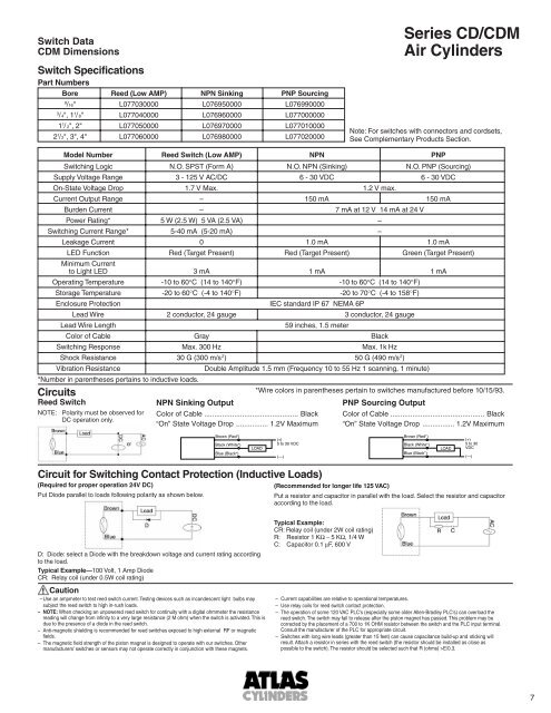
Switch Data<strong>CD</strong>M DimensionsSwitch SpecificationsPart NumbersBore Reed (Low AMP) NPN Sinking PNP Sourcing9/16" L077030000 L076950000 L0769900003/ 4", 1 1 / 8" L077040000 L076960000 L0770000001 1 / 2", 2" L077050000 L076970000 L0770100002 1 /2", 3", 4" L077060000 L076980000 L077020000<strong>Series</strong> <strong>CD</strong>/<strong>CD</strong>M<strong>Air</strong> <strong>Cylinders</strong>Note: For switches with connectors and cordsets,See <strong>Co</strong>mplementary Products Section.Model Number Reed Switch (Low AMP) NPN PNPSwitching Logic N.O. SPST (Form A) N.O. NPN (Sinking) N.O. PNP (Sourcing)Supply Voltage Range 3 - 125 V AC/DC 6 - 30 VDC 6 - 30 VDCOn-State Voltage Drop 1.7 V Max. 1.2 V max.Current Output Range – 150 mA 150 mABurden Current – 7 mA at 12 V 14 mA at 24 VPower Rating* 5 W (2.5 W) 5 VA (2.5 VA) –Switching Current Range* 5-40 mA (5-20 mA) –Leakage Current 0 1.0 mA 1.0 mALED Function Red (Target Present) Red (Target Present) Green (Target Present)Minimum Currentto Light LED 3 mA 1 mA 1 mAOperating Temperature -10 to 60°C (14 to 140°F) -10 to 60°C (14 to 140°F)Storage Temperature -20 to 60°C (-4 to 140°F) -20 to 70°C (-4 to 158°F)Enclosure ProtectionIEC standard IP 67 NEMA 6PLead Wire 2 conductor, 24 gauge 3 conductor, 24 gaugeLead Wire Length59 inches, 1.5 meter<strong>Co</strong>lor of Cable Gray BlackSwitching Response Max. 300 Hz Max. 1k HzShock Resistance 30 G (300 m/s 2 ) 50 G (490 m/s 2 )Vibration ResistanceDouble Amplitude 1.5 mm (Frequency 10 to 55 Hz 1 scanning, 1 minute)*Number in parentheses pertains to inductive loads.Circuits*Wire colors in parentheses pertain to switches manufactured before 10/15/93.Reed SwitchNPN Sinking OutputPNP Sourcing OutputNOTE: Polarity must be observed forDC operation only.<strong>Co</strong>lor of Cable ............................................... Black“On” State Voltage Drop ................ 1.2V Maximum<strong>Co</strong>lor of Cable ............................................... Black“On” State Voltage Drop ................ 1.2V MaximumBrown (Red*)Black (White*)Blue (Black*)LOAD(+)5 to 30 VDC(—)Brown (Red*)Black (White*)Blue (Black*)LOAD(+)5 to 30VDC(—)Circuit for Switching <strong>Co</strong>ntact Protection (Inductive Loads)(Required for proper operation 24V DC)Put Diode parallel to loads following polarity as shown below.(Recommended for longer life 125 VAC)Put a resistor and capacitor in parallel with the load. Select the resistor and capacitoraccording to the load.D: Diode: select a Diode with the breakdown voltage and current rating accordingto the load.Typical Example—100 Volt, 1 Amp DiodeCR: Relay coil (under 0.5W coil rating)Caution–Use an ampmeter to test reed switch current. Testing devices such as incandescent light bulbs maysubject the reed switch to high in-rush loads.– NOTE: When checking an unpowered reed switch for continuity with a digital ohmmeter the resistancereading will change from infinity to a very large resistance (2 M ohm) when the switch is activated. This isdue to the presence of a diode in the reed switch.– Anti-magnetic shielding is recommended for reed switches exposed to high external RF or magneticfields.– The magnetic field strength of the piston magnet is designed to operate with our switches. Othermanufacturers’ switches or sensors may not operate correctly in conjunction with these magnets.Typical Example:CR: Relay coil (under 2W coil rating)R: Resistor 1 KΩ − 5 KΩ, 1/4 WC: Capacitor 0.1 μF, 600 V– Current capabilities are relative to operational temperatures.– Use relay coils for reed switch contact protection.– The operation of some 120 VAC PLC's (especially some older Allen-Bradley PLC's) can overload thereed switch. The switch may fail to release after the piston magnet has passed. This problem may becorrected by the placement of a 700 to 1K OHM resistor between the switch and the PLC input terminal.<strong>Co</strong>nsult the manufacturer of the PLC for appropriate circuit.– Switches with long wire leads (greater than 15 feet) can cause capacitance build-up and sticking willresult. Attach a resistor in series with the reed switch (the resistor should be installed as close aspossible to the switch). The resistor should be selected such that R (ohms) >E/0.3.7