1 IN-SITU REMOVAL OF ARSENIC FROM GROUNDWATER USING ...
1 IN-SITU REMOVAL OF ARSENIC FROM GROUNDWATER USING ...
1 IN-SITU REMOVAL OF ARSENIC FROM GROUNDWATER USING ...
- No tags were found...

You also want an ePaper? Increase the reach of your titles
YUMPU automatically turns print PDFs into web optimized ePapers that Google loves.
<strong>IN</strong>-<strong>SITU</strong> <strong>REMOVAL</strong> <strong>OF</strong> <strong>ARSENIC</strong> <strong>FROM</strong> <strong>GROUNDWATER</strong> US<strong>IN</strong>G PERMEABLE REACTIVEBARRIERS WITH IRON BASED SORBENTSAntónio Fiúza (1), Aurora Futuro (1), Aurora Silva (2), Adelaide Ferreira (3), FernandaGuimarães (3)(1) CIGAR, University of Porto, Faculty of Engineering, Rua Dr. Roberto Frias, S/N, 4200-072 Porto, Portugal,(2) Instituto Superior de Engenharia do Instituto Politécnico do Porto, Rua AntonioBernardino de Almeida no. 431,4200-072 Porto, Portugal(3) LNEG, National Laboratory for Geology and Energy, Rua da Amieira, Apartado 1089,4466-956 S. Mamede de InfestaAbstractFour types of materials have been used in the construction of permeable reactive barriers(PRB) used in the treatment of arsenic contaminated groundwater: zero valent iron (ZVI),furnace slag, sorbents and composite materials (organic + ZVI or a sorbent). Although barriersusing sorbents are promising they are the less studied and no real applications, to ourknowledge, have been implemented to the present. There are no published systematic studiesregarding the potentialities of some iron oxides and hydroxides that are available in the marketfor a long time, such as ARM 300 and GEH 102.This research analyzes the capacities and drawbacks of these last two sorbents as materials forin-situ removal of arsenic using laboratory studies at batch scale and continuous operation incolumns. Isotherms and breakthrough curves were determined for different operating conditionsthat are compared. Both sorbents adsorb As(III), As(V) and mixtures of both. Breakthroughcurves allow determining the uptake capacity of both sorbents that are similar, 20 g As/ kg, aconsistent value somehow inferior to values already published in the literature.Finally it is studied the spatial distribution of arsenic concentration in the sorbent particles usingan electron probe microanalyzer (EPMA) to produce backscattered electron images (BSE) andelemental mapping through wavelength-dispersive spectroscopy (WDS). Results show thatsorbent particles adsorb arsenic through chemisorptions: arsenic enrichment coincides withdepletion in oxygen and iron. Spatial mapping of the concentrations allows infer that theremoval mechanisms are different: while for ARM 300 reductive precipitation is relevant for GEH102 the adsorption mechanisms with complex formation are prevalent.Keywords: iron based sorbents, in-situ arsenic removal, permeable reactive barriers,breakthrough curves.11. IntroductionAnomaly arsenic concentrations in groundwater are generally of natural origin and caused bynatural dissolution of minerals. Arsenic is always present in natural waters either in the reducedform As(III) or in the oxidized form As(V). Toxicity depends upon the chemical specie and, ingeneral, As(III) is 25 to 60 times more toxic than As(V). Arsenic concentrations in cleansuperficial waters and in groundwater are normally in the range 1 – 10 g/L. Very highconcentrations in As (> 1000 g/L) have been found in different areas like Taiwan, West Bengal,India, Bangladesh, Mexico and some areas in Argentina, Chile and the United States. Arsenic isalso a problem in many countries of the European Community. For instance in the GreatHungarian Plane and some areas in Romania concentrations between 150 and 180g/L arefound. In Portugal and Spain it is possible to find concentrations of As in former mining areasranging from 100 to 2000 ppb.Conventional technologies for the treatment of groundwater like pump and treat have importantdisadvantages: very high costs, especially if the treatment is long, and a general reducedefficiency. For this reason the in-situ technologies have received greater attention in the lastyears. Some alternatives are available like bioremediation, permeable reactive barriers, in-situchemical treatment, enhanced natural attenuation and electro-kinetics. Permeable reactivebarriers is the in-situ technology that has received more attention and some applications werebuilt in several countries.
2. Permeable Reactive Barriers for Arsenic Removal – State of artSeveral materials have been tested and used for the in-situ treatment of arsenic contaminatedgroundwater. We briefly refer those with more application: a) zero valent iron (ZVI); (b) furnaceslag produced in iron works; c) sorbent materials such as iron hydroxides and activated aluminaand d) multifunctional barriers, either multiple or composite, constituted by a first barrier withcompost or other organic material that promotes the microbial reduction of sulphates followedby a second layer (or barrier) constituted by ZVI or other sorbent.In the barriers that use granular ZVI Fe is oxidized and FeOOH is produced at the surface of thegrains; this compound has capacity to adsorb metals and metalloids such as arsenic (Nikolaidis,2003). ZVI is a very efficient reducing agent that can remove both inorganic and organicarsenic. The kinetics is very fast; for instance McRae (1999) observed the removal of As(V)from concentrations of 1000 to
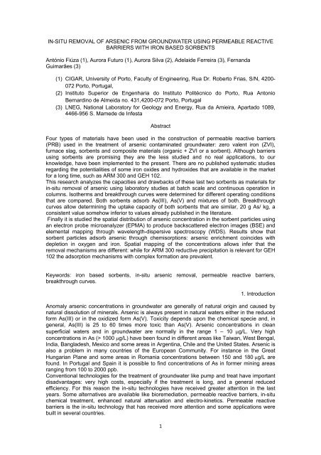
As in Solid Phase (mg/g)1614121086420Isotherms0 1 2 3 4 5As in Liquid Phase (ppm)As IIIAs VFigure 1 – Sorption isotherms for As(III) and As(V) using ARM 300The isotherms suggest that As(V) is more adsorbed to ARM 300 than As(III). Similar resultswere obtained for GEH 102.The continuous tests through a fixed bed sorption column filled with the reactive medium mixedwith quartz sand, were programmed in order to quantify the influence of the interstitial watervelocity through the pores. Three different flowrates were used – 5, 10 and 20 mL/mincorresponding respectively to interstitial velocities of 1.698x10 -4 , 3.395x10 -4 and 5.09x10 -4 m/s.The last value was the highest that could be safely used taking into account the size and thecharacteristics of the column. The cumulative effluent volume was periodically measured andsamples were collected for immediate measurement of pH and conductivity. HCl was thenadded for preservation until the chemical analysis was performed.The general conclusions could be drawn from these experiments:‐ The pH, starting from neutral water, decreases slightly with time;− The conductivity decreases from 250 to 186 S cm -1 .‐ Hydrogen ions are generated as a consequence of the As sorption by the ARM 300;this proves that the sorption is not only of physical origin but there are alsosimultaneously chemical reactions involved.Figures 2 and 3 represent the values for the arsenic concentrations in the effluent normalized bythe average initial concentration at the inlet for interstitial velocities for the As(III) and for thevelocity of 3.395.10 -4 m/s for the As(V).4
C/C 0 ‐ As (III)10,90,80,70,60,50,40,30,20,100 5 10 15 20Time [days]1,698x10‐43,395x10‐45,09x10‐4Figure 2 – Time evolution of As(III) concentrations using different interstitial velocities[As (III)] ppb100090080070060050040030020010000 2 4 6 8 10Time [days]Figure 3 –Time evolution of As(V) concentrations using an interstitial velocity of 3.395.10 -4 m/sThe average concentration at the inlet (C 0 ) and the experimental breakthrough timecorresponding to 50% of the column saturation (t 50% ) are shown in Table 1 for all the tests. Anincrease in the interstitial velocity corresponds to a decrease in the t 50% . This expectedbehaviour corresponds to a decrease in the residence time. This relationship is not linear.Table 1 – Experimental data for the breakthrough time t 50%ArsenicFlowrate(mL/min) C 0 (g/L) t 50% (h)5 1077 58Arsenic (III) 10 1024 4620 1109 65 984 35Arsenic (V) 10 1046 520 1048 45
For the flowrate of 20 mL/min the residence time is much lower than for the other flowrates andleads to a much faster saturation of the column. Comparing both As species for the flowrates of5 and 10 mL/min it is noticeable that t 50% is higher for As(III), in accordance with the isothermspreviously obtained.The same tests were performed for the same flowrates using a solution with a mixture of As(III)and As(V) in the same proportion. Figure 4 represents C(t)/C 0 as a function of the cumulativeeffluent volume. It is also noticeable that the lowest flowrate allowed a higher proximity to thesaturation than the other flowrates tested.C(t)/C010,90,80,70,60,50,40,30,20,10Comparison of different flowrates0 50 100 150 200Cumulative Effluent Volume (L)5 mL/min 10 mL/min 20 mL/minFigure 4 – Total arsenic breakthrough curves for different flowratesThe uptake capacities for the flowrates of 5 and 10 mL/min are similar with a value of 20 gAs/kg of sorbent.5. Comparison tests between the sorbentsComparison tests between ARM 300 and GEH 102 were performed using two columns fed inparallel by the same arsenic solution (around 1000 g/L) using a multi-channel peristaltic pump.Tests were also performed for each sorbent using the same operating conditions: same amountof sorbent and sand, same concentration in arsenic of the feed solution and same flowrate.These last results are here analyzed.In both tests 1.5 g of sorbente was used. The sorbents were mixed with pure quartz sand (ironfree) and inserted in the column. In the test for the GEH 102, the arsenic feed solution had aconcentration of 1136 g L -1 and the average flowrate was 0,115 L h -1 , which corresponds to aninterstitial velocity of 1.10 -4 m/s. The flow was ascending and the effluent was collected from thetop and periodically sampled. The effluent cumulative volumes were also measured at the sametime.In the test for ARM 300 the feed solution had a concentration of 1002 g L -1 and was fed to thecolumn at an average flowrate of 0,127 L h -1 which corresponds to an interstitial velocity of1.1*10 -4 m/s. The procedures for collecting samples and measuring the cumulative effluentvolumes were similar.The cumulative effluent concentrations for both sorbents are shown in figure 56
As Concentration (ppb)80070060050040030020010000 5 10 15 20 25 30Cumulative Effluent Volume (L)Figure 5 – Comparison between ARM 300 and GEH 102GEH 102ARM 300The most relevant conclusions are the following:‐ The residence time was too short in relation to the kinetics demand. For these reasonnot all the As had contact time sufficient to be adsorbed;‐ This result was not expected because the water velocity recommended for operationwith ARM 300 in water treatment columns is 1.3.10 -3 m/s and the velocity used wasinferior;‐ In both cases the saturation of the uptake capacity was not reached and the volume ofwater that passed through the column was insufficient;‐ GEH 102 demonstrates a slightly better performance;‐ An extrapolation method was developed to estimate the uptake capacities of bothsorbents and the following results were obtained: 20,6 g of As/kg sorbent for GEH 102and 20,8 for ARM 300. In a previous study Ipsen (2005) found an uptake capacity of 36g As/kg for the GEH sorbent.‐ In a potential field application it would be required to build two permeable reactivecolumns, with a reasonable distance between them, so that the second barrier wouldallow attain environmentally acceptable arsenic concentrations.‐ Alternatively, an excess of at least 100% of the sorbent in relation to the necessitiesestimated by the uptake capacity would be required.6. Possible removal mechanismsSeveral removal mechanisms are possible, such as reductive precipitation of As, adsorption tothe iron hydroxides and still mineral formation (Farrell, 2001). The reductive precipitation occursaccording to2 0HAsO 7H 5e As 4HO E 0.499mV4 2 H This reaction is very probable with ZVI. Another possibility is adsorption that may occuraccording with the following reactions (Farrell, 2001) FeOH HAsO22124 H FeHAsO4 H2OK = 102226.24 2H Fe2HAsO4 2 2OK = 102( FeOH) HAsOHIn fact both species, As +3 and +5, are removed by mono and bi-dentate complex formationwith ferric hydroxides.Still, another possibility for GEH 102 is the arsenic precipitation according to (Farrell, 2001) Fe( OH) 3 H2AsO4 H FeAsO42H2O H2O7
6. Study of the sorption mechanisms using an Electron Microprobe AnalyserIn order to enlighten the mechanisms of sorption, samples of the sorbent were collected aftertheir usage in fixed bed columns tests and were analysed using an Electron MicroprobeAnalyser. The samples were impregnated in resin and polished with diamond paste forexamination and analysis by a Field Emission Electron Microprobe (EPMA), model Jeol JXA-8500F. Afterwards, they were coated with carbon to ensure electrical conductivity at thesurface. Electron backscattered images were obtained from the sorbent particles. Quantitativeanalysis at selected points and all WDS X-ray intensity dot maps were obtained with thefollowing operating conditions: 15kV, 60nA and 1µm beam diameter. A dwell time of 10ms wasused for X-Ray dot maps.6.1. Sorbent ARM 300Figure 6 shows a mapping of arsenic, nickel, oxygen and iron concentrations in a particle ofARM 300 after being submitted to arsenic removal.Figure 6 – Mapping of concentration of different elements in a Particle of ARM 300The observation of the largest particle allows several conclusions:‐ The deposition of arsenic was predominantly done at the lower face of the particle,showing that is a superficial reaction; arsenic was not captured at the higher faceprobably due to the fact that this particle was in contact with another particle of sorbentor sand. Although the sorbent particle has several fractures arsenic has not penetratedto the inner part of the particle through those factures. It can be concluded that it isrequired for the occurrence of the reaction the existence of an exposed surface incontact with the solution;‐ There is a depletion of oxygen concentrations at the surface of the particleindependently from the fact whether arsenic was removed or not from that particularsurface;‐ The same effect happens with iron, although the thickness of the depletion layer isthinner;8
‐ Nickel concentrations are relatively uniform within the particle.‐ Due to these changes the sorption is undoubtedly of chemical origin (chemisorption)and thus irreversible.It should also be noticed as a remarkable fact then existence of a small particle intenselycharged in arsenic distributed through all the volume of the particle, at the upper right corner;also a fraction of another particle in the same conditions is seen in the same area. It remainsquestionable if part of the external adsorbed arsenic layer can be detached from the surfaceAnother particle was selected for chemical analysis as shown in Figure 7.Figure 7 – Points selected for chemical analysis in an ARM 300 particlePoints 11, 12 and 13 were selected for chemical analysis for the following elements Si, Cl,As, Mg, Fe, Cr, S, Al, Mn, Ni, Ti, Zn and Ca. Table 2 shows the results obtained.Concentrations for all the elements are expressed as oxide.Table 2 – Spatial distribution of concentrations in a particle of ARM 300 (percentage)Element 11 12 13AverageconcentrationStandarddeviationSiO 2 1.3759 1.1374 0.6826 1.065 0.352Cl 0.6966 0.6976 0.6902 0.695 0.004As 2 O 5 2.82 3.07 3.59 3.160 0.393MgO 0.0974 0.0964 0.0505 0.081 0.027FeO 64.51 64.91 54.84 61.420 5.702Cr 2 O 3 0.005 0.0076 0.0541 0.022 0.028SO 3 0.6799 0.7282 1.1243 0.844 0.244Al 2 O 3 0.2535 0.0919 0.2078 0.184 0.083MnO 0.2564 0.2846 0.1925 0.245 0.047NiO 0.794 0.7465 0.0507 0.530 0.416TiO 2 0.0747 0.0817 0.0209 0.059 0.033ZnO 0.5027 0.7062 0.0392 0.416 0.342CaO 0.475 0.5304 0.7395 0.582 0.1399
Total 72.5412 73.0886 62.2824The concentration of adsorbed Arsenic is higher at the surface of the sorbent although arsenichas apparently penetrated to the inner part of the particle, even if the particle has a large size(scale is indicated at the picture). Nevertheless, concentrations decrease from the outer to theinner side of the particle. Notice that the highest concentration in As coincides with the lowestconcentration in Fe suggesting that part of the Fe is reduced to a soluble Fe(II) form. Areductive precipitation is possible and probably coexisting with other removal mechanisms.6.2. Sorbent GEH 102Figure 8 shows the mapping of the concentrations for different elements (As, Ni, O and Fe) in aparticle of GEH 102 after it was exposed to arsenic sorption in a fixed bed column during 30days.Figure 8 – Mapping of concentrations in a particle of GEH102The following observations may be noticed:‐ Arsenic is captured around all the external surface of the sorbent particle constituting alayer with variable thickness;‐ The increase in arsenic concentrations coincide with a net depletion in oxygen;‐ Iron concentrations remain approximately constant inside the particle.Figure 9 presents another set of sorbent particles and the mapping of iron concentrations. It isnoticeable a decrease in the concentrations at the outer surface of the particles. Concentrationsin the inner part are approximately homogeneous although small heterogeneities with higherconcentrations can be noticed.10
Figure 9 – Iron concentrations in a set of particlesThe mapping of arsenic concentrations was also performed (Figure 10)Figure 10 – Mapping of As concentrationsSome facts:‐ Arsenic is captured through the exposed surface of the particles. If some particlespresent only a part of the external surface with higher arsenic concentrations it is due tothe fact that the particle was in contact with another (sorbent or sand) and the surfacedidn’t contact the arsenic solution;‐ One of the particles didn´t captured arsenic, probably due to the reasons alreadyexposed;‐ The thickness of the sorption layer may reach values as high as 40 m.One of the particles was selected for quantitative chemical analysis (Figure 11).11
Figure 11 – Selected particle and points that were submitted to chemical analysisFive points, designated from 6 to 10, were submitted to chemical analysis. Points 7 and 10correspond to an external layer that was in contact with the contaminated water; points 6 and 9are inside the particle bur near the external contact layer and point 8 is the core of the particle.Thirteen elements were analysed: Si, Cl, As, Mg, Fe, Cr, S, Al, Mn, Ti, Zn e Ca. Results arepresented in Table 3.Table 3 – Spatial distribution of concentrations in a particle of GEH 102 (Percentage)Element 6 7 8 9 10AverageconcentrationStandarddeviationSiO 2 1.804 0.9861 2.0836 1.5214 0.841 1.447 0.529Cl 0.6641 0.607 0.6755 0.7179 0.69 0.671 0.041As 2 O 5 1.0785 0.9742 - 1.92 2.47 1.611 0.712MgO 0.0279 0.1015 - 0.1326 0.0187 0.070 0.056FeO 64.08 51.01 65.68 67.16 56.78 60.942 6.836Cr 2 O 3 - 0.0351 - 0.0161 - 0.026 0.013SO 3 0.7387 0.4951 1.024 1.0029 0.6738 0.787 0.225Al 2 O 3 0.1067 0.1179 0.0862 0.1914 0.1233 0.125 0.040MnO 0.2855 0.0286 0.1215 0.1568 0.2214 0.163 0.098NiO 1.0415 0.0078 1.0148 0.9871 - 0.763 0.504TiO 2 0.1859 - 0.1353 0.0069 0.0017 0.082 0.093ZnO 0.7099 0.1025 0.3875 0.299 0.0551 0.311 0.262CaO 0.393 0.5452 0.2898 0.3702 0.6351 0.447 0.140Total 71.1157 55.011 71.4983 74.4824 62.5102The following conclusions may be stressed:‐ There is no As in the inner part of the particle;‐ The highest As concentration is found at point 10 and belongs to the external sorptionlayer; point 9 is also included in the same layer;‐ In the sorption layer located in the opposite side of the particle (points 6 and 7)concentrations are relatively homogeneous but lower than in the opposite face.‐ This suggests that chemisorption prevails in relation to the other possible precipitationmechanisms.12
ConclusionsThis research proves that IBS may be used as reactive media in PRB. The two commercialsorbents tested, ARM 300 and GEH 102, remove efficiently both As(III), As(V) and theirmixtures. As(V) is removed easier than As(III). Breakthrough curves obtained in differentoperating conditions allowed comparing both sorbents: the loading capacity is similar, around20 g of As/ kg, and GEH has a slightly more favourable performance. Particles of the sorbents,after subjected to adsorption tests in fixed bed columns during 30 days, were subjected toanalysis using an electron microprobe analyzer. Spatial mapping of the concentrations allowsinfer that the removal mechanisms are different: while for ARM 300 reductive precipitation isrelevant for GEH 102 the adsorption mechanisms with complex formation are prevalent.AcknowledgementsThe authors would like to thank The National Foundation for Science and Technology(Fundacão para a Ciência e Tecnologia FCT) for the financial support of this research that ispart of the project. PTDC/ECM/70216.REFERENCESBaker M.J., Blowes D.W., Ptacek C.J., 1998, Laboratory development of permeable reactivemixtures for the removal of phosphorous from onsite wastewater disposal systems, Environ. Sci.Technol. 32, 2308–2316 .Bang S., Korfiatis G. P., Meng , 2005 , Removal of arsenic from water by zero-valent iron,Journal of Hazardous Materials 121, 61–67.Beak. D. G., Wilkin R.T.,2009, Performance of a zerovalent iron reactive barrier for thetreatment of arsenic in groundwater: Part 2 Geochemical modeling and solid phase studies,Journal of Contaminant Hydrology, 106, 15–28.Cortina J-L., Fiúza A., Silva A., Litter M, 2010, Tecnologías de tratamiento in-situ de aguassubterrâneas, Chapter seven of “Tecnologías Económicas Para El Abatimiento de Arsénico enAguas”, Project Cyted, Edited by Marta I. Litter, Ana María Sancha, Ana María Ingallinella.Driehaus, W., Jekel, M. and Hildebrandt, U., 1998, Granular ferric hydroxide – a new adsorbentfor the removal of arsenic from natural water, Blackwell Science Ltd. J. Water SRT- Aqua 47, 30–35Farrel J., Melitas N., Conklin M., O’Day P., 2001, Understanding Arsenic Removal Mechanismsin Iron Media Filters, International Conference “Arsenic in Drinking Water”, New York.Ferreira M. A., Barros A., A, 2002, Determination of As(III) and arsenic(V) in natural watersby cathodic stripping voltammetry at a hanging mercury drop electrode, Analytica ChimicaActa 459, 151–159.Gibert O, Pablo J, Cortina J-L., Ayora C., 2010, In situ removal of arsenic from groundwater byusing permeable reactive barriers of organic matter/limestone/ zero-valent iron mixtures EnvironGeochem Health, 32:373–378Ipsen S-O., Gerth J., Förstner U., 2005, Identifying and testing materials for arsenic removal bypermeable reactive barriers, Consoil 2005, 1815-1817.13
Köber R., Daus B., Ebert M., Mattush J., Welter E., Dahmke A., 2005, Compost-basedpermeable reactive barriers for the source treatment of arsenic contaminations in aquifers:column studies and solid-phase investigations, Environ. Sci. Technol. 39, 7650-7655.McRae, C.W.T., 1999, Evaluation of reactive materials for in situ treatment of arsenic III, arsenicV and Selenium VI using permeable reactive barriers: laboratory study, MSc Thesis, Universityof Waterloo, Waterloo, Ontario, Canada.Nikolaidis, N.P., Dobbs, G.M., Lackovic, J.A., 2003, Arsenic removal by zerovalent iron: field,laboratory and modeling studies, Water Research 37, 1417–1425.Silva A., Freitas O., Figueiredo S., Vandervliet B., Ferreira A., Fiúza A., 2009, Arsenic RemovalUsing Synthetic Adsorbents: Kinetics, Equilibrium and Column Study, 12th EuCheMSInternational Conference on Chemistry and the Environment.7 June 2009, Stockholm, Sweden.Wilkin R. T., Acree S. D., Beak D. G., Ross R. R., Lee T. R., Paul C. J., 2008, Field applicationof a permeable reactive barrier for treatment of arsenic in ground water”, Office of Research andDevelopment, National Risk Management Research Laboratory, Ada, Oklahoma 74820, EPA .Wilkin R. T., Acree S. D., Ross R. R., Beak D. G., Lee T. R., 2009, Performance of a zerovalentiron reactive barrier for the treatment of arsenic in groundwater: Part 1 - Hydrogeochemicalstudies, Journal of Contaminant Hydrology 106, 1–14.14