Series J Shaft Mounted Gearbox - Benzlers
Series J Shaft Mounted Gearbox - Benzlers
Series J Shaft Mounted Gearbox - Benzlers

Create successful ePaper yourself
Turn your PDF publications into a flip-book with our unique Google optimized e-Paper software.
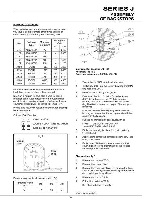
Mounting of backstopSERIES JASSEMBLYOF BACKSTOPSWhen using backstops in shaftmounted speed reducersyou have to consider among other things the limit ofspeed and torque according to the following table.SizeBackstopTypeMax inputtorque NmInput speedr/minMin MaxJ 12 ASNU15EP 75 - 2400J 22 ASNU17EP 112 - 2300J 32 ASNU20EP 160 - 2100J 52 ASNU30EP 500 - 1400J 72 ASNU30EP 750 - 1200J 100 RSCI40 1600 720 7600J 110 RSCI45 1800 665 6600J 125 RSCI50 2800 610 6100J 140 RSCI60 4700 490 6100J 160 RSCI70 6100 480 4500J 190 RSCI80 9000 450 4000Max input torque at the backstop is valid at 4,5 x 10 5load changes and must never be exceeded.Direction of rotation for back stop is valid for doublereduction gears. Look at reducer from input shaft sideand determine direction of rotation of output shaft sleeve,counterclockwise (BV) or clockwise (BH). See Fig 1.Please state required direction of rotation when orderingback stop reducerColumn 15 & 16 entriesOutputshaft- - NO BACKSTOPB V COUNTER CLOCKWISE ROTATIONB H CLOCKWISE ROTATIONPicture shows counter clockwise rotation (BV)Tightening torque(29:3)Fig 1IntputshaftJ12 J22 J32Nm 17 35 41Fig 1Instruction for backstop J12 - 32.Assembly see fig 2Operation temperature -30 °C to +100 °C.I. Take out cover (14*) from standard reducer.2. Fit the key (29:6) into the keyway between shaft (1*)and back stop (29:7).3. Mount the circlip into groove (29:5).4. Determine direction of rotation for the back stop(29:7), fit the back stop unit (29:6) into reducerhousing push it into close contact with the spacerring (Direction of rotation is changed if back stop isreversed).5. Push the backstop bracket (29:2) into the reducerhousing and ensure that the two lugs locate with thegroove on the back stop.6. Rub the mechanical joint discs (29:1) with oil.NOTE: OIL MUST NOT CONTAINwwwMOLYBDENUMDIFULSIDE7. Fit the mechanical joint discs (29:1) into backstopbracket (29:2).8. Apply sealing compound on thread under screw head(29:3) 5 mm width.9. Fit the cover (29:4) with screws enough to adjustcover. Tighten screws alternating until the requiredtightening torque is reached.Dismount see fig 21. Dismount the screws (29:3).2. Dismount the cover (29:4).3. Dismount the mechanical joint unit by using the threescrews (29:3) and tighten the screws against the shaftend / backstop with equal load.4. Dismount the circlip (29:5).5. Pull out the backstop (29:7).Do not clean before assembly.*Acc to spare parts list.65