PRESSURE REGULATORS SERIES 320 - GCE
PRESSURE REGULATORS SERIES 320 - GCE
PRESSURE REGULATORS SERIES 320 - GCE

Create successful ePaper yourself
Turn your PDF publications into a flip-book with our unique Google optimized e-Paper software.
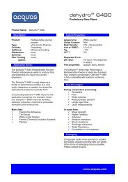
CYLINDER <strong>PRESSURE</strong> <strong>REGULATORS</strong> FMD 322-14/-16/-18Dual-stage,for inert, reactive, flammable and oxidizing gases and mixtures, not suitable for acetylene,purity max. 5.0cylinder pressure 230 bar / 3300 psi,downstream pressure range 0.5 - 10.5 bar / 7 - 150 psioutType -14inSPECIAL FEATURES•Downstream pressure is independent of the upstream pressure due to the dual-stage designDiaphragm valve (FMD 322-16 with 90° shut-off function)Pressure regulator with stainless steel diaphragmATEX conform adjustment knobGauge in safety version accordance with DIN EN 837outType -16inDESCRIPTIONThese pressure regulators consist of cylinder connections, pressure regulator, inlet- and outlet gauges, diaphragmshut-off valve (Type -16) regulating valve (Type -18), relief valve, tube fitting on outlet.outFLOW SCHEMATICBA6542Type -1831in1 Cylinder connection2 Dual-stage pressure regulator3 Upstream pressure gauge4 Downstream pressure gauge5 Relief valve6 Downstream shut-off valve (only type -16)/ downstream regulatingvalve (only type -18)BA Process gas outletPERFORMANCE DATAAPPLICATIONThe FMD 322-14 is the base model. The FMD 322-16 permits shutting-off of the gas flow while maintaining thepressure regulator settings, the regulating valve on the FMD 322-18 enables a fine controling of the gas flow. Thedual-stage pressure regulator ensures the uniformity of the downstream pressure independent of the level of thecylinder pressure.TECHNICAL DATABody:Seat seals:Body seals:Diaphragm:Leakage rate:Stainless steel 316L (1.4404) specially cleaned or Brass CW614 (CuZn39Pb3)specially cleaned1st stage: PCTFE, 2nd stage: PTFEPCTFE (Stainless steel), PVDF (Brass)Stainless steel< 1×10 -9 mbar l/s Helium (outboard)< 1×10 -6 mbar l/s Helium (across the seat)Relief valve seat seals: Stainless steel: FKM, (EPDM, FFKM) *Pressure gauge range:Brass: EPDM, (FKM)-1 to 10 bar (-15 to 145 psi), -1 to 18 bar (-15 to 260 psi),0 - 315 bar (0 - 4500 psi)Weight: approx. 2.1 kg (Type -14), 2.4 kg (Type -16/18)Working temperature: -25 °C to +70 °C / -13 °F to 158 °FPerformance data:see belowBasic design aspects: see page 2Cylinder connection:according to gas type*on requestDIMENSIONSapprox. 112approx. 200approx. 184148approx. 225ORDER CODETypeFMD 322-14FMD 322-14FMD 322-16FMD 322-18MaterialBCBC = brass CrplatedSS = stainlesssteelUpstream pressureFF = 230 bar/3300 psiDownstream pressure66 = 0.5 - 6 bar / 7- 85 psi10 = 1 - 10.5 bar / 15 - 150 psiInletDINDINANSI/ AFNOR/NBN/BS 341/CGA/NEN/UNIOutletCL60=NPT 1/4"fCL6/ CL8**CL 1/8" /CL 1/4"NO6** = Outlet: (CL6 = tube fitting for 6 mm outside diameter, NO6 = hose connector for 6 mm hose inside diameter). Please note the "burst rate chart" when choosing the tube fittings in chapter 5.4Gas typeGASPleasespecifySubject to change without notice
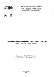
Bearb.Zust. Änderung Datum NameZust. Änderung Datum NameGepr.Bearb.Gepr.LINE <strong>PRESSURE</strong> <strong>REGULATORS</strong> LMD <strong>320</strong>-01/-03/-04/-05outinSingle-stage,for inert, reactive, flammable and oxidizing gases and gas mixtures,purity max. 5.0,inlet pressure LMD <strong>320</strong>: 40 bar / 600 psi,optional 230 bar / 3300 psi,downstream pressure range LMD <strong>320</strong>: 0 - 14 bar / 200 psi,outinLMD <strong>320</strong>-04SPECIAL FEATURESCompact design•Excelent pressure adjustment4 or 6 port configurationLMD <strong>320</strong>-01outinDESCRIPTIONA broad application spectrum through the 4-port configuration (type -01/-04) or 6-Port-configuration (type -03/-05), which can be delivered respectivly, with (type -04/-05) or without (type -01/-03) a relief valve. With type-03and type-05 the use of contact gauge (accessories) in conjunction with alarm box (accessories) facilitates themonitoring of gas reserves.outLMD <strong>320</strong>-03CONNECTIONS (FRONT VIEW)TYPE -01/-04Downstream-outletNPT 1/4"finOutlet pressure gaugeNPT 1/4"f90 °90 °LMD <strong>320</strong>-0590 °90 °High pressure-inletNPT 1/4"fAPPLICATIONThe LMD <strong>320</strong> reduces line pressure to give a lower supply pressure. Through its compact design this regulator isespecially well suited for use in analytical or chemical apparatuses or processes.TECHNICAL DATABody:Seat seals:Body seals:Relief valve seat seals:Performance data:stainless steel 316L (1.4404) specially cleaned or brass CW614 (CuZn39Pb3)specially cleaned, nickel-plated and chrome-platedPCTFEPCTFE, PVDF (Brass)SS: FKM, (EPDM, FFKM)*, Brass: EPDM, (FKM)*see the single stage regulatorPressure gauge range: -1 - 5 bar (-15 - 73 psi) / -1 - 10 bar (-15 - 145 psi),0 - 25 bar (0 - 365 psi),0 - 80 bar (0 - 1150 psi) / 0 - 315 bar (0 - 4500 psi)Weight: approx. 1.1kg (type -01), 1.2kg (type -03)Dimensions (w×h×d):Inlet/Outlet:*on requestapprox. 115×140×120 to 140 mmNPT 1/4"f, optional tube fittingTYPE -03/-05Outlet pressuregaugeNPT 1/4"fDownstream-outletNPT 1/4"f60 °60 °Outlet NPT 1/4"fgas-tightoutlet NPT 1/4"fgas-tight60 °60 °Inlet pressure gaugeNPT 1/4"f60 °60 °Inlet NPT 1/4"f,gas-tightHigh pressure-inletNPT 1/4"fDIMENSIONS148approx.112DCca. 148665ca. 112ca. 112DPoutNPT1/4"FCca. 148PoutPinNPT1/4"FNPT1/4"F54ca. approx.111PinNPT1/4"F4ca. 111SW 30330SW 30302x M632121Technical SpecificationTechnical SpecificationPmax:300barPmax:300barPout:1 - 14 barPout:1 - 14 bar17 -17 - 35D3535 - 50 bar35 - 50 barBodyMaterial: CW614 R430 (2.0BodyMaterial: CW614 R430 (2.0401.26)316 L (1.4316 L (1.4404)SeatMaterial: PCTFESeatMaterial: PCTFESeatLeakage: 1x10⁻⁶mbar l/sSeatLeakage: 1x10⁻⁶mbar l/s HeInboardLeakage: 1x10⁻⁹mbar l/sInboardLeakage: 1x10⁻⁹mbar l/s He30Weight: 1,2 kgWeight: 1,2 kgFlow:Flow:C30Subject to change without noticeORDER CODETypeLMD <strong>320</strong>-01LMD <strong>320</strong>-01LMD <strong>320</strong>-03LMD <strong>320</strong>-04LMD <strong>320</strong>-05MaterialBCBC = brasschrome-platedSS = stainlesssteelUpstream pressureEE = 50 bar/ 720 psiF = 230 bar/3300 psiDownstream pressure3A3 = 0.2-3 bar/3-45 A psi6 = 0.5 - 6 bar/7-85 psi14 = 1 - 14 bar/15-200 6 psiInletCL6 BC0=NPT 1/4"fCL6**65CL8 54CL10CL12BC = brasschrome-platedSS = stainless steelOutletCL6 BCsame asinletContact gauge** Outlet: CL6 = tube fitting for 6 mm outside diameter, NO6 = hose connector for 6 mm hose inside diameter. Please note the "burst rate chart" when choosing the tube fittings in chapter 5.BB43KiFür diese technische Unterlage behalten wir uns alle Rechte vor. Sie darf weder vFür diese technische Unterlagevielfältigtbehaltennochwirdrittenuns allePersonenRechte vor.mitgeteiltSie darfnochwederanderweitigvervielfältigtnoch dritten Personenmissbräuchlich benutzThisdmitgeteilttechnicalnochdataanderweitigremains ourmissbräuchlichproperty withbenutztall rightswerden.reserved. It is not allowThisd technical data remainscopiesour propertyor givewiththisallinformationrights reserved. It is not allowed to makecopies or give this information to third parties or misuseGas to third partiesit in any othertype or misuse it in any other way.way.Allgemeintoleranzen Oberfläche Massstab:Allgemeintoleranzen Oberfläche Massstab: DIN ISO 1:1 DIN ISODIN ISO DIN ISO2768 - m K 1302 Material:2768 - m K 1302 Material:DatumName02.03.10 A. Rittler0 = withoutKi = with3(only forType -03and -052MD<strong>320</strong>Datum Name02.03.10 A. RittlerB001241-001:1GASPleasespecify2MD<strong>320</strong>B001241-00 115A3BA1
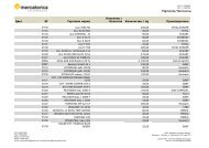
GAS SUPPLY PANELS SMD ´<strong>320</strong>-16/-24/-25Single-stage,for inert, reactive, flammable and oxidizing gases and gas mixtures,purity max. 5.0inlet pressure 230 bar / 3300 psidownstream pressure range 1 - 14 bar / 14 - 200 psioutType -16inSPECIAL FEATURES•Gas supply panel for standard applications (Type -16)Process gas purging (Type -24)Process gas purging and process gas outlet shut-off valve (Type -25)DESCRIPTIONThese gas supply panels are mounted onto a stainless steel panel and consist of a pressure regulator, inlet andoutlet pressure gauges, a relief valve and shut-off valves (type -16 at the outlet, type -24 at the inlet, type -25 at inletand outlet) for the process gas. A choice of stainless steel coils or flexible high pressure hoses is available for theconnection to the gas cylinder. The use of contact gauge (accessories) in conjunction with alarm box (accessories)facilitates the monitoring of gas reserves. Vent piping connected to the relief valve can be ordered optionally.outType -24inAPPLICATIONGas panels are permanently installed in the cylinder stock room or cabinet near the point of use and reduce thecylinder pressure to a lower line pressure. Through the subsequent piping system the gas is taken to the point of use.The type -24 allows for process gas purging to be carried out while cylinders are being changed. The type-25 designallows shutting-off of gas flow during cylinder change from the panel itself. Standard application for these panels:centralized or decentralized gas supply.8outFLOW SCHEMATICType -2596 574 3Type -25shown withoutvent piping1021inTECHNICAL DATABody:stainless steel 316L (1.4404) specially cleaned or brass CW614 (CuZn39Pb3)specially cleaned, nickel-plated and chrome-platedRelief valve:Outlet NPT 1/4"f, downstream pressure > 50 bar RV on requestSeat seals:PCTFEBody seals:PCTFE (SS), PVDF (Brass)Relief valve seat seals: SS: FKM, (EPDM, FFKM)*, Brass: EPDM, (FKM)*Performance data:see the single stage regulatorBasic design aspects: see page 2Pressure gauge range: 0 - 25 bar (0 - 365 psi),0 - 315 bar (0 - 4500 psi)Weight: approx. 2.5 kg (type -16) / 2.74 kg (type -24)/ 3 kg (type -25)Dimensions (w×h×d):approx. 250×155×185 mmPurge outlet:NPT 1/4"f or tube fittingInlet:NPT 1/4"f , M 14×1.5 (optional)*on request1 Cylinder connection2 Coil3 Shut off valve (not Type -16 )4 Pressure regulator - Single-stage5 Upstream pressure gauge6 Downstream pressure gauge7 Process gas outlet shut-off valve(Type -25 and -16)8 Process gas outlet9 Relief valve10 Purge outlet valve (not Type -16 )ORDER CODETypeSMD <strong>320</strong>-16SMD <strong>320</strong>-16SMD <strong>320</strong>-24SMD <strong>320</strong>-25MaterialBCBC = brasschrome-platedSS = stainlesssteelUpstream pressureFF = 230 bar/3300 psiDownstream pressure1414 = 1 - 14 bar/15 - 200 psiInletN14N14 =NPT 1/4"fM14×1.5(optional)OutletCL6 BC0=NPT 1/4"fCL6, CL8**CL10, CL12BC = brasschrome-platedContact gaugeKi0 = withoutKi = withVent pipingA0 = withoutA = with(Only inconjunctionwith RV notavailable forType-16)Gas typeGasIt is necessary to have a gas specific connection to the gas supply for an efficient installation and use of this station, see accessories chapter “cylinder connection FA 500". **Outlet: CL6 = tube fitting for tube 6mm, (0 = without). Please note the "burst rate chart" when choosing the tube fittings in chapter 5.6PleasespecifySubject to change without notice
GAS SUPPLY MANIFOLDS BMD <strong>320</strong>-39outSingle-stage,for inert, reactive, flammable and oxidizing gases and gas mixtures,purity max. 5.0,inlet pressure 230 bar / 3300 psi,preset downstream pressure 14 bar - 200 psiinType -39inSPECIAL FEATURES•Uninterrupted gas supply with semiautomatic switch overIndicator for active cylinderLow gas alarm signal with contact gauges (optional)Upgradable to max. 2×4 cylindersDESCRIPTIONPressure decreases in the active cylinder (or bundle) below a preset level which causes a semi-automatic switch toswitch over to the full cylinder. This is achieved by two integrated pressure regulators (preset to slightly differentdelivery pressure levels), connected at their outlet ports. Moving the lever towards the full bank allows for thedisconnection and replacement of empty cylinders without interruption to the gas flow.The use of contact gauge (accessories) in conjunction with alarm box (accessories) facilitates the monitoring ofgas reserves.FLOW SCHEMATICAPPLICATIONThese gas supply panels, with semi-automatic switch over, are optimally used when it is when uninterupted gassupply is required.784213 6Typ -391 Pressure regulator2 Upstream pressure gauge3 Downstream pressure gauge4 Process gas valve6 Relief valve7 Connection spirals8 Gas cylinderH Change over hand wheelBA Process gas outlet21 478TECHNICAL DATABody:stainless steel 316L (1.4404) specially cleaned or brass CW614 (CuZn39Pb3)specially cleaned, nickel-plated and chrome-platedRelief valve:Outlet NPT 1/4"fBody seals:PCTFE (SS), PVDF (Brass)Seat seals:PCTFERelief valve seat seals: FKM, (EPDM, FFKM)*, EPDM, (FKM)*Pressure gauge range: -1 - 18 bar (-15 - 260 psi)/ 0 - 315 bar (0 - 4500 psi)Dimensions (w×h×d):approx. 400×155×200 mmWeight: approx. 5.0 kg (BMD <strong>320</strong>-39)Preset downstream pressure: 14 bar +/-2 bar ; 200 +/- 30 psiFlow rate: 20 Nm³/h N ²(14 bar - type at 29 bar inlet pressure.)Inlet:NPT 1/4"f , M 14×1.5 (optional)Outlet:NPT 1/4"f, optional tube fitting*on requestSubject to change without noticeORDER CODETypeBMD <strong>320</strong>-39BMD <strong>320</strong>-39MaterialBCBC = brasschrome-platedSS = stainlesssteelUpstreampressureFF = 230 bar/3300 psiDownstreampressure1414 = 14 bar/200 psiInletN14N14 =NPT 1/4"fM14×1.5(optional)OutletCL6 BC0=NPT 1/4"fCL6, CL8**CL10, CL12BC = brasschrome-platedContactgaugeKi0 =withoutKi = withExtension barM0 = withoutM2 = 2×2CylinderM3 = 2×3CylinderM4 = 2×4CylinderGas typeGASIt is necessary to have a gas specific connection to the gas supply for an efficient installation and use of this station, see accessories chapter “cylinder connection FA 500". **Outlet: CL6 = tube fitting for tube 6mm,(0 = without). Please note the "burst rate chart" when choosing the tube fittings in chapter 5.Pleasespecify7