CAE-ECM system for electrochemical technology of parts and tools
CAE-ECM system for electrochemical technology of parts and tools
CAE-ECM system for electrochemical technology of parts and tools

You also want an ePaper? Increase the reach of your titles
YUMPU automatically turns print PDFs into web optimized ePapers that Google loves.
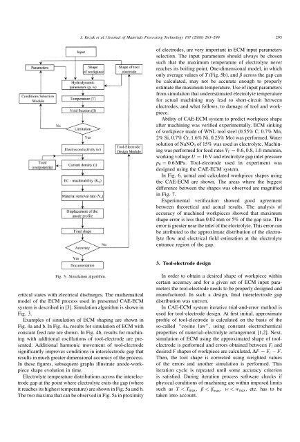
J. Kozak et al. / Journal <strong>of</strong> Materials Processing Technology 107 (2000) 293±299 295<strong>of</strong> electrodes, are very important in <strong>ECM</strong> input parametersselection. The input parameters should always be chosensuch that the maximum temperature <strong>of</strong> electrolyte neverreaches its boiling point. One-dimensional model, in whichonly average values <strong>of</strong> T (Fig. 5b), <strong>and</strong> b across the gap canbe calculated, may not be accurate enough to properlyestimate the maximum temperature. Use <strong>of</strong> input parametersfrom simulation that underestimated electrolyte temperature<strong>for</strong> actual machining may lead to short-circuit betweenelectrodes, <strong>and</strong> what follows, to damage <strong>of</strong> tool <strong>and</strong> workpiece.Ability <strong>of</strong> <strong>CAE</strong>-<strong>ECM</strong> <strong>system</strong> to predict workpiece shapeafter machining was veri®ed experimentally. <strong>ECM</strong> sinking<strong>of</strong> workpiece made <strong>of</strong> WNL tool steel (0.55% C, 0.7% Mn,2% Si, 0.7% Cr, 1.6% Ni, 0.25% Mo) was per<strong>for</strong>med. Watersolution <strong>of</strong> NaNO 3 <strong>of</strong> 15% was used as electrolyte. Machiningwas per<strong>for</strong>med <strong>for</strong> feed rates V f ˆ 0:6, 0.8, 1.0 mm/min,working voltage U ˆ 16 V <strong>and</strong> electrolyte gap inlet pressurep 0 ˆ 0:6 MPa. Tool-electrode used in experiment wasdesigned using the <strong>CAE</strong>-<strong>ECM</strong> <strong>system</strong>.In Fig. 6, actual <strong>and</strong> calculated workpiece shapes usingthe <strong>CAE</strong>-<strong>ECM</strong> are shown. The areas where the biggestdifference between the shapes was observed are magni®edin Fig. 7.Experimental veri®cation showed good agreementbetween theoretical <strong>and</strong> actual results. The analysis <strong>of</strong>accuracy <strong>of</strong> machined workpieces showed that maximumshape error is less than 0.02 mm or 5% <strong>of</strong> the gap size. Theerror is greater near the inlet <strong>of</strong> the electrolyte. This error canbe attributed to the approximate distribution <strong>of</strong> the electrolyte¯ow <strong>and</strong> electrical ®eld estimation at the electrolyteentrance region <strong>of</strong> the gap.3. Tool-electrode designFig. 3. Simulation algorithm.critical states with electrical discharges. The mathematicalmodel <strong>of</strong> the <strong>ECM</strong> process used in presented <strong>CAE</strong>-<strong>ECM</strong><strong>system</strong> is described in [3]. Simulation algorithm is shown inFig. 3.Examples <strong>of</strong> simulation <strong>of</strong> <strong>ECM</strong> shaping are shown inFig. 4a <strong>and</strong> b. In Fig. 4a, results <strong>for</strong> simulation <strong>of</strong> <strong>ECM</strong> withconstant feed rate are shown. In Fig. 4b, results <strong>for</strong> machiningwith additional oscillations <strong>of</strong> tool-electrode are presented.Additional harmonic movement <strong>of</strong> tool-electrodesigni®cantly improves conditions in interelectrode gap thatresults in much greater dimensional accuracy <strong>of</strong> the process.In these ®gures, subsequent graphs illustrate anode-workpieceshape evolution in time.Electrolyte temperature distributions across the interelectrodegap at the point where electrolyte exits the gap (whereit reaches its highest temperature) are shown in Fig. 5a <strong>and</strong> b.The two maxima that can be observed in Fig. 5a in proximityIn order to obtain a desired shape <strong>of</strong> workpiece withincertain accuracy <strong>and</strong> <strong>for</strong> a given set <strong>of</strong> <strong>ECM</strong> input parametersthe tool-electrode needs to be properly designed <strong>and</strong>manufactured. In such a design, ®nal interelectrode gapdistribution was uneven.In <strong>CAE</strong>-<strong>ECM</strong> <strong>system</strong> iterative trial-<strong>and</strong>-error method isused <strong>for</strong> tool-electrode design. At ®rst initial, approximatepro®le <strong>of</strong> tool-electrode is calculated on the basis <strong>of</strong> theso-called ``cosine law'', using constant <strong>electrochemical</strong>properties <strong>of</strong> material±electrolyte arrangement [1,2]. Next,simulation <strong>of</strong> <strong>ECM</strong> using the approximated shape <strong>of</strong> toolelectrodeis per<strong>for</strong>med <strong>and</strong> errors obtained between F i <strong>and</strong>desired F shapes <strong>of</strong> workpiece are calculated, DF ˆ F i F.Then, the tool shape is corrected using weighted values<strong>of</strong> the errors <strong>and</strong> another simulation is per<strong>for</strong>med. Thisiteration cycle is repeated until some accuracy criterionis satis®ed. During iteration process s<strong>of</strong>tware checks ifphysical conditions <strong>of</strong> machining are within imposed limitssuch as T < T max ; b < b max ; w < w max , etc. has to betaken into account.