LUH Switch Without Relay Installation Manual
LUH Switch Without Relay Installation Manual
LUH Switch Without Relay Installation Manual

Create successful ePaper yourself
Turn your PDF publications into a flip-book with our unique Google optimized e-Paper software.
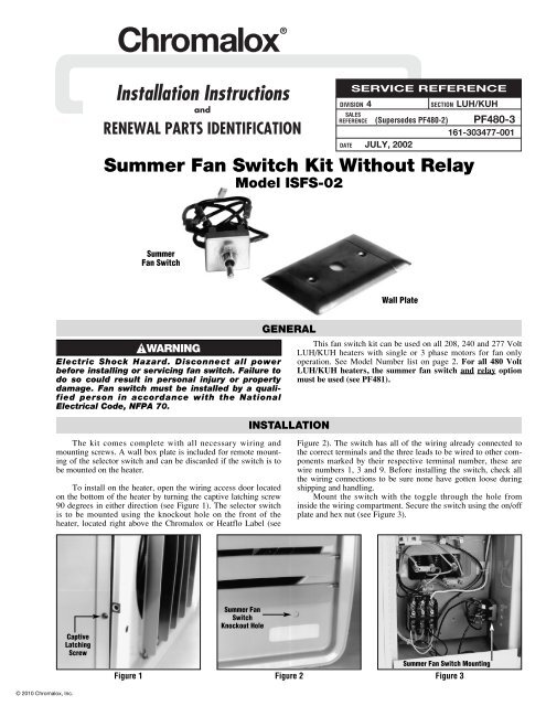
Chromalox ® DIVISION 4 SECTION <strong>LUH</strong>/KUH<strong>Installation</strong> InstructionsandRENEWAL PARTS IDENTIFICATIONSALESREFERENCEDATESERVICE REFERENCE(Supersedes PF480-2) PF480-3161-303477-001JULY, 2002Summer Fan <strong>Switch</strong> Kit <strong>Without</strong> <strong>Relay</strong>Model ISFS-02SummerFan <strong>Switch</strong>Wall PlateElectric Shock Hazard. Disconnect all powerbefore installing or servicing fan switch. Failure todo so could result in personal injury or propertydamage. Fan switch must be installed by a qualifiedperson in accordance with the NationalElectrical Code, NFPA 70.GENERALINSTALLATIONThis fan switch kit can be used on all 208, 240 and 277 Volt<strong>LUH</strong>/KUH heaters with single or 3 phase motors for fan onlyoperation. See Model Number list on page 2. For all 480 Volt<strong>LUH</strong>/KUH heaters, the summer fan switch and relay optionmust be used (see PF481).The kit comes complete with all necessary wiring andmounting screws. A wall box plate is included for remote mountingof the selector switch and can be discarded if the switch is tobe mounted on the heater.To install on the heater, open the wiring access door locatedon the bottom of the heater by turning the captive latching screw90 degrees in either direction (see Figure 1). The selector switchis to be mounted using the knockout hole on the front of theheater, located right above the Chromalox or Heatflo Label (seeFigure 2). The switch has all of the wiring already connected tothe correct terminals and the three leads to be wired to other componentsmarked by their respective terminal number, these arewire numbers 1, 3 and 9. Before installing the switch, check allthe wiring connections to be sure none have gotten loose duringshipping and handling.Mount the switch with the toggle through the hole frominside the wiring compartment. Secure the switch using the on/offplate and hex nut (see Figure 3).CaptiveLatchingScrewSummer Fan<strong>Switch</strong>Knockout HoleSummer Fan <strong>Switch</strong> MountingFigure 1 Figure 2 Figure 3© 2010 Chromalox, Inc.
The basic stock heater wiring diagram (Figure 4) will be changedto the finished diagram (Figure 5).1. Remove the motor lead wires from the heater contactor terminalsmarked T1, T2 and T3. (Note that single phase motors will haveonly two lead wires.)2. Connect the black wire (Number 1) from the switch to the T3 terminalon the heater contactor.3. Connect black wire (Number 3) to contactor terminal marked L3.4. Connect one of the motor leads to terminal 2 on the switch.5. Connect the second motor lead to connector terminal marked L1.WIRINGADDITIONAL STEPS FOR HEATERS WITHTHREE (3) PHASE MOTORS6. Connect black wire (number 9) to contactor terminal marked L2.7. Connect black wire (number 7) to contactor terminal marked T2.8. Connect third motor lead wire to terminal 8 on the switch. Aftercompletion of the heater installation, when the fan circuit is firstturned on, check the rotation of the fan to be sure air is movingfrom the back of the heater to the front. If the air is moving in theopposite direction, interchange any two motor lead connections tocorrect the air flow direction.1 Phase 2 or 3 ElementPri.VoltT1 T2 T3C1L1L33 Phase DeltaT1 T2 T3C1L1 L2 L3Transformer Color Code IndexPri.LeadXFMR 120V Sec. 24V Sec.Clrs. Lead Clrs. Lead Clrs.H1 H2 X1 X2 X1 X2208 WHT BLK RED RED YEL YEL240 WHT RED RED RED YEL YEL277480WHT YELWHT BLUREDREDREDREDYELYELYELYELX1H1X2H2XFMROptional ThermostatBuilt-in or Field InstalledTo Element WiringCutoutT1 T2 T3C1Optional Disconnect <strong>Switch</strong>Built-in or Field InstalledBuilt-in or Field InstalledFactory WiringL3L2L1Motor1Ø or 3Ø3Ø Wiring OnlyPower60HzBuilt-in or Field InstalledFactory WiringOptional ThermostatBuilt-in or Field Installed3 Phase DeltaT1 T2 T3C1L1 L2 L3T1 T2 T3C1L1L3CutoutTo Element Wiring1 2X1 X2 3 Motor7 1Ø or 3ØT1 T2 T39 8XFMR C1 1011 12H1 H21 Phase 2 or 3 Element Optional Disconnect <strong>Switch</strong>Built-in or Field InstalledMotorT1 T2 T3C13Ø Wiring Only1Ø or 3ØStandard Motor ConnectionFigure 4 Figure 5ISFS-02 Kit vs. Applicable Heater Model NumberPri.Volt208240277L3L2L13Ø Wiring OnlyPower60HzTransformer Color Code IndexPri. XFMR 120V Sec.Lead Clrs. Lead Clrs.24VLeadSec.Clrs.H1 H2 X1 X2 X1 X2WHTWHTWHTBLK REDRED REDYEL REDOptional SummerFan <strong>Switch</strong> Built-inor Field InstalledREDREDREDYELYELYELYELYELYELMODELMODELMODELMODEL<strong>LUH</strong>-D-02-81-34-00<strong>LUH</strong>-D-02-21-34-00<strong>LUH</strong>-D-02-71-35-00<strong>LUH</strong>-D-04-81-34-00<strong>LUH</strong>-D-04-83-34-00<strong>LUH</strong>-D-04-21-34-00<strong>LUH</strong>-D-04-23-34-00<strong>LUH</strong>-D-04-71-35-00<strong>LUH</strong>-D-05-81-34-00<strong>LUH</strong>-D-05-83-34-00<strong>LUH</strong>-D-05-21-34-00<strong>LUH</strong>-D-05-23-34-00<strong>LUH</strong>-D-05-71-35-00<strong>LUH</strong>-D-07-81-34-00<strong>LUH</strong>-D-07-83-34-00<strong>LUH</strong>-D-07-21-34-00<strong>LUH</strong>-D-07-23-34-00<strong>LUH</strong>-D-07-71-35-00<strong>LUH</strong>-D-10-81-34-00<strong>LUH</strong>-D-10-83-34-00<strong>LUH</strong>-D-10-21-34-00<strong>LUH</strong>-D-10-23-34-00<strong>LUH</strong>-D-12-83-34-00<strong>LUH</strong>-D-12-23-34-00<strong>LUH</strong>-D-15-83-34-00<strong>LUH</strong>-D-15-23-34-00<strong>LUH</strong>-D-20-23-34-00<strong>LUH</strong>-D-30-83-34-00<strong>LUH</strong>-D-30-23-34-00<strong>LUH</strong>-D-35-23-34-00<strong>LUH</strong>-D-40-23-34-00KUH-C-02-81-00KUH-C-02-21-00KUH-C-02-71-00KUH-C-04-81-00KUH-C-04-83-34KUH-C-04-21-00KUH-C-04-23-34KUH-C-04-71-00KUH-C-05-81-00KUH-C-05-83-34KUH-C-05-21-00KUH-C-05-23-34KUH-C-05-71-00KUH-C-07-81-34KUH-C-07-83-34KUH-C-07-21-34KUH-C-07-23-34KUH-C-07-71-30KUH-C-10-81-34KUH-C-10-83-34KUH-C-10-21-34KUH-C-10-23-34KUH-C-12-83-34KUH-C-12-23-34KUH-C-15-83-34KUH-C-15-23-34KUH-C-20-23-34KUH-C-30-83-34KUH-C-30-23-34KUH-C-35-23-34KUH-C-40-23-34Limited Warranty:Please refer to the Chromalox limited warranty applicable to this product athttp://www.chromalox.com/customer-service/policies/termsofsale.aspx.2150 N. RULON WHITE BLVD., OGDEN, UT 84404Phone: 1-800-368-2493 www.chromalox.com