FAQ's - sebaKMT
FAQ's - sebaKMT
FAQ's - sebaKMT

Create successful ePaper yourself
Turn your PDF publications into a flip-book with our unique Google optimized e-Paper software.
FAQ’s<br />
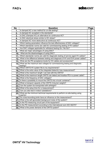
No Question Page<br />
1. Is damped AC a new method for on-site testing? 2<br />
2. Is damped AC accepted in the standards? 2<br />
3. Is DAC (Damped AC) an alternative for continuous AC? 2<br />
4. Is DAC electrical stress similar to DC stress? 2<br />
5. Is damped AC more destructive as continuous AC? 2<br />
6. Which testing parameters influence the test effectiveness of DAC voltages? 2<br />
7. Which standards/ norms are valid for commissioning testing of HV-cables? 3<br />
8. Are DAC voltages applicable for withstand testing Go / No-Go? 3<br />
9. What are major advantages of using DAC? 4<br />
10. What are the disadvantages of using DAC? 4<br />
11. Which standards/ norms are valid for diagnostic testing of service aged HV-cables? 4<br />
12. What is the difference between testing and diagnosis of HV and EVH power cables? 4<br />
13. What are the PD acceptance levels for HV-cables and accessories? 5<br />
14. What are the maximum test voltages for commissioning testing and diagnostic<br />
testing?<br />
5<br />
15. Which OWTS HV system fits to my requirements? 6<br />
16. What is the extra value of the integrated dielectric loss measurement? 6<br />
17. What is the maximum length I can test with the OWTS? 7<br />
18. What is the maximum length OWTS can detect and localize PD in a power cable? 7<br />
19. What is the frequency of DAC voltages? 7<br />
20. Is there a possibility to mount the OWTS into a truck/ container? 7<br />
21. What is transport capacity of the OWTS (Volume/ weight)? 8<br />
22. Can the system be transported with airfreight? 8<br />
23. What is the setup time for a measurement? 8<br />
24. Can you also test in indoor substations? 8<br />
25. What are the minimum technical requirements to perform on-site testing using<br />
OWTS?<br />
9<br />
26. Do cross-bounding joints have an influence on the measurement? 9<br />
27. What is the self generated background noise of the system? 8<br />
28. Is the PD-measuring circuit part of the equipment? 9<br />
29. Is the PD measurement according to the international norm IEC 60270? 9<br />
30. What is the power demand of the OWTS system? 9<br />
OWTS ® HV Technology<br />
1
FAQ’s<br />
1. Is damped AC a new method for on-site testing?<br />
NO: The damped alternating voltage (DAC) is an oscillating switching impulse<br />
voltage (OSI) of quite low damping (
FAQ’s<br />
c) number of DAC voltage excitations appears to be an important parameter; the<br />
breakdown voltage decreases as the number of excitations increases;<br />
d) The DAC voltage charging time does not seem to have an important influence on<br />
the breakdown processes;<br />
7. Which standards/ norms are valid for commissioning testing of HV-cables?<br />
Looking for standards important for on-site testing we have to make a distinction<br />
between HV and EHV cables, HV cables are standardized as cables with a rated<br />
voltage between 30kV and 150kV, EHV for cables with a rated voltage for 150kV and<br />
higher.<br />
Standards for (E) HV cable design and testing are: IEC 60060-3 High Voltage test<br />
techniques –Part 3: Definitions and requirements for on-site testing<br />
[1] IEEE 400 Guide for Field Testing and Evaluation of the Insulation of Shielded<br />
Power Cable Systems<br />
[2] IEEE 400.3 Guide for PD Testing of Shielded Power Cable Systems in a Field<br />
Environment<br />
[3] IEC 60840 Power cables with extruded insulation and the accessories for rated<br />
voltages above 30kV up to 150kV Test methods and requirements;<br />
[4] IEC 62067 Power cables with extruded insulation and the accessories for rated<br />
voltages above 150kV.<br />
In addition with regard to PD detection the following standards are of importance<br />
[5] IEC 60270, Partial Discharges Measurements, 2000<br />
[6] IEC 885-3 Test methods for Partial Discharges measurements on lengths of<br />
extruded power cable<br />
Moreover with regard to on-site testing and diagnosis several Cigre documents have been<br />
published in the past e.g.<br />
[7] CIGRE Electra 176, 1998, ‘’Diagnostic Methods for HV Paper Cables and<br />
Accessories’’<br />
[8] CIGRE Electra 208 Electra, 2003. “Experiences in partial discharge detection of<br />
distribution power cable systems”<br />
[9] CIGRE Brochure 226, 2004, ‘’Knowledge rules for partial discharge diagnosis in<br />
service’’<br />
[10] CIGRE Electra 226, 2006, ‘’Practical aspects of the detection and location of<br />
partial discharges in power cables’’<br />
8. Are DAC voltages applicable for withstand testing Go / No-Go?<br />
YES: Applying DAC withstand test the cable section can be stressed with a selected<br />
DAC voltage stress for selected time duration and the cable section can be rejected if<br />
a breakdown has occurred.<br />
Due to shorter duration of the excitations and decaying characteristic of the voltage it<br />
is not directly comparable to withstand voltage testing with continuous AC.<br />
OWTS ® HV Technology<br />
3
FAQ’s<br />
9. What are major advantages of using DAC?<br />
Application of DAC voltages has the following advantages:<br />
1. Since several years accepted for on-site testing and PD measurements of all<br />
types and lengths of power cables.<br />
2. Simple, lightweight, cost effective equipment with very low input power<br />
requirements and able to stress long cable lengths.<br />
3. With regard to partial discharges similar AC electrical stresses as during factory<br />
testing and service operation.<br />
4. During over-voltage application the small number of cycles reduces the risk of<br />
damage to the cable system.<br />
5. Analyzing the damped AC voltage attenuation provides information about<br />
dielectric losses (tan δ, ∆ tanδ).<br />
10. What are the disadvantages of using DAC?<br />
Actually there are no serious disadvantages in using DAC voltages. A number of<br />
limitations can be mentioned:<br />
1. Due to short duration of the excitations and decaying characteristic of the damped<br />
AC voltage the breakdown field strengths are not directly comparable to the<br />
breakdown stresses of withstand voltage testing with continuous AC.<br />
2. To obtain PD occurrence conditions (e.g. PD inception, PD level) similar to 50<br />
(60) Hz AC voltage stresses, the DAC frequency has to be below approx. 500 Hz.<br />
3. Use of fixed inductor at different cable capacitances results in variation in<br />
resonance frequencies.<br />
4. In the case of very short cable length an additional capacitive load is<br />
recommended.<br />
5. The damped AC voltage decay characteristic depends on the actual dielectric loss<br />
behavior of a particular cable section.<br />
11. Which standards/ norms are valid for diagnostic testing of service aged HVcables?<br />
Generally taken there are no standards/ norms for diagnosing HV-cables. However<br />
experiences from diagnostic testing in the MV-network of over 10 years have proven<br />
the need for diagnosis. When performing diagnostic testing one can monitor the<br />
condition of the insulation, in other words follow the ageing processes of the<br />
insulation. In the HV-application this is very useful to monitor oil-filled, oil-pressurized<br />
or gas pressurized cables. From this type of cable it is generally known that they<br />
show higher dielectric losses due to ageing and are reaching the end of there<br />
estimated life time, so what to do with these cables?<br />
12. What is the difference between testing and diagnosis of HV and EVH power<br />
cables?<br />
With regard to testing the following is important:<br />
1. To detect insulation defects in HV and EHV power cables during on-site testing<br />
voltages higher than Uo (over-voltages) can be used.<br />
2. Voltage tests up to e.g. 1.7Uo to demonstrate that<br />
OWTS ® HV Technology<br />
4
FAQ’s<br />
a. the insulation is healthy (defect-free and/or non-aged) and that insulation<br />
can withstand a high voltage stress level,<br />
b. insulation is aged and/or consists of insulation defects should<br />
have lower level of withstand voltage.<br />
With regard to diagnosis the following is important:<br />
1. PD detection up to e.g. 1.7Uo to demonstrate that the insulation is PD free by<br />
determining the PDIV. The margin between PDIV and the Uo is a reliability<br />
indicator of a particular cable circuit.<br />
2. With regard to service aged power cables the dielectric loss measurement in<br />
function of the test voltage up to e.g. 1.7Uo is very valuable indicator about the<br />
thermal stability of a particular cable circuit (OF cables).<br />
13. What are the PD acceptance levels for HV-cables and accessories?<br />
Generally speaking HV-XLPE cables and accessories must be PD-free, not only in<br />
case of newly installed cables but also for service aged cables.<br />
Oil filled cables should be also PD-free, but at field tests some test objects have<br />
shown PD in terminations and cable insulation. Today no threshold values for<br />
acceptable PD level in oil filled cables are known.<br />
14. What are the maximum test voltages for commissioning testing and<br />
diagnostic testing?<br />
When testing in accordance to the IEC 60840 for cables rated up to 150kV the<br />
specified test voltages are listed below:<br />
OWTS ® HV Technology<br />
5
FAQ’s<br />
For cables rated higher then 150kV the test voltage has to be selected in accordance<br />
to IEC 62067<br />
or with 1.7U0, depending on practical operational conditions.<br />
15. Which OWTS HV system fits to my requirements?<br />
Depending on the maximum test voltages of a particular cable type a system can be<br />
selected from the table below<br />
OWTS ® HV Technology<br />
Applicability for testing different power cable ratting voltages<br />
Power cable rated Uo [kV] OWTS HV 150 OWTS HV 250 OWTS HV 350<br />
voltages [kV]<br />
X Uo<br />
X Uo<br />
X Uo<br />
66 38,1 2,8<br />
110 63,5 1,7 2,8<br />
132 76,2 1,4 2,3<br />
150 86,6 1,2 2.0 2,8<br />
220 127 0.8 1,4 1,9<br />
330 190,5 0.9 1,3<br />
380 219,4 1,1<br />
16. What is the extra value of the integrated dielectric loss measurement?<br />
The estimation of the dielectric losses which has been integrated in the OWTS<br />
determines the condition of the insulation and is therefore for HV-cables of major<br />
importance. Especially for HV-cables with paper insulation such as; oil filled cables,<br />
oil-pressurized or gas-pressurized cables, the dielectric losses (absolute and tip-up)<br />
is an important parameter.<br />
6
FAQ’s<br />
17. What is the maximum length I can test with the OWTS?<br />
OWTS HV technology is standard tested for capacitive loads of cable lengths up to<br />
30km) and longer. On request larger capacitive loads can also be also energized.<br />
Depending on the type of cable the capacitance per kilometre differs. For instance a<br />
XLPE insulated cable with a specific capacitance of 200 nF/km can have a length of<br />
40 km.<br />
18. What is the maximum length OWTS can detect and localize PD in a power<br />
cable?<br />
A distinction has to be made between PD-detection and PD-localisation. The OWTS<br />
is the only an integrated system available which is able to energize and detect PD<br />
from cables up to capacitive load of cable lengths to 30km) and longer.<br />
Using IEC60270 PD detection principles OWTS is the best system to detect on-site in<br />
[pC] very sensitively PD in all type of power cables.<br />
To localize PD sites in a power cable OWTS uses the time domain reflectometry<br />
method. It is known that TDR effectiveness depends on several factors e.g.<br />
a) HF-impedance characteristic of the particular cable system<br />
b) PD site position in the cables<br />
c) PD level and intensity<br />
d) actual background noise,<br />
e) PD level etc.<br />
Therefore it is not possible to give a fixed number of max. length to localize PD sites.<br />
It is advisable in the case of long cables to perform PD detection form both cable<br />
ends.<br />
19. What is the frequency of DAC voltages?<br />
OWTS uses large PD-free and low losses inductors specially developed for testing<br />
power cables. Depending on the type of OWTS system the inductors may vary<br />
between 4H and 8H. As a result the frequency of the DAC wave will be between<br />
20Hz and 300Hz, which is the normalized frequency according to the IEC standards<br />
IEC 62067 and IEC 60840. The particular DAC frequency is depending on the length<br />
of the cable section under test. In particular after charging the cable section up to<br />
selected voltage level the LC circuit as obtained from the cable capacitance and the<br />
external inductance (7H) As a result system produces sinusoidal damped AC<br />
voltages in the range of 20Hz-300Hz, depending on cable capacitance.<br />
Examples of typical damped ac voltage frequencies for different lengths of two typical 150kv<br />
power cables<br />
Length [km] XLPE (C=154pF/m) [Hz] Oil filled (C=373pF/m) [Hz]<br />
0.25 300 194<br />
0.5 213 137<br />
1 151 97<br />
2 107 69<br />
4 76 49<br />
8 53 34<br />
16 38 24<br />
20 34 22<br />
20. Is there a possibility to mount the OWTS into a truck/ container?<br />
YES: The OWTS has been originally designed to be transportable, that’s why the<br />
components have been packed in transportation boxes. However mounting the<br />
OWTS 150kV in a container must be possible.<br />
7<br />
OWTS ® HV Technology
FAQ’s<br />
For the other two systems (HV250 and HV350) this will bring implications since the<br />
height of the system + clearance will be more then 4m, which makes transportation<br />
on road or by rail problematic.<br />
The systems can be mounted on a trailer of sufficient length. In this case extra<br />
measures have to be taken to support the individual components during transport.<br />
21. What is transport capacity of the OWTS (Volume/ weight)?<br />
In the table listed below the total volume of each system has been given. When<br />
compared with a resonance test set this is almost nothing.<br />
OWTS HV 150kV 10 m 3<br />
OWTS HV 250kV 12 m 3<br />
OWTS HV 350kV 20 m 3<br />
E.g. for the OWTS HV 150 system for transportation purpose the minimal cubic size<br />
must be 10m3 Vans like: Mercedes Sprinter 311, Opel Movano L2H2<br />
Component Height (cm) Width (cm) Length (cm) Net weight<br />
3 x coil box 65 75 75 45kg<br />
Bas unit box 91 130 85 35kg<br />
HV source box 137 105 75 85kg<br />
PD divider box 115 70 70 45kg<br />
22. Can the system be transported with airfreight?<br />
YES: all system of the OWTS technology can be transported with airfreight.<br />
Since the weight and size of the equipment are both relatively small it is possible to<br />
transport the system by airfreight. Something that isn’t possible with a resonance test<br />
set).<br />
23. What is the setup time for a measurement?<br />
The setup of the system is one of the most important aspects of the entire<br />
measurement and must therefore be done carefully. Generally it takes up to 2 hours<br />
to setup the system, required that all other work like de-energizing the cable and<br />
making the termination free for connecting the OWTS on it, is performed on forehand.<br />
E.g. Un-packing/packing OWTS HV 150 components and connection to the test<br />
object: approx. 2.0 hrs.<br />
Measuring (one phase) depending on max test voltage applied, e.g. starting from 10<br />
kV (peak) to 150 kV (peak) with steps 10kV, testing/measurement takes: approx.<br />
0.5hrs/phase. Changing between particular cable phases approx. 2x 0.5hrs<br />
Total duration: Depending on cable section detailed information, logistics and on-site<br />
local situation and the amount of diagnostic data to be collected for 3-phase cable<br />
approx. 5-8 hrs.<br />
24. Can you also test in indoor substations?<br />
YES: One of the big advantages of the OWTSHV Technology is the compactness of<br />
the system. Since the dimensions of the OWTS HV series are relatively small, it is<br />
absolutely no problem to measure indoor. Each component has been packed in a<br />
portable transportation box on wheels which makes it possible to easily transport the<br />
equipment to the measurement side.<br />
OWTS ® HV Technology<br />
8
FAQ’s<br />
25. What are the minimum technical requirements to perform on-site testing<br />
using OWTS?<br />
There are no special or extraordinary requirements regarding testing using OWTS.<br />
Preparing the on-site test the following has to be considered:<br />
1. At the location a power supply of 220Vac 50(60Hz and rated for at least 5kW has<br />
to be available.<br />
2. The access to the test object (connection point between the OWTS system and<br />
the cable terminations) has to be below 7m height.<br />
3. The test object has fully be disconnected from the network and other components<br />
e.g. transformers, surge arrestors etc.<br />
4. In the case of GIS connection the specific tools (inserts, bushings, etc) needed to<br />
connect the test system has to be provided and installed by the customer.<br />
5. Tent of other solution needed to protect the test system against the rainwater.<br />
6. In case of an higher position of the termination (more than 5-7m) a special pd free<br />
connecting cable is required.<br />
26. Do cross- bonding joints have an influence on the measurement?<br />
YES: Cross-bonding joints have an influence on the signal quality of the travelled PD<br />
pulses. Cross links must therefore be removed and sheaths must be connected<br />
normal during PD-testing.<br />
27. What is the self generated background noise of the system?<br />
Since the voltage source is disabled during the PD measuring, DAC principle, the self<br />
generated background-noise of the system can be assumed as