Low Voltage circuit-breaker breaking techniques - Schneider Electric
Low Voltage circuit-breaker breaking techniques - Schneider Electric
Low Voltage circuit-breaker breaking techniques - Schneider Electric
- No tags were found...

Create successful ePaper yourself
Turn your PDF publications into a flip-book with our unique Google optimized e-Paper software.
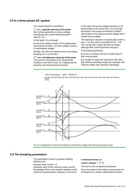
5.5 In a three-phase AC systemTwo cases should be considered:1 st case: separate opening of the polesEach phase generates an arcing voltageaccording to the current flowing through it(see fig. 20 ).At first sight, it is as though:c one of the phases breaks in the single-phasesymmetrical condition, but with voltage recoveryin intermediate voltage;c finally, the other two phases ensure two-phase<strong>breaking</strong> of a «current tail».2 nd case: simultaneous opening of the polesThe current of the phase in the symmetricalcondition is the first to react on a tripping deviceensuring very fast opening of all poles.In this case, the arcing voltages develop on allthree phases at the same time. It is as thoughthe phase in the quasi-symmetrical conditionwere broken in its phase-to-phase voltage with adouble arcing voltage.The opening of all poles must take place within atime < T/4 and will be most efficient for < T/8.The «small loop» phase will then be brokenalthough little current has flown through it.This <strong>breaking</strong> behaviour:c occurs on devices with low overall inertia oftheir moving parts;c is sought on large-size equipment with ultrafastexternal operating energy (for example, withThomson effect with capacitive discharge).VOLTA laboratory A0201 89/02/0141 msip1channel 120 kAchannel 4200 VI 1V 1channel 220 kAchannel 5200 VI 2V 2ip2channel 320 kAchannel 6200 VI 3V 3Fig. 20: oscillograms for test <strong>circuit</strong> <strong>breaking</strong> in three-phase voltage with separate opening of poles.5.6 The <strong>breaking</strong> parametersThe parameters chosen to assess <strong>breaking</strong>efficiency are:c broken peak current = îc(absolute value of the maximum peak current)Knowledge of this value enables definition of themaximum electrodynamic stresses in the <strong>circuit</strong>;c «thermal stress» or2Joule's integral = i dt∫This term is the recognised expression.Since the shape of the broken current does notcorrespond to a simple mathematical function,Cahier Technique <strong>Schneider</strong> <strong>Electric</strong> no. 154 / p.17