this integral is calculated step-by-step bycomputer.This integral expresses both thermal andelectrodynamic energy stresses on the <strong>circuit</strong>elements;c <strong>breaking</strong> time = t aTotal <strong>breaking</strong> time if the <strong>circuit</strong> is three-phase;c maximum arc voltage = U aMagnitude :v 250 to 500 V for standard <strong>circuit</strong>-<strong>breaker</strong>s,v 600 to 900 V for limiting <strong>circuit</strong>-<strong>breaker</strong>s.These «overvoltages» do not presenta risk since they are lower than thetest voltages standardised for LVinstallations;c arc energy =∫u a i a dtThis integral is also calculated step-by-stepby computer and expresses the energyconsumed in the arcing zone.Magnitude: 1, 10, 100 kJ according to thedevice and the currents broken.It conditions device <strong>breaking</strong> endurance.5.7 Fuse <strong>breaking</strong> techniqueA fuse breaks because of the arc.Its relative simplicity lies in the fact that acarefully calculated filament is brought to itsmelting temperature by the current flowingthrough it.For high currents, the temperature rise resultingin filament melting is of the adiabatic type; itspre-arcing energy is defined by the formula:t paR i 2∫ dt = m c T0fwhere R = filament resistance,m = filament mass,c = thermal capacity,T f= melting temperature,t pa= prearcing time.This «prearcing» thermal energy is separatefrom mains voltage.The arc quickly assumes the length of the meltedfilament and the arcing voltage takes on a valuein accordance with this length and the pressureappearing in the <strong>breaking</strong> unit(see fig. 21 ).This <strong>breaking</strong> unit can be filled with silica powderwhich, as it melts, will absorb the arcing energy.Note: the current "tail" is explained by the«preferential» path created by the arc in themelted silica. The arc decreases in size againstthe walls which are still warm.A few remarks about fuses:c their action is restricted to high overload andshort-<strong>circuit</strong> currents;c some types of fuses have strikers for meltindication purposes, as well sometimes as toindirectly act on an extra <strong>breaking</strong> device toensure opening of all phases;c following a fuse fault and melt, some«survivors» may have come close to melting andtheir characteristics may be altered. They maythen melt inopportunely under a current lowerthan their rating. All fuses must therefore bereplaced at the same time.ii p,,,,, @@@@@ €€€€€ ÀÀÀÀÀ,,,,, @@@@@ €€€€€ ÀÀÀÀÀ,,,,, @@@@@ €€€€€ ÀÀÀÀÀ,,,,, @@@@@ €€€€€ ÀÀÀÀÀ,,,,, @@@@@ €€€€€ ÀÀÀÀÀ,,,,, @@@@@ €€€€€ ÀÀÀÀÀFuse linkSilicaInsulating enclosureConnection devicet paUaUrttUii aFig. 21: the fuse, its composition and its characteristic <strong>breaking</strong> curves.tCahier Technique <strong>Schneider</strong> <strong>Electric</strong> no. 154 / p.18
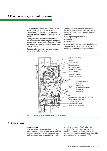
6 The low voltage <strong>circuit</strong>-<strong>breaker</strong>A <strong>circuit</strong>-<strong>breaker</strong> (see fig. 22 ) is a connectiondevice able to close and break a <strong>circuit</strong>irrespective of current up to its ultimate<strong>breaking</strong> capacity: Icu (refer to standard IEC60947-2).Although its main function is to break short<strong>circuit</strong>and overload currents by self-energized«reflex» action, it also breaks «normal» currentsand overload currents by voluntary action fromexternal sources.Moreover, after opening, it provides voltageinsulation of the broken <strong>circuit</strong>.The <strong>circuit</strong>-<strong>breaker</strong>'s design enabling it tohouse all these functions in the same casehas led to the adoption of specific solutionsregarding:c closing/opening mechanisms;c trip units;c pole <strong>circuit</strong>s ;c <strong>breaking</strong> elements (contacts, arc chutes...).The purpose of this chapter is to analyse itsfunctions, technologies and performances.Fig. 22: cross-section of an industrial 400 A LV <strong>circuit</strong>-<strong>breaker</strong>.6.1 Its functionsCircuit closingBy action on the closing mechanism, currentflows to supply the load as soon as the slightestcontact is established. When energized, someloads absorb currents far greater than ratedcurrent In (e.g. motor 7 to 8 In for a fewseconds). To prevent these overcurrentsresulting in dangerous phenomena for thecontact zone (erosion by arcs), closing must beprompt, especially for values ≥ 100A.Cahier Technique <strong>Schneider</strong> <strong>Electric</strong> no. 154 / p.19