TracPhone V7 Technician's Pocket Guide - Yachtronics
TracPhone V7 Technician's Pocket Guide - Yachtronics
TracPhone V7 Technician's Pocket Guide - Yachtronics
- No tags were found...

You also want an ePaper? Increase the reach of your titles
YUMPU automatically turns print PDFs into web optimized ePapers that Google loves.
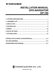
Important Safety InformationWarning - Risk of Electric ShockPotentially lethal voltages are present within the controlunit and the modem. To avoid electrical shock, donot open the chassis enclosures of the belowdecksequipment. They contain no replaceable parts.Warning - RF Radiation HazardBefore removing the antenna’s radome, unplug both thecontrol unit and modem, and make sure power remainsdisconnected while you are working. The antennatransmits RF energy that might cause injury, particularly ifyou are standing near the front of the reflector.Caution - RF Radiation HazardTo avoid potentially harmful exposure to RF radiation,make sure everyone keeps a safe distance away from theantenna while it is operating. Within the antenna’s5-80° elevation range, safe distance is 36 feet (11 m). Nohazard exists directly above the antenna and anywherebelow the antenna’s mounting plane.80RadiationHazard80RadiationHazard536 ft (11 m)Antenna36 ft (11 m)52 <strong>TracPhone</strong> <strong>V7</strong> Technician’s <strong>Pocket</strong> <strong>Guide</strong>
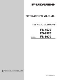
System OverviewThe <strong>TracPhone</strong> <strong>V7</strong> is a fully integrated maritime satellitecommunications system for the mini-VSAT Broadband smservice. Its spread-spectrum technology providesexceptional network performance, while using an antennathat is significantly smaller than traditional VSAT antennas.The system connects to a land-based hub via a Ku-bandsatellite. The hub then provides the Internet link, asmanaged by the Network Operations Center.Ku-Band Satellitemini-VSATConnection<strong>TracPhone</strong>AntennaHubControl Unit& ModemInternetNetwork & VoIPDevicesNetworkOperationsCenter (NOC)Ethernet ConnectionVoIP ConnectionCustomer-SuppliedLaptop PCWAPAnalog PhoneFax Machine<strong>TracPhone</strong> <strong>V7</strong> Technician’s <strong>Pocket</strong> <strong>Guide</strong> 3
Information Dimensions For Your - Antenna Customer27.36"(69.5 cm)26.2"(66.5 cm)12"(30.5 cm)6"(15.2 cm)FWD6"(15.2 cm)12"(30.5 cm)26.2"(66.5 cm)4 x Ø1/2"(Ø13 mm)4 <strong>TracPhone</strong> <strong>V7</strong> Technician’s <strong>Pocket</strong> <strong>Guide</strong>
Dimensions - Belowdecks EquipmentControl Unit or Modem (Identical in Size)2.61"(6.6 cm)16.75"(42.5 cm)11.31"(28.7 cm)Optional Case (6U Height)11.3"(28.7 cm)20.5"(52.1 cm)20.5"(52.1 cm)Switch: 6.7" x 3.9" x 1.1" (17 cm x 9.9 cm x 2.8 cm)MTA: 4.6" x 5.12" x 1.18" (11.7 cm x 13 cm x 3 cm)RSM: 5.12" x 3.54" x 1.5" (13 cm x 9 cm x 3.8 cm)<strong>TracPhone</strong> <strong>V7</strong> Technician’s <strong>Pocket</strong> <strong>Guide</strong> 5
Antenna MountingAntenna Forward ArrowPoint arrow toward the bow, parallel to vessel centerline.Antenna Mounting Hardware3/8"-16 Bolt (x4)3/8" Flat Washer (x4)Antenna BaseplateFoam SealMounting Surface3/8" Shoulder Washer (x4)3/8" Flat Washer (x4)3/8" Lock Washer (x4)3/8"-16 Hex Nut (x4)12-16 ft-lbs (16.2-21.7 N-m) of torque<strong>TracPhone</strong> <strong>V7</strong> Technician’s <strong>Pocket</strong> <strong>Guide</strong> 7
Antenna Data/Power WiresThe diagram refers to wires by body color/stripe color.Terminals #3 and #8 are not used.AntennaTerminal Strip Connector1 2 3 4 5 6 7 8 9 10 11 12PowerRedBlack42 VDCGroundPort 1,Tx+Port 1,Tx-Port 1,Rx+Port 1,Rx-Port 2,Tx+Port 2,Tx-Port 2,Rx+Port 2,Rx-DataWhite/GrayGray/WhiteWhite/OrangeOrange/WhiteWhite/BrownBrown/WhiteWhite/BlueBlue/White100 ft (30 m) data/power cables are supplied in the kit.150 ft (45 m) cables may be purchased separately:Data cable: KVH part #32-0921-0150Power cable: KVH part #32-0924-015010 <strong>TracPhone</strong> <strong>V7</strong> Technician’s <strong>Pocket</strong> <strong>Guide</strong>
Wiring DiagramAntennaNote: Supplied networkand VoIP equipment maydiffer from the switch andMTA models shown here.MRxMTxDataPowerControl UnitMAINTENANCE PORTMaintenance RS232 PortRed (+42V)Black (Gnd)Not UsedANTENNAWht/GryGry/WhtWht/OrgOrg/WhtNot UsedWht/BrnBrn/WhtWht/BluBlu/WhtWire Colors:Body/StripeMODEMModemRS422POWERBUC 20V Power2.5AAntennaPowerGP10SerialRemote Service ModulePowerModemBUC PwrPowerJ6BUC PWRJ1J3J2J5AC PWR Rx RFRx RF Tx RF CONSOLEMODEL: VMBR-1510 ArcLightPART: 1234567 REV XXXJ4SERIAL: XX-XXXXXXACUCAGE CODE: 12345ACUJ8USERUserENET CAUTIONEnetNO OPERATORJ7SERVICEABLEACUPARTS INSIDE,ENETDO NOT OPENNot UsedSwitchLaptopPC768 7 6 554 3 2 1POE48V+PowerPowerMTAWAN12V DC RSTR WAN LAN PHONE 2 PHONE 1Phone1AnalogPhone<strong>TracPhone</strong> <strong>V7</strong> Technician’s <strong>Pocket</strong> <strong>Guide</strong> 11
RF Cable RequirementsUse the proper 75W cable type listed below for your cablerun, and terminate the cable with “F” connectors using theproper tools:15-50 feet (5-15 meters)Cable: RG-11Connector: SNS11AS*Installation Tools: CST596711 and L3011B*51-100 feet (16-30 meters)Cable: LMR-400-75**Connector: EZ-400-FMH-75**Installation Tools: TK-400EZ-75**101-150 feet (31-45 meters)Cable: LMR-600-75**Connector: EZ-600-FMH-75**Installation Tools: TK-600EZ*** Thomas & Betts part numbers** Times Microwave part numbersThe “TK” tool kitsinclude tools forcutting the cable(A), stripping theend of the cable (B),deburring the centerconductor (C), andcrimping on theconnector ferrule (D).Note: For alternative cable options, refer to the Application Notessection of the KVH Partner Portal.12 <strong>TracPhone</strong> <strong>V7</strong> Technician’s <strong>Pocket</strong> <strong>Guide</strong>DACB
J1J3AC PWR Rx RFJ2Tx RFMODEL: VMBR-1510 ArcLightPART: 1234567 REV XXXSERIAL: XX-XXXXXXCAGE CODE: 1234512V DC RSTR WAN LAN PHONE 2 PHONE 1Antenna On/Off AudioSIMPowerJ5CONSOLEJ4ACUJ6BUC PWRJ8USERENETJ7ACUENETNO OPERATORSERVICEABLEPARTS INSIDE,DO NOT OPENPower and GroundingControl UnitModemCAUTIONPowerStripMTAAC/DCAdapterSwitch8 7 6 54 3 2 1POE48V+AC/DCAdapterRemote Service ModuleAC/DCAdapterVessel AC Power(115 or 230 VAC)UPS RecommendedImportant!• Disconnect vessel power before connecting cables;double-check all wiring before reapplying power.• Do not cut off the ground pin from the power plugs, anddo not use 3-prong to 2-prong adapters.• Be sure the vessel is properly grounded in accordancewith marine standards.<strong>TracPhone</strong> <strong>V7</strong> Technician’s <strong>Pocket</strong> <strong>Guide</strong> 13
Installation ChecklistAntenna55You mounted the antenna in a blockage-free area; ithas a clear view of the sky.55You mounted the antenna away from other antennasand outside the beam path of the radar.55You mounted the antenna to a flat and level surfacethat can support the antenna’s weight (60 lbs, 27.3 kg)and withstand heavy vibration.55You mounted the antenna high above all crew andpassenger areas to avoid RF radiation exposure.55You mounted the antenna so its “Forward” arrow pointstoward the bow and is parallel to the centerline.55You removed the shipping restraints inside the antenna:4 bolts (azimuth), 1 wire (elevation), 1 tie-wrap (LNB).55You installed the foam seal around the cable accesshole to prevent water from seeping into the vessel.Belowdecks Equipment55You installed all belowdecks components in a drylocation that provides plenty of ventilation.55You installed the modem and control unit in a locationthat allows easy access to their front panels.55You placed the remote service module in a location thatprovides good GPRS cellular reception.55If the customer has a wireless access point (WAP), youplaced it in a location that provides good WiFi reception.14 <strong>TracPhone</strong> <strong>V7</strong> Technician’s <strong>Pocket</strong> <strong>Guide</strong>
Installation ChecklistWiring55You used appropriate 75W RF cables for your cable run(see page 12) and terminated them using the proper “F”connectors and tools.55You verified all wiring conforms to the wiring diagram.Be sure you did not accidentally reverse the transmit(TX) and receive (RX) cables at the modem.55You strain-relieved all wires and made service loops.55You used straight-through (not crossover) Ethernetcables to connect the switch and the MTA.55You verified the vessel is properly grounded inaccordance with marine standards.Configuration55You verified the latest software versions are installed.55You configured RF radiation hazard zones according tothe customer’s requirements (see page 17).55You configured the TCP/IP properties on the customer’snetworked computer(s) (see page 18).55If the customer has a WAP, you applied securityfeatures to protect the customer’s wireless network.Testing and Delivery55You checked all status indicators and tested the systemby connecting to http://208.83.165.11/mbbtest.55You educated the customer about service activation,usage, and fees.<strong>TracPhone</strong> <strong>V7</strong> Technician’s <strong>Pocket</strong> <strong>Guide</strong> 15
Menu OptionsPress xEXIT to exit menuMODEM STATUSNEXT MENUDIAGNOSTICSNEXT MENUACCEPTANTENNA STATUSNEXT MENU ACCEPTCONFIGURATIONNEXT MENUACCEPTACCEPTMain MenuPRESS TO VIEWEACH MODEM ITEMPRESS TO VIEWEACH ANTENNA ITEMBRIGHTNESS= HIGHNEXT MENU CHANGESET HAZARD ZONE= NONEXT MENU CHANGEDVB ASSIST= OFFNEXT MENU CHANGEFACTORY RESET= NONEXT MENU CHANGECAL GYRO= NONEXT MENUCHANGEMODEM STATEONLINEView modem statusANTENNA STATETRACKINGView antenna statusBRIGHTNESS= MEDIUM?CHANGE ACCEPTSet LCD brightnessSET HAZARD ZONE=YES?CHANGE ACCEPTSet up 2 hazard zonesand inhibit/allow transmitDVB ASSIST= ON?CHANGE ACCEPTSet antenna search modeWith or without DVB-AssistFACTORY RESET= YES?CHANGE ACCEPTReset system to factoryClears RF hazard zonesCAL GYRO= YES?CHANGE ACCEPTCalibrate antenna gyrosVessel must be stationary16 <strong>TracPhone</strong> <strong>V7</strong> Technician’s <strong>Pocket</strong> <strong>Guide</strong>
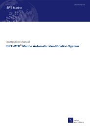
RF Hazard Zones (Optional)You can program up to twoRF hazard zones. Transmitteris inhibited whenever theantenna points within a zone.Hazard Zone335000025315 Forward 0451. Select “Set Hazard Zone”from the control unit’sConfiguration menu.270Antenna0902. Set each zone to a range(>4°) of azimuth bearingsrelative to the antenna’s“Forward” arrow (bow);zones cannot overlap.3. Set “XMT in Zones” to NO.225180135ZONE 1= 335-025?CHANGE ACCEPTZONE 2= 999-999CHANGE ACCEPTXMT IN ZONES= NONEXT ITEM CHANGERF Hazard ZoneAntenna335025<strong>TracPhone</strong> <strong>V7</strong> Technician’s <strong>Pocket</strong> <strong>Guide</strong> 17
PC SetupConfigure the TCP/IP properties on the customer’scomputer(s).DHCP Addressing - Standard ConfigurationStatic IP Addressing - Optional ConfigurationTo request a static IP address, the customer must fill outthe online form at www.kvh.com/mvbservice.*Private IP AddressPrivate IP SubnetPrivate IP GatewayNote: Sampledata providedfor illustrationpurposes only.Private IP Gateway* A one-time setup fee will apply.18 <strong>TracPhone</strong> <strong>V7</strong> Technician’s <strong>Pocket</strong> <strong>Guide</strong>
Startup ScreensANTENNA INITIALIZINGGPS: ACQUIRED41.1N, 72.3WANTENNA READYWAITING FOR MODEMMODEM COMMS: OKRECEIVING SATELLITEINFO FROM MODEMSEARCHING FOR 83.0WDVB-ASSIST SATELLITETRACKING 83.0WDVB-ASSIST SATELLITESEARCHING FOR 72.0WSERVICE SATELLITETRACKING 72.0WSERVICE SATELLITEWhen system is turned on,antenna first runs a self test.Once GPS acquires a fix,displays vessel position.Antenna waits for the modemto initialize.Modem starts communicatingwith the control unit.Modem sends satellite ID datato the antenna.Antenna searches for the DVB-Assist* satellite (varies).Antenna finds, identifies, thentracks the DVB-Assist* satellite.Antenna searches for theservice satellite (varies).Antenna begins tracking theservice satellite.Modem accesses themini-VSAT Broadband service.* Not displayed if DVB-Assist search mode is set to OFF.<strong>TracPhone</strong> <strong>V7</strong> Technician’s <strong>Pocket</strong> <strong>Guide</strong> 19
Status LightsControl Unit LEDOff = Control unit powered offGreen = Good input powerOrange = Bad control unitRed = Error; reboot control unitControl UnitAntenna LEDOff = No antenna powerGreen = Tracking a satelliteGreen, flashing = Antenna searching or modem initializingRed = Error; check error messageModem LEDOff = Modem powered off or initializingGreen = OnlineGreen, flashing = Sending data to antenna, not yet onlineOrange = Error; check error messageRed = No comms; check wiringModemStatus LEDOff = Modem powered off or initializingGreen = OnlineGreen or orange, flashing = Transmitting data or logging inRed = Error if lit while antenna is tracking; reboot modem20 <strong>TracPhone</strong> <strong>V7</strong> Technician’s <strong>Pocket</strong> <strong>Guide</strong>
Status InformationOn any networked computer, enter http://192.168.0.1 intothe web browser to access the modem’s status page.<strong>TracPhone</strong> <strong>V7</strong> Technician’s <strong>Pocket</strong> <strong>Guide</strong> 21
Status InformationLoginFieldTerminal IDLogin StateStateBB Messages RxSerial Number*Software VersionForward LinkFieldEb/NoFLR Packets RxDropped (CRC)Return LinkFieldAttenuationIP Packets TxDescriptionLatter half of modem’s satellite IPaddress: 10.61.x.xLogged In = Connected to networkTransmit Enabled = OK to transmit;Transmit Disabled = Restricted areaShould increment while logged inModem serial numberModem software versionDescriptionShould be at least 2 dB; No Lockindicates blockage or searchingShould increment while logged inShould not increment significantlyDescriptionLower number = higher transmitpower; typically between 8-32 dBShould increment while logged in* Serial numbers for the antenna and control unit (ACU) areprovided on the ACU Status page (select the “ACU/Antenna” link).22 <strong>TracPhone</strong> <strong>V7</strong> Technician’s <strong>Pocket</strong> <strong>Guide</strong>
Status InformationPositionalFieldLatitude/LongitudeSatellite LongitudeSatellite HandoffStatusSatellite HandoffDistanceHardwareFieldACU StateACU StatusChassisTemperatureTXR Fan SpeedDescriptionVessel position reported byantenna’s GPS**Orbital slot of the current satellite**Handoff satellite available = Anadjacent satellite footprint overlapsthe current satellite footprintNumber of miles to the nearestboundary of the current footprintDescriptionOnline Tx = Antenna is tracking thesatellite, transmit OK;Online Tx Inhibit = Antenna istracking, but transmit inhibited;Signal Acquisition = Antenna issearching for the satellite;Offline = Antenna comms lostAll should be lit green; mouse overany red LED to identify its faultTemperature (°C) inside the modemSpeed of modem’s cooling fan;0 rpm indicates fan failure** Negative longitude = West of the prime meridian;Negative latitude = South of the equator<strong>TracPhone</strong> <strong>V7</strong> Technician’s <strong>Pocket</strong> <strong>Guide</strong> 23
HubMiami, FL, USALaurel, MD, USACarlsbad, CA, USAOahu, HI, USATurin, ItalyYokohama, JapanPerth, AustraliaJohannesburg, RSAService HubsThe following hubs provide Internet access via themini-VSAT Broadband service.Coverage AreaCaribbeanNorth AtlanticContinental U.S.North PacificEurope, Middle East, AsiaAsia-Pacific, IndiaAustralia, New ZealandWestern Africa, South AfricaNote: KVH continues to add hubs and expand coverage areas.Use the blanks above to enter new hubs as needed.The latest hub information is available on the KVH PartnerPortal at www.kvh.com/partners.The latest coverage map is available atwww.kvh.com/footprint.24 <strong>TracPhone</strong> <strong>V7</strong> Technician’s <strong>Pocket</strong> <strong>Guide</strong>
OFFLINEOUTSIDE COVERAGETRANSMIT INHIBITEDBY CTRL UNITRF RADIATION HAZARD!TRANSMIT INHIBITEDERROR:MODEM COMM FAILUREWAITING FOR GPSERROR:GPS FAILUREERROR:NO LNB POWERWARNING:MODEM LAN LINK DOWNERROR:ANTENNA POWER SHORTERROR:ANTENNA POWER OPENError MessagesVessel is located outside theservice coverage area, or is in atransmission-restricted areaRough sea conditions orexcessive vibration exceed limitsrequired for tracking accuracyAntenna is pointing within oneof the programmed RF hazardzones; transmission not allowedModem not communicating withthe control unit; check wiring andmodem; reboot the systemGPS not yet providing valid data;wait a few minutes; check forsatellite blockage; reboot systemGPS not communicating with thecontrol unit; check wiring andGPS cable inside the antennaLNB not receiving 12-18 VDCfrom modem’s “Rx RF” port;check voltage, wiring, and LNBNo LAN detected on the “UserEnet” port; ensure switch isconnected via a straight cableShort circuit detected in theantenna power cable; check thecable (between power/ground)Open circuit detected in theantenna power cable; check thecable for continuity<strong>TracPhone</strong> <strong>V7</strong> Technician’s <strong>Pocket</strong> <strong>Guide</strong> 25
ERROR:BUC POWER SHORTERROR:BUC POWER OPENERROR:ANTENNA AZ ASSEMBLYERROR:ANTENNA EL ASSEMBLYERROR:ANTENNA SKEW ASSMBLYERROR:ANTENNA POWER SUPPLYERROR:CTRL UNIT PWR SUPPLYERROR:ANTENNA OVERTEMPERROR:MODEM OVERTEMPERROR:CTRL UNIT OVERTEMPError MessagesShort circuit detected in the BUCpower cable or transmit (TX) RFcable; check the cablesOpen circuit detected in the BUCpower cable or transmit (TX) RFcable; check the cablesAntenna’s azimuth motor orlimit switch failed; contact KVHTechnical Support for assistanceAntenna’s elevation motor orlimit switch failed; contact KVHTechnical Support for assistanceAntenna’s skew motor or limitswitch failed; contact KVHTechnical Support for assistancePower supply on antenna’s PCBfailed; if you measure 42 VDC atPCB’s power input, replace PCBControl unit providing
Error MessagesERROR:RF SOFTWARE FAILUREERROR:ANTENNA COMM FAILUREERROR:NO DVB-ASSIST INFOWARNING:BAD DVB-ASSIST INFOCABLE UNWRAPPLEASE WAITThe antenna’s RF softwaremight be corrupted; first checkwiring; reboot the systemAntenna not communicating withthe control unit; check wiring;reboot the systemModem not providing any datafor the DVB-Assist satellite;reboot the systemModem not providing valid datafor the DVB-Assist satellite;contact KVH Technical SupportAntenna unwrapping its internalcable; wait 30 seconds foroperation to completeIf the error message persists after you perform theassociated troubleshooting steps, please contact KVHTechnical Support for assistance (see page 37).<strong>TracPhone</strong> <strong>V7</strong> Technician’s <strong>Pocket</strong> <strong>Guide</strong> 27
Basic Troubleshooting1. Reboot the system.Turn off the control unit and modem, then turn themback on. If problem persists, continue troubleshooting.2. Are all of the LEDs on the control unit and modemlit green?If not, refer to page 20 for LED indications.Control UnitModem3. Are any error messages displayed on the LCD?If yes, refer to pages 25-27 for error definitions.4. Can the antenna find the satellite?If not, check for blockage and ensure that the vessel islocated within the mini-VSAT Broadband service area(www.kvh.com/footprint has latest coverage info).5. Is everything powered on and wired correctly?If not, wire the system according to the diagram onpage 11 then apply power to all system components.6. Can you access the test web page?If you can access the test page (http://208.83.165.11/mbbtest), but you cannot access the Internet, theremight be an account or hub issue – contact KVHTechnical Support (see page 37).28 <strong>TracPhone</strong> <strong>V7</strong> Technician’s <strong>Pocket</strong> <strong>Guide</strong>
MTA (VoIP) Troubleshooting1. Is the MTA “RUN” light flashing green?If yes, the MTA might be downloading software. Do notdisconnect power; wait until light turns green (15 min).MTAPOWERRUNWANLANVOIPPHONE 2PHONE 1Note 1: Dial ***1 on anyconnected phone to hearthe MTA’s IP address.Note 2: Faxing over VoIPcan be unreliable. Forenterprise-grade faxing,install a UCH-250 FaxServer (part #19-0520).2. Is the MTA “VOIP” light lit?If not, make sure that the modem is online.3. Reboot the MTA.Unplug the MTA’s power cord, then plug it back in. Ifproblem persists, continue troubleshooting.4. Do you get a dial tone?If not, make sure that the MTA “POWER” light is litgreen and power is connected to the MTA.5. Is the MTA “WAN” light lit or flashing?If not, check the MTA’s wiring (see page 11).6. Does the MTA “PHONE 1” light come on when thephone is off the hook?If not, ensure that the phone is plugged into the MTA’s“PHONE 1” jack. You can also try replacing the phone.<strong>TracPhone</strong> <strong>V7</strong> Technician’s <strong>Pocket</strong> <strong>Guide</strong> 29
Network Troubleshooting1. Can you make a voice call?If yes, there is a problem with the onboard LAN. Checkthe customer’s networking equipment.2. Is the customer’s computer configured properly?The TCP/IP properties on the customer’s networkedcomputer(s) must be configured for DHCP (standard) orstatic IP (optional) addressing (see page 18).3. Connect a PC directly to the switch using anEthernet cable and restart the PC.If you can now access the Internet, there is a problemwith the onboard wireless network. Check thecustomer’s wireless networking equipment.4. Connect a PC directly to the modem using anEthernet cable and restart the PC.If you can now access the Internet, replace the switch.J1J3J2AC PWR Rx RFTx RFMODEL: VMBR-1510 ArcLightPART: 1234567 REV XXXSERIAL: XX-XXXXXXCAGE CODE: 12345J5CONSOLEJ4ACUUser EnetJ6BUC PWRJ8USERENETJ7ACUENETCAUTIONNO OPERATORSERVICEABLEPARTS INSIDE,DO NOT OPENModem5. Ping the network connections (see page 31).If a ping fails, check system wiring and reboot themodem. If pings pass, contact KVH Technical Support.30 <strong>TracPhone</strong> <strong>V7</strong> Technician’s <strong>Pocket</strong> <strong>Guide</strong>
STATUSPing Command1. Check the modem connection.Enter “ping 192.168.0.1” at the PC’s command prompt(go to Start>Run, enter “cmd”). See good reply below.Pinging 192.168.0.1 with 32 bytes of data:Reply from 192.168.0.1 : bytes=32 time
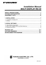
Replacement PartsALWAYS contact KVH Technical Support before youreplace a part (see page 37 for contact info).Part KVH Part #Antenna unit 02-1561Control unit 72-0367Modem 72-0365Ethernet switch 19-0536MTA 19-0504Remote service module 19-0490Gyro (A) 72-0294BUC cable (B) 72-0425Elevation motor belt (C) 72-0442LNB (D) 72-0364Elevation limit switch (E) 72-0299PCB (F) 72-0366GPS (G) 72-0298Azimuth limit switch (H) 72-0437Radome 72-0363Accessory KVH Part #UCH-250 fax server 19-0520Access controller 01-0327Crew calling system 72-034932 <strong>TracPhone</strong> <strong>V7</strong> Technician’s <strong>Pocket</strong> <strong>Guide</strong>
Replacement PartsEABCDFGH<strong>TracPhone</strong> <strong>V7</strong> Technician’s <strong>Pocket</strong> <strong>Guide</strong> 33
TP<strong>V7</strong> Flash Update WizardUse the TP<strong>V7</strong> Flash Update Wizard to upload newsoftware to the antenna.1. Download the Wizard from the KVH Partner Portal.2. Check for updates (viaInternet) to ensure theWizard contains thelatest software files.3. Turn off the modem;it must remain offduring flashing.Control Unit4. Connect your PCto the control unit’sMaintenance portthen turn on thecontrol unit.Maintenance PortMAINTENANCE PORTRS232Red (+42V)Black (Gnd)Not UsedWht/GryANTENNAGry/WhtWht/OrgOrg/WhtNot UsedWht/BrnBrn/WhtWht/BluBlu/WhtWire Colors:Body/StripeMODEMRS4225. Follow the Wizard’sonscreen instructions.34 <strong>TracPhone</strong> <strong>V7</strong> Technician’s <strong>Pocket</strong> <strong>Guide</strong>
Satellite Configuration FilesUpdated satellite configuration files are periodicallydownloaded to modems via the satellite. However, if amodem misses a download, you can manually update it.Contact KVH Technical Support before you updatea customer’s modem. Many customers have uniquecoverage needs that require a custom configuration.1. Download the latest files from the KVH Partner Portal.2. Connect your PC to the modem’s “User Enet” port (seepage 30) then turn on the modem and control unit.3. Enter http://192.168.0.1 into your web browser.4. At the Configuration tab, select the “Satellite” link. Atthe login, enter user admin and password arclight.5. Select “Browse” and select the new sed.csv.agt file.Then select “Upload.”6. Repeat step 5 to upload the new sscf.csv.agt file.7. Select “Save file(s).”8. When “File(s) saved” appears, select “Reboot.”<strong>TracPhone</strong> <strong>V7</strong> Technician’s <strong>Pocket</strong> <strong>Guide</strong> 35
Preventive MaintenanceCompleting the following tasks during a service call willhelp maintain peak performance.• Ensure that the system has the latest software versionsinstalled, and use the TP<strong>V7</strong> Flash Update Wizard toupdate them, if necessary (see page 34). The versionnumbers shown in the control unit’s Antenna Statusmenu should match the versions listed in the Wizard’sRelease Notes.• Clean the exterior of the antenna radome with freshwater; use a mild detergent to remove grime. Do notuse abrasive cleansers, and do not spray the antennawith high-pressure water.• Inspect the cable connections at the modem and controlunit. Repair any corroded connectors or frayed cables.• Using a vacuum, clean the vents on the rear and sideof the modem. Air needs to flow through these vents tocool the modem’s electronic components.Modem Vents36 <strong>TracPhone</strong> <strong>V7</strong> Technician’s <strong>Pocket</strong> <strong>Guide</strong>
TelephoneWithin Continental U.S.A.:1 866-701-7103 (via landline only)Technical SupportNorth/South America, Australia:+1 401-851-3806Europe, Middle East, Asia, Africa:+45 45 160 180E-mailNorth/South America, Australia:techs@kvh.comEurope, Middle East, Asia, Africa:support@kvh.dkKVH Partner Portal (dealers only)Portal web page: www.kvh.com/partnersCheck this site regularly for bulletins, application notes,manuals, price lists, training presentations, and more!<strong>TracPhone</strong> <strong>V7</strong> Technician’s <strong>Pocket</strong> <strong>Guide</strong> 37
AttributeSystem SpecsRatingReceive frequency 11.7-12.75 GHzTransmit frequency 14.0-14.5 GHzBUC output power 4 WElevation range 5°-80°Azimuth range 720° rotationWeightAntenna:60 lbs (27 kg)Control Unit & Modem:15 lbs (6.8 kg)Input powerTemperature,operatingHumidity Up to 95%Modem data outputCertificationSatellite coverageControl Unit & Antenna:90-240 VAC, 50-60 Hz, 2 A maxModem:90-240 VAC, 50-60 Hz, 3 A maxTotal system power: 500 W maxAntenna:-15°F to 130°F (-25°C to 55°C)Control Unit & Modem:32°F to 130°F (0°C to 55°C)Ethernet: IEEE 802.3, 10BASE-T/100BASE-TX, 100 Mbit/sComplies with specifications ofEMC Directive 1999/5/EC Radio& Telecommunications TerminalEquipment (R&TTE)See www.kvh.com/footprint38 <strong>TracPhone</strong> <strong>V7</strong> Technician’s <strong>Pocket</strong> <strong>Guide</strong>
NotesUse this space to jot down any additional technicalinformation you might need for future reference.<strong>TracPhone</strong> <strong>V7</strong> Technician’s <strong>Pocket</strong> <strong>Guide</strong> 39
© Copyright 2006 KVH Industries Inc.KVH and TracVision are registered trademarks ofKVH Industries Inc.www.kvh.com/partnersKVH Industries, Inc.50 Enterprise Center Middletown, RI 02842-5279 USAPhone: +1 401 847-3327 Fax: +1 401 849-0045E-mail: info@kvh.comKVH Europe A/SKokkedal Industripark 2B 2980 Kokkedal DenmarkPhone: +45 45 160 180 Fax: +45 45 160 181E-mail: info@kvh.dkInternet: www.kvh.com©2008-2010 KVH Industries, Inc., All rights reserved. U.S. Patent Pending.KVH and <strong>TracPhone</strong> are registered trademarks of KVH Industries, Inc.mini-VSAT Broadband is a service mark of KVH Industries, Inc.The information in this document is subject to change without notice.No company shall be liable for errors contained herein. (54-0486 Rev. G)