
You also want an ePaper? Increase the reach of your titles
YUMPU automatically turns print PDFs into web optimized ePapers that Google loves.
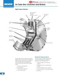
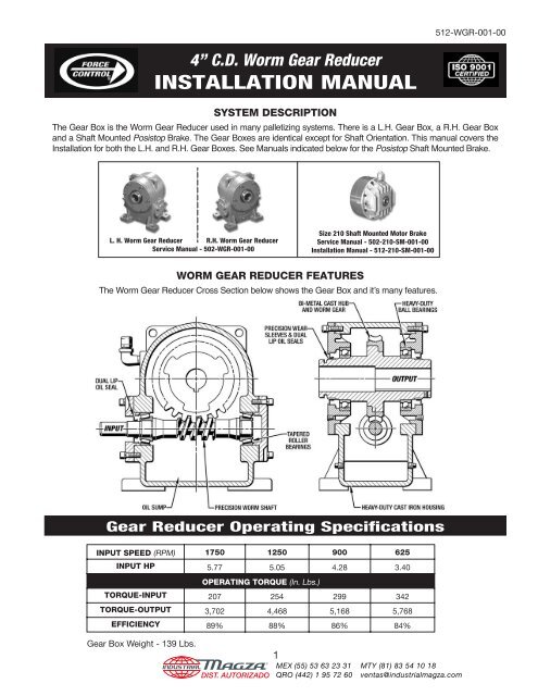
512-WGR-001-004” C.D. <strong>Worm</strong> <strong>Gear</strong> ReducerINSTALLATION MANUALSYSTEM DESCRIPTIONThe <strong>Gear</strong> <strong>Box</strong> is the <strong>Worm</strong> <strong>Gear</strong> Reducer used in many palletizing systems. There is a L.H. <strong>Gear</strong> <strong>Box</strong>, a R.H. <strong>Gear</strong> <strong>Box</strong>and a Shaft Mounted Posistop Brake. The <strong>Gear</strong> <strong>Box</strong>es are identical except for Shaft Orientation. This manual covers the<strong>Installation</strong> for both the L.H. and R.H. <strong>Gear</strong> <strong>Box</strong>es. See <strong>Manu</strong>als indicated below for the Posistop Shaft Mounted Brake.L. H. <strong>Worm</strong> <strong>Gear</strong> Reducer R.H. <strong>Worm</strong> <strong>Gear</strong> ReducerService <strong>Manu</strong>al - 502-WGR-001-00Size 210 Shaft Mounted Motor BrakeService <strong>Manu</strong>al - 502-210-SM-001-00<strong>Installation</strong> <strong>Manu</strong>al - 512-210-SM-001-00WORM GEAR REDUCER FEATURESThe <strong>Worm</strong> <strong>Gear</strong> Reducer Cross Section below shows the <strong>Gear</strong> <strong>Box</strong> and itʼs many features.<strong>Gear</strong> Reducer Operating SpecificationsINPUT SPEED (RPM) 1750 1250 900 625INPUT HP 5.77 5.05 4.28 3.40OPERATING TORQUE (In. Lbs.)TORQUE-INPUT 207 254 299 342TORQUE-OUTPUT 3,702 4,468 5,168 5,768EFFICIENCY 89% 88% 86% 84%<strong>Gear</strong> <strong>Box</strong> Weight - 139 Lbs.DIST. AUTORIZADO®1MEX (55) 53 63 23 31QRO (442) 1 95 72 60MTY (81) 83 54 10 18ventas@industrialmagza.com
<strong>Gear</strong> Reducer DimensionsDimensions are subject to change withoutnotice. Certified <strong>Installation</strong> Drawings areavailable upon request.Important Safety PrecautionsWARNING: THE GEAR REDUCER UNIT DESCRIBED IN THIS MANUAL MUST NOT BE INSTALLED IN ANYMANNER EXCEPT AS SPECIFIED HEREIN, AND MUST NOT BE OPERATED AT SPEEDS, TORQUE LOADS,OR TEMPERATURES OTHER THAN THOSE SPECIFIED IN THIS MANUAL. FAILURE TO LIMIT OPERATIONSOF THE GEAR REDUCER TO THE CONDITIONS SPECIFIED COULD DAMAGE THE UNIT, WILL VOID ANYWARRANTIES, AND MAY CAUSE MALFUNCTIONS OR DAMAGE TO INTERCONNECTING EQUIPMENT.CAUTION: BEFORE PERFORMING ANY WORK ON THE GEAR BOX, TAKE THE FOLLOWINGSAFETY PRECAUTIONS.A. INITIAL PROCEDURETHIS SECTION ONLY PERTAINS TO PALLETIZER SYSTEMS.1. Lower the main hoist to the down position.2. After the main hoist has been safely positioned, themachine must be made safe to enter.Push one of the Emergency Stop buttons located at thefollowing: A. Main Electrical Panel, B. Main Hoist Frame,C. Pallet Magazine Remote, D. Remote Control Panel ontop of the palletizer.CAUTION: DO NOT ENTER THE MACHINE YET.If maintenance must be performed on the machine, themain power must be locked out at the main electricalcontrol panel.CAUTION: THE HOIST MUST BE IN THEDOWN POSITION.B. MAIN PANEL LOCKOUT PROCEDURETurn the Main Power Disconnect switch to the OFF positionat the Main Electrical Control Panel.Insert a lock into the switch, and place an identifier tag2DIST. AUTORIZADO®at the lock to indicate the machine is being worked on byyou and why.NEVER REMOVE A LOCKOUT UNLESS YOUHAVE PERMISSION TO.Now try to operate some of the controls. The machineshould not operate. If the machine will operate call aqualified maintenance technician.REMEMBER TO “LOCKOUT & TRY OUT”If the palletizer will not operate it is safe to enter the machine.3. <strong>Manu</strong>ally release the existing brake. The main hoistshould move downward slightly and come to rest onthe lower frame of the palletizer. If not, reset the brakeand install cribbing to support the main hoist to preventit from moving down.4. The drive shaft connecting the motor and reducer highspeed shafts must be removed to access the brake.Match mark the drive shaft couplings so that machinetiming can be restored when the brake installation iscomplete. Remove the drive shaft and set aside.MEX (55) 53 63 23 31QRO (442) 1 95 72 60MTY (81) 83 54 10 18ventas@industrialmagza.com
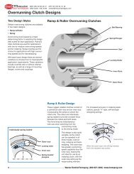
<strong>Gear</strong> Reducer <strong>Installation</strong>A. RECEIVING THE WORM GEAR REDUCER1. Remove the red plastic pipe plug in the side of the<strong>Gear</strong> Reducer Housing and install the Street Elbow(#836) and the Air Breather (#832).WARNING: Failure to install the Air Breather(#832) properly could cause damage tothe unit and void the Warranty.2. Check the fluid level as indicated in Lubrication onpage 4. Add fluid if necessary.B. MOUNTING THE WORM GEAR REDUCER(See Figure Below)Use 1/2”-13 SAE Grade 5 Hex Hd. Mounting Bolts andLockwashers.Make sure the mounting surface is thoroughly cleanedand free of any burrs or surface defects that would causemisalignment.1. Check the fit for the Thru-Shaft by sliding the Thru-Shaft back and forth through the hub bore to makesure that it is a smooth slip-fit.Check the fit of the Thru-Shaft with the Key installed.Make sure that there is no binding around the keyway.NOTE - Use Never-Seeze or a good synthetichigh temperature grease on the shaft and key.2. Install the <strong>Gear</strong> Reducer on the machine. Only handtighten the mounting bolts at this time.3. Install the Thru-Shaft and tighten the Pillow BlockBearings.4. Align the Input Shaft to the Power Source. Use an adequatenon backlash coupling. Make sure the Axial,Parallel and Angular Alignment is correct as per theCouplings <strong>Manu</strong>facturersʼ Alignment Specifications.5. Shim under the motor as needed to assure correctalignment.NOTE - If the Thru-Shaft determines the verticalposition of the gear box, you may also have toshim under the gear box feet to accommodatefor any vertical space to the mounting surface.6. Tighten down mounting bolts. Torque to 60 Lb. Ft.7. After the <strong>Worm</strong> <strong>Gear</strong> Reducer has been in operationfor a few hours, make sure the mounting bolts aretight and re-check alignment.8. After the <strong>Worm</strong> <strong>Gear</strong> Reducer has been in operationfor 40 hours, make sure the mounting bolts are stilltight. Tighten if necessary.GEAR REDUCER INSTALLATIONDIST. AUTORIZADO®3MEX (55) 53 63 23 31QRO (442) 1 95 72 60MTY (81) 83 54 10 18ventas@industrialmagza.com
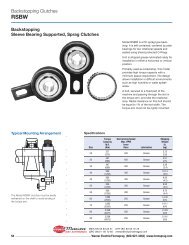
<strong>Gear</strong> Reducer LubricationA. CHECKING THE OIL LEVELCheck the oil level when the drive is installed and weeklythereafter (until experience dictates otherwise). Alwayscheck the oil level with the unit stationary (not running).The oil level should be at the bottom of the pipe plughole. NOTE - The Oil Level Pipe Plugs (#835) are onboth sides so the oil level is visible from either side. See<strong>Gear</strong> Reducer Lubrication Figure.B. CHANGING THE OILOil in the <strong>Worm</strong> <strong>Gear</strong> Reducer should be changed everytwelve (12) months. More frequent oil change maybe required for high kinetic energy applications or inextremely dirty environments.C. TYPE OF OILUse Mobilgear 634 or 600W Cylinder Oil ONLY (Unlessotherwise specified on the unit nameplate).GEAR REDUCER LUBRICATIONRemove the Drain Plug (#834) at the bottom of themain housing. Drain all oil before refilling. Replace thedrain plugs. Remove Breather (#832) and Oil Level Plug(#835). Refill unit with clean oil until oil comes up tothe oil level hole and replace Pipe Plug (#835) and theBreather (#832).WARNING: Failure to install the Air Breather(#832) properly could cause damage tothe unit and void the Warranty.CAUTION: Do not over-fill. Excess oil willcause the unit to overheat.A. FACTORY REBUILD SERVICEFactory Rebuild ServiceMaintenance and Service <strong>Manu</strong>alsA Factory Re-Build Service is offered by Force ControlIndustries, Inc. Contact our service and sales departmentat Force Control for additional information.B. MAINTENANCE AND SERVICE MANUALSA complete Service <strong>Manu</strong>al can be downloaded andprinted off of our web site or ordered directly from ForceControl. It is as follows:Service <strong>Manu</strong>al and Repair Parts for the 4” C.D. <strong>Worm</strong><strong>Gear</strong> Reducer is 502-WGR-001-00Go to: www.forcecontrol.comAll of our Catalogs and Service <strong>Manu</strong>als on the web siteare in PDF format and will require Adobe Acrobat Reader5.0 or later to open them. This Adobe Acrobat Readercan be downloaded from our web site if you do not haveit installed on your computer.FORCE CONTROL INDUSTRIES, INC.3660 Dixie HighwayFairfield, Ohio 45014Phone: 513-868-0900Fax: 513-868-2105E-Mail: info@forcecontrol.comWeb Site: www.forcecontrol.com4DIST. AUTORIZADO®MEX (55) 53 63 23 31QRO (442) 1 95 72 60MTY (81) 83 54 10 18ventas@industrialmagza.com