
You also want an ePaper? Increase the reach of your titles
YUMPU automatically turns print PDFs into web optimized ePapers that Google loves.
DIST. AUTORIZADO®MEX (55) 53 63 23 31QRO (442) 1 95 72 60MTY (81) 83 54 10 18ventas@industrialmagza.comBoston Gear ®RB SeriesDC Motor Speed ControlInstallation and OperationDoc. No. <strong>19025</strong>RB1, B, S, RRB2, B, S, RRB3, B, Rwww.bostongear.com
TABLE OF CONTENTSDIST. AUTORIZADO®MEX (55) 53 63 23 31QRO (442) 1 95 72 60MTY (81) 83 54 10 18ventas@industrialmagza.comGENERAL INFORMATIONPAGEDescription 4Enclosure 4Ratings 4Operating Conditions 5Performance Characteristics 5Installation and Wiring 8Startup and Operation 13Maintenance 14MODIFICATIONSFull Wave Field 14Half Voltage Output 15Increased Acceleration Time 15Limit Switch Reversing 16Torque Control 18Tachometer Feedback 20Line Starting 21TROUBLESHOOTING 24PARTS LISTTABLE1 Ratiotrol <strong>Beta</strong> Model Matrix 42 Operator Controls 53 Ratings 54 Speed Regulation Characteristics 65 Dynamic Braking Characteristics 76 Calibration Wires 97 Full Wave Field 148 Capacitor Values/Acceleration 159 Contactor Selection 2310 Troubleshooting 242 Doc. No. <strong>19025</strong> • Boston Gear ® Ratiotrol ® DC Motor Speed Control
TABLE OF CONTENTSDIST. AUTORIZADO®MEX (55) 53 63 23 31QRO (442) 1 95 72 60MTY (81) 83 54 10 18ventas@industrialmagza.comFIGURE1 Typical <strong>Beta</strong> Enclosed Controller 72 Series <strong>Beta</strong> Mounting Configurations 83 Main Board Connections 94 Internal View <strong>Beta</strong> Controller 105 AC Power and Motor Connections 116 Connections Models RB! and RB2 127 Connections Models RB3 and RB3B 128 Full Wave Field 149 Increased Acceleration Time 1610 Limit Switch Reversing 1711 Limit Switch Reversing Using RCS6 Remote Control Station 1712 Torque Control with Torque Pot Only 1913 Torque Control with Torque Pot and Run Speed Pot 1914 Tachometer Feedback for 7 VDC/1000 RPM Generator 2015 Tachometer Feedback for 35-50 VDC/1000 RPM Generator 2016 Moving Capacitor C18 for Line Start Operation 2117 Recommended Customer Connection Diagram for Line Start Operation 2318 RB1, RB2, RB3 Mounting Dimensions 2319 RB1, RB2, RB3 (Types B, S, R) Mounting Dimensions 23SCHEMATICSRun-Stop 26Switch Reverse 27Magnetic Reverse 28Doc. No. <strong>19025</strong> • Boston Gear ® Ratiotrol ® DC Motor Speed Control 3
GENERAL INFORMATIONDIST. AUTORIZADO®MEX (55) 53 63 23 31QRO (442) 1 95 72 60MTY (81) 83 54 10 18ventas@industrialmagza.comDescriptionRatiotrol <strong>Beta</strong> controllers statically convert single-phase AC line power to regulated DC foradjustable-speed armature control of shunt-wound and permanent-magnet motors. The controllersare Underwriters Laboratories Listed. (File No. 71E60208)EnclosureTotally enclosed, non-ventilated, constructed of rugged die-cast aluminum alloy. Gasketed,screw fixed cover excludes contaminants. Provision for conduit entry is included top and bottomby two (2) 3/4-14 NPT tapped holes. Standard unit is easily and inexpensively convertibleto NEMA Type 3, 4 or 12.Model TypesTable 1. Ratiotrol <strong>Beta</strong> Model MatrixFunction Configuration OperatorControlsModelUnidirectionalRun-StopArmature SwitchReversingArmature ContactorReversing and D.B.Open ChassisEnclosedLocal (Integral)Remote (*)Power SourceAndHorsepowerRange115VAC50/60 Hz230VAC50/60 HzRB1 X X XRB1B X X X 1/12 - 1HP N/ARB1S X X XRB1R X X XRB2 X X XRB2B X X XRB2S X X XReconnectableUnits115VAC50/60 Hz230VAC50/60 HzRB2R X X XRB3 X X X 1/12 - 1HP 1/2 - 2HPRB3B X X XRB3R X X X* Operator controls provided by user4 Doc. No. <strong>19025</strong> • Boston Gear ® Ratiotrol ® DC Motor Speed Control
OPERATOR CONTROLSTable 2. Operator ControlsDIST. AUTORIZADO®MEX (55) 53 63 23 31QRO (442) 1 95 72 60MTY (81) 83 54 10 18ventas@industrialmagza.comControllerSuffixB or no SuffixNoneOperator ControlsS 1. Run/Stop Switch - 2 maintained positions2. Motor Speed Pot - 5K ohm, 1/2 wattRATINGS1. Run/Stop Switch - maintained positionsR 2. Fwd/Rev Switch - 3 maintained positions with center detent(RB1, 2)position for antiplug protection3. Motor Speed Pot - 5K ohm, 1/2 watt1. Run/Stop Switch - 2 maintained positionsR 2. Rwd/Rev Switch - 2 momentary positions with return(RB3 only)to center3. Motor Speed Pot - 5K ohm, 1/2 watt1. Service Factor . . . . . . . . . . . . . . . . . . . . . . . . . . . . . . . . . . . . . . . . . . . . . . . . . . . . . . . . . . . . . . . . . . . . . . . . . .1.02. Duty . . . . . . . . . . . . . . . . . . . . . . . . . . . . . . . . . . . . . . . . . . . . . . . . . . . . . . . . . . . . . . . . . . . . . . . . . . .Continuous3. Overload Capacity . . . . . . . . . . . . . . . . . . . . . . . . . . . . . . . . . . . . . . . . . . . . . . . . . . . . . . . . . . .150% for 1 minute4. AC Line Fuse Interrupting Capacity . . . . . . . . . . . . . . . . . . . . . . . . . . . . . . . . . . . . . . . . . . . . . . . .5000 amperesTable 3. RatingsComponent1-Phase115VAC50 or 60 Hz Line UnitAC Input Amps 230VAC(Full Load)Rated Horsepower1/12 1/6 1/4 1/3 1/2 3/4 1 1 1/2 22.0 3.9 5.0 6.0 8.7 12.4 15.0 ---- ----Unit---- ---- ---- ---- 4.2 5.9 8.8 12.6 15.8KVA .30 .48 .58 .71 1.0 1.4 2.0 3.0 4.0Motor90V 0.9 2.0 2.8 3.5 5.4 8.1 10.5 ---- ----Armature180V ---- ---- ---- ---- 2.6 3.8 5.5 8.2 11.6DC Output Amps(Full Load) Motor50V ---- 1.0 1.0 1.0 1.0 1.0 1.0 ---- ----Field100V ---- ---- ---- ---- 1.0 1.0 1.0 1.0 1.0AmpsFull Load Torque (LB. FT.).25 0.5 0.75 1.0 1.5 2.2 3.0 4.5 6.0With 1750 RPM Base Speed MotorsRB1, RB2RB33.25 (1.48 kg)3.8 (1.73 kg)WeightRB1B, RB1SLBS. (kg) RB2B, RB2S 5.5 (2.5 kg)RB1R, RB2RRB3B, RB3R6.05 (2.75 kg)Doc. No. <strong>19025</strong> • Boston Gear ® Ratiotrol ® DC Motor Speed Control 5
OPERATING CONDITIONSDIST. AUTORIZADO®MEX (55) 53 63 23 31QRO (442) 1 95 72 60MTY (81) 83 54 10 18ventas@industrialmagza.com1. Line Voltage Variation . . . . . . . . . . . . . . . . . . . . . . . . . . . . . . . . . . . . . . . . . . . . . . .± 10% of rated2. Line Frequency Variation . . . . . . . . . . . . . . . . . . . . . . . . . . . . . . . . . . . . . . . . . . . . . . . . . . .± 2 Hz3. Ambient Temperature (*) . . . . . . . . . . . . . . . . . . . . . . . . . . . . . . . . . .0ºC to 40ºC (32ºF to 104ºF)4. Altitude (standard) . . . . . . . . . . . . . . . . . . . . . . . . . . . . . . . . .3300 feet (1000 meters) maximum* 55ºC (131ºF) maximum in enclosed areas where RB1, RB2 or RB3 open chassis units are mounted.PERFORMANCE CHARACTERISTICS1. Controlled Speed Range . . . . . . . . . . . . . . . . . . . . . . . . . . . . . . . . . . . . . .0 to motor base speed2. Speed Regulation (See Table 4) - Regulation percentages are of motor base speed understeady-state conditions3. Efficiency (at maximum speed)a. Controller . . . . . . . . . . . . . . . . . . . . . . . . . . . . . . . . . . . . . . . . . . . . . . . . . . . . . . . . . . . . .99%b. Controller with motor . . . . . . . . . . . . . . . . . . . . . . . . . . . . . . . . . . . . . . . . . . . . . . . . . . . .85%4. Displacement Power Factor (Rated Speed/Rated Load) . . . . . . . . . . . . . . . . . . . . . . . . . . . .87%5. Acceleration (non-adjustable) . . . . . . . . . . . . . . . . . . . . .By fixed ramp with current limit override6. Current Limit (non-adjustable) . . . . . . . . . . . . . . . . . . . . . . . . . . . .150% full-load torque (typical)Table 4. Speed Regulation CharacteristicsVariableLoad Line Field Temperature SpeedRegulation Method Change Voltage Heating (1) ± 10ºC Range95% ± 10% Cold/NormalStandard VoltageFeedback with IR 2% ± 1% 5-12% ± 2% 50:1CompensationOptional Speed (Tach) 0.5% ± 1% 0.2% ± 2% 100:1Feedback (2)(1) Does not apply to Permanent-Magnet Motors(2) Unidirectional Models Only6 Doc. No. <strong>19025</strong> • Boston Gear ® Ratiotrol ® DC Motor Speed Control
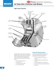
PERFORMANCE CHARACTERISTICS (Con’t)DIST. AUTORIZADO®MEX (55) 53 63 23 31QRO (442) 1 95 72 60MTY (81) 83 54 10 18ventas@industrialmagza.comFigure 1. Typical <strong>Beta</strong> Enclosed Controller7. Dynamic Braking - Supplied in Models RB3, RB3B and RB3R. Provides initial braking torque andstops per minute as shown in Table5. The dynamic braking resistor is rated for stopping a typicalload when the motor load inertia does not exceed the motor armature inertia.HIGHER INERTIA LOADS AND/OR ARMATURE VOLTAGE HIGHER THAN RATED MAYEXTEND BRAKING TIME BEYOND THE WATTAGE RATING OF THE DYNAMIC BRAKINGRESISTOR.Table 5. Dynamic Braking CharacteristicsComponentBraking Torque %Stops Per MinuteUnitRated Horsepower1/12 1/6 1/4 1/3 1/2 3/4 1 1-1/2 2115V 200 180 129 103 66 44 34 --- ---230V --- --- --- --- 278 190 130 88 62115V 20 15 12 11 8 6 2 --- ---230V --- --- --- --- 8 6 1 1 1Doc. No. <strong>19025</strong> • Boston Gear ® Ratiotrol ® DC Motor Speed Control 7
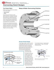
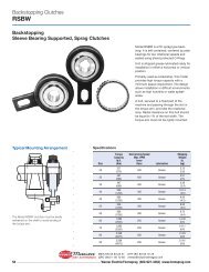
INSTALLATION AND WIRINGDIST. AUTORIZADO®MEX (55) 53 63 23 31QRO (442) 1 95 72 60MTY (81) 83 54 10 18ventas@industrialmagza.comBE SURE TO READ ALL THE FOLLOWING INSTALLATION AND WIRING INSTRUCTIONSBEFORE INSTALLING THE CONTROLLER.1. Unpack the controller.2. Remove the controller front cover (if applicable) and check components in the controller. Reportshipping damage to the carrier.Figure 2. Series <strong>Beta</strong> Mounting Configurations3. The controller can be mounted in any of four configurations, as shown in Figure 2.4. Conduit entry is made by driving a 5/8” diameter pipe nipple, socket or similar rigid objectthrough the conduit opening. On all models install a 3/4” x 14 conduit fitting or pipe.NOTE: DO NOT USE A PUNCH SINCE THIS WILL LEAVE SHARP PROTRUSIONS AROUNDTHE OPENING. To prevent component damage from knockout fragments, apply masking tape tothe inside of the knockout before removing it.5. Remove the proper calibration wire(s) from the controller main board with a wire cutter, as shownin Table 6 and Figure 3.6. Be sure the main board is connected for the correct voltage. Figure 3 shows the main board connectedfor 230 volt operation. For 115 volt operation, the yellow and white leads on TransformerT1 connect to the 115V tabs, and the feedback jumper connects to the 90V ARM tab.NOTE: Model RB1 Controllers are designed for 115 volt operation only.7. Replace the front cover (if applicable) on the chassis.8. Mount the controller. If the controller is subjected to vibrations, it must be shock mounted.NOTE: Never mount the controller immediately beside or above the heat-generating equipment,or directly below water or steam pipes. If the controller is mounted in an enclosure, be sure thetemperature in the enclosure does not exceed 550.9. Prepare for wiring by removing the front cover (if applicable) and attaching it to the chassis asshown in Figure 4.8 Doc. No. <strong>19025</strong> • Boston Gear ® Ratiotrol ® DC Motor Speed Control
INSTALLATION AND WIRING (Con’t)DIST. AUTORIZADO®MEX (55) 53 63 23 31QRO (442) 1 95 72 60MTY (81) 83 54 10 18ventas@industrialmagza.comMotor Horsepower90 VDC 180 VDCRemove Wires1/12 1/6 R9 Thru R141/8 1/4 R9 Thru R141/6 1/3 R9 Thru R141/4 1/2 R10 Thru R141/3 3/4 R10 Thru R141/2 1 R11 Thru R143/4 1 1/2 R13 Thru R141 2 NoneTable 6. Series Calibration WiresCalibrationWiresT1YellowR8R9R10R11R12R13R14Figure 3. Main Board ConnectionsYellow115 V TabsTB1 A+ A- F- F+ L1 L2Fdbk JumperOn 180V ArmFdbk TabWhiteYellow230V180V 90VWhiteT1 Leads On230 V Tabs90V ArmFdbk TabDoc. No. <strong>19025</strong> • Boston Gear ® Ratiotrol ® DC Motor Speed Control 9
INSTALLATION AND WIRING (Con’t)DIST. AUTORIZADO®MEX (55) 53 63 23 31QRO (442) 1 95 72 60MTY (81) 83 54 10 18ventas@industrialmagza.comFigure 4. Internal View <strong>Beta</strong> ControllerCAUTIONa. SEPARATE OVERCURRENT PROTECTION IS REQUIRED BY THE NATIONAL ELECTRICALCODE. THE USER IS RESPONSIBLE FOR CONFORMING WITH THE NATIONAL ELECTRI-CAL CODE AND ALL APPLICABLE LOCAL CODES WHICH GOVERN SUCH PRACTICES ASWIRING PROTECTION, GROUNDING DISCONNECTS AND OTHER PROTECTION.b. THE AVAILABLE SHORT-CIRCUIT CURRENT OF THE INPUT SUPPLY MUST BE LESS THAN5,000 AMPERES SYMMETRICAL OR CONTROLLER DAMAGE MAY RESULT. Short circuit currentcan be limited by sizing the input supply transformer at 50KVA or less, or by using correctlysized current limiting fuses in the input supply to the controller.c. NEVER USE POWER FACTOR CORRECTION CAPACITORS ON THE INPUT LINE TO THECONTROLLER. These capacitors can damage the solid-state components.10 Doc. No. <strong>19025</strong> • Boston Gear ® Ratiotrol ® DC Motor Speed Control
INSTALLATION AND WIRING (Con’t)DIST. AUTORIZADO®MEX (55) 53 63 23 31QRO (442) 1 95 72 60MTY (81) 83 54 10 18ventas@industrialmagza.com10. Use #14AWG stranded wire and connect the line and motor wiring to Terminal Strip TB1 asshown in Figure 5. Route the wiring as shown in Figure 4.TB1AC PowerMotorShuntField{*L2L1F+F-A-A+Motor ArmFigure 5. AC Power And Motor ConnectionsNOTE: Connections shown in Figure 5 do not provide positive disconnect of power from the motoron Models RB1 and RB2. Model RB1 should only be connected to 115VAC power. ModelsRB2 and RB3 are shipped for connection to 230VAC power, but they are reconnectable for115VAC power per Figure.11. Connect ground to a controller mounting screw. Be sure to remove the paint where the groundscrew contacts the controller.12. Do not close the controller until “startup” is complete.Models RB1, RB1B, RB2, RB2R, RB3 And RB3B13. Use Alpha No. 1898 or equal twisted cable and connect the operator controls to the controlleras shown in Figure 6 or 7. Maintain separation between the power wiring (Figure 5) and theoperator control wiring by 2” minimum.Doc. No. <strong>19025</strong> • Boston Gear ® Ratiotrol ® DC Motor Speed Control 11
DIST. AUTORIZADOMODELS RB1, RB1B, RB2, RB2R, RB3 AND RB3B (Con’t)®MEX (55) 53 63 23 31QRO (442) 1 95 72 60MTY (81) 83 54 10 18ventas@industrialmagza.comMotor Speed Pot100 05K 1/2WRunContactTB28765432NOTES:1. Contacts and motor speed pot areuser supplied.2. Contacts must be rated at 4 ma DCminimum3. Symbol “ “ means twisted wire.1Figure 6. Connections Models RB1 & RB2GndMotorSpeed5K, 1/2W1000Run FwdRun RevStopTB11234567891012357910312TB287654321123456TB397510PushbuttonPanetRemoteStationFigure 7. Connections Models RB3 & RB3B12 Doc. No. <strong>19025</strong> • Boston Gear ® Ratiotrol ® DC Motor Speed Control
DIST. AUTORIZADOMODELS RB1, RB1B, RB2, RB2R, RB3 AND RB3B (Con’t)®MEX (55) 53 63 23 31QRO (442) 1 95 72 60MTY (81) 83 54 10 18ventas@industrialmagza.comStartup And Operation1. Be sure all operator switches are in STOP or in neutral center position.2. Turn the MOTOR SPEED control pot to zero on its dial.3. Apply AC power to the controller.Models RB1, RB2, RB1B And RB2B4. Close the run contact between Terminals 3 and 4.5. Turn the MOTOR SPEED control pot until the motor rotates.Models RB3 And RB3B4. Push the RUN FWD button.5. Turn the MOTOR SPEED control pot until the motor rotates.6. Reverse Operation - Push the STOP button and then push the RUN / REV button. The motorwill dynamically brake to a stop and then accelerate in the opposite direction. Do not exceedthe braking capabilities listed in Table 5, page 7.Models RB1S And RB2S4. Place the RUN/STOP switch in RUN position.5. Turn the MOTOR SPEED pot until the motor rotates.Models RB1R And RB2R4. Place the RUN/STOP switch in RUN position.5. Place the FWD/REV switch in FWD position.6. Turn the MOTOR SPEED pot until the motor rotates.7. Reverse Operation - Place the FWD/REV switch in REV position. If the motor load inertiaexceeds the motor inertia, place the RUN/STOP switch in STOP position before changing theFWD/REV switch.Model RB3R4. Place the RUN/STOP switch in RUN position.5. Push the FWD/REV switch into FWD position. This position is momentary. When the switch isreleased, it returns to the center position.6. Turn the MOTOR SPEED pot until the motor rotates.7. Reverse Operation - Place the RUN/STOP switch in STOP position and then return it to RUNposition. Next, push the FWD/REV switch into REV position. This position is momentary. Whenthe switch is released, it returns to the center position. The motor will dynamically brake to astop and then accelerate in the opposite direction. Do not exceed the braking capabilities listedin Table 5.Notes:1. If motor rotation is opposite to that desired, stop the motor, turn-off the AC supply, andinterchange the motor armature leads.2. Turn the MOTOR SPEED pot to zero on its dial and check minimum speed, which isnormally set for zero. To readjust minimum speed, turn the MIN SPD pot on the mainboard. See Figure 4.3. The MOTOR SPEED pot controls forward, reverse and jog speeds from minimum speedto maximum speed.4. Whenever the AC input power is interrupted (turned-off), the controller must be reset after theAC power is restored by initiating a Stop function and then a Run function.This feature prevents accidental restarts.Doc. No. <strong>19025</strong> • Boston Gear ® Ratiotrol ® DC Motor Speed Control 13
MAINTENANCEDIST. AUTORIZADO®MEX (55) 53 63 23 31QRO (442) 1 95 72 60MTY (81) 83 54 10 18ventas@industrialmagza.comMaintenance consists of keeping the controller clean and dry. Refer to maintenance instructionssupplied by the motor manufacturer. If the motor does rotate, check the fuse on top of thecontroller. The fuse type is shown on the controller data label.CAUTIONSUBSTITUTE FUSES CAN CAUSE CONTROLLER DAMAGE.WARNINGBE SURE THE AC INPUT POWER IS REMOVED BEFORE WORKING ON THECONTROLLER. High voltage within the controller can cause electric shockresulting in personal injury or loss of life.<strong>Beta</strong> ModificationsFull Wave FieldTable 7.The standard half wave field supply may be converted to a full wave field supply. This modificationdoubles the field voltage that would otherwise be available. The table below shows therelationship.Standard Half Wave Full Wave Field VoltageAC Line Volts Field Voltage After Modification115 VAC 50 VDC 100 VDC230 VAC 100 VDC 200 VDCIn order to obtain the increased filed voltage, two diodes must be installed in the PC board.These diodes together with the two diodes in the power bridge form a full wave rectifier circuit.Figure 8 shows the location of the diodes. Observe the orientation of the band marking on thedevices when installing them. Use IN5399 diodes or similar 1.5A, 1000V diodes. Remove theexisting jumper as shown in Figure 8 and install #20 insulated wire between the holes connectedby the dotted line.Install Two Diodes(Note orientation ofband on diode)R8R9R10R11D17Main BoardD16R12R13 HighR14VoltageField OptionE4 E5 E6 E7BlkYelTB1Install and solder wirebetween holes connectedby dotted line.A+ A- F- F+ L1Figure 8. Full Wave FieldUnsolder wire fromPC board.14 Doc. No. <strong>19025</strong> • Boston Gear ® Ratiotrol ® DC Motor Speed Control
HALF VOLTAGE OUTPUTDIST. AUTORIZADO®MEX (55) 53 63 23 31QRO (442) 1 95 72 60MTY (81) 83 54 10 18ventas@industrialmagza.comWhen the <strong>Beta</strong> controller is calibrated for 230 VAC, the armature voltage is adjustable from 0to 180 VDC. It is possible to reduce this range to 0 to 90 VDC by moving the feedback jumperon the main board from its 180V position to the 90V position. This effectively doubles the armaturefeedback signal to the controller’s error amplifier, thus reducing the armature voltage byhalf. Although the armature voltage is reduced, the field voltage remains at 100 VDC.Furthermore, the controller must now be calibrated for horsepower as if it were a 115 VAC unit.Because the armature voltage is reduced by half, the gain of the system has doubled. Thismay cause instability at certain loads or speeds. Another consideration is the controller/motorform factor. The form factor is much higher when obtaining 90 VDC from a 230 VAC controllerthan it would be if the 90 VDC were obtained from 115 VAC. This will increase motor heating tosome extent and may cause commutation difficulties. Therefore, the suitability of this mode ofoperation should be confirmed by testing or consulting the motor manufacturer.INCREASED ACCELERATION TIMEThe time it takes the <strong>Beta</strong> controller to bring the motor to full speed may be increased from thestandard 0.3 second time to a maximum of 2.5 minutes. This is done by installing a 25V, axiallead electrolytic capacitor on the PC board. The value of the capacitor in microfarads determinesthe time the motor will take to reach full speed. The following table shows standard valuesof capacitors and the acceleration time obtained with each. The time listed is approximatedue to the tolerance of the capacitor and is specified at the point the armature voltage reaches95% of its final value. Although values larger than 1000 MFD may be used, it is not recommended.Larger values may prohibit the controller from reaching full speed.Table 8. Capacitor Values/AccelerationCapacitance (MFD) Time (SEC.)30 550 8100 15150 23200* 301000* 2.5 min.*These caps may not fit into the space provided on the PCboard. In this case the caps leads may be insulated and bent sothat they reach the holes provided.Capacitor values for other acceleration times may be obtained by using the following formula:(6.66 x Time) -2 is approximate equal to capacitance in MFDSelect a standard capacitor value which is close to the calculated result.Example:Compute the value of capacitance required for an acceleration time of two seconds:(6.66 x 2) -2 = 11.3 MicrofaradsTherefore, a 10 MFD capacitor would be installed on the <strong>Beta</strong> controller’s main board.Doc. No. <strong>19025</strong> • Boston Gear ® Ratiotrol ® DC Motor Speed Control 15
INCREASED ACCELERATION TIME (Con’t)DIST. AUTORIZADO®MEX (55) 53 63 23 31QRO (442) 1 95 72 60MTY (81) 83 54 10 18ventas@industrialmagza.comFigure 9 shows the location of the acceleration capacitor. Observe the polarity when installingit.Main BoardR1C2C3C5C19Accel CapOption2R19180V 90VArmTach1 2Install Capacitor here(Note Positive Polarity)Figure 9.LIMIT SWITCH REVERSINGLimit switch reversing controls the direction of motor rotation by the use of limit switches. Theprocess starts by pressing a forward or reverse pushbutton. Typically the motor runs one directionperforming a process until the machine encounters a limit switch. The switch then causesthe motor to reverse direction. Finally, the limit switch at the beginning of the process is activated,reversing the motor direction again. This action continues until a stop button is pressed.The RB3 controller is the only model controller capable of performing this function. In fact, noadditional electronics are required when using the RB3 controller. It can be mounted in anexisting enclosure or a blank cover can be added, enclosing the controller for convenientmounting.The “R” cover cannot be used for this application. Either an RCS6 remote station (Figure 11) ora custom station, with the controls shown in Figure 11, is required.A jumper wire (J1) on the RB3 magnetic reversing board must be cut to break the on-boardconnection between TB3 terminals 5 and 6 in order to use limit switch reversing. This is shownin Figure 10.16 Doc. No. <strong>19025</strong> • Boston Gear ® Ratiotrol ® DC Motor Speed Control
LIMIT SWITCH REVERSING (Con’t)DIST. AUTORIZADO®MEX (55) 53 63 23 31QRO (442) 1 95 72 60MTY (81) 83 54 10 18ventas@industrialmagza.comC7C6C2R10R2338R22J127123C3TB34 5 6Magnetic Reversing Bd67470 1045893___ RevCut JumperFigure 10. Location of J1 JumperRevTB391H1 To Run7 8Fwd LimitFwdSwitch(1) 5StopRev9 10Fwd Limit SW. (1)6Limit SW.Rev Limit SW.2+48V37MR45MF1056MF Cut JumperMR1045893 Rev. DMagnetic Reversing BoardRunSpeed10001/2W5K213TB2568Main Board1045892Figure 11. Limit switch Reversing Using RCS6 Remote Control StationNOTES:1. Wires connected to TB2 and TB3 must be twisted cable - such as Alpha 1893/3.2. Symbol “ “ are terminals located on RCS6 remote control station.Doc. No. <strong>19025</strong> • Boston Gear ® Ratiotrol ® DC Motor Speed Control 17
TORQUE CONTROLDIST. AUTORIZADO®MEX (55) 53 63 23 31QRO (442) 1 95 72 60MTY (81) 83 54 10 18ventas@industrialmagza.comThe standard mode of operation of the <strong>Beta</strong> controller is that of a speed controller with currentlimit. This means that the controller will regulate speed until the current reaches 100-120% ofthe motor’s rated armature current. As the load increases beyond 120%, the controller’s voltagewill reduce until the motor has stopped rotating at 15% of rated current. Because the controlleris regulating speed, the current or torque of the motor is allowed to vary up to 100% asrequired by the mechanical load.Some applications require the opposite mode of operation. The controller in this case controlsthe torque of the motor, allowing the speed to vary between zero RPM and base speed.Actually, the speed of the torque controlled motor is set by the speed of the material or systemthe torque controlled motor is pulling against.For Example:A torque controller is used to power a motor connected to a spool winding up scrap metal. Themetal is being extruded from the process at a given rate. If a speed controller were used, thespeed of the winder would have to match the speed of the material; otherwise, the materialwould go slack or become taut. It would be expensive and undesirably complicated to try tomatch the speed. However, with torque control, the process speed can vary and the controllerwill continue to regulate torque, disregarding any process speed changes. Because the materialis always in tension, the speed of the torque motor will necessarily have to be proportional tothe process speed. But, what happens when the material breaks:”If the torque controlled motor doesn’t have a process to exert its torque against, the motor willrun at maximum speed. This should be taken into consideration when planning the installation.Make sure that the appropriate safety precautions are taken in the event of a material breakage,causing the winder to run at maximum speed.In order to use the torque control mode of operation either a 5K, 1/2W pot is required or an “S”or “R” cover assembly. The speed pot in these cover assemblies can easily be converted to atorque pot by moving the wire on TB2-5 to TB2-7, then cut the jumper as shown in Figure 12.A #20 AWL insulated jumper is also required between TB2-6 and TB2-5.18 Doc. No. <strong>19025</strong> • Boston Gear ® Ratiotrol ® DC Motor Speed Control
TORQUE CONTROL (Con’t)DIST. AUTORIZADO®MEX (55) 53 63 23 31QRO (442) 1 95 72 60MTY (81) 83 54 10 18ventas@industrialmagza.comMain Bd 1045892R43D33C12R27R29R24D11R38R48R47R18R23R28R49MinSpdCompMaxSpdW1TB26 7 85K, 1/2WTorque PotUnsolder JumperR16R13R214C105Figure 12.The modifications made in Figure 12 allow the controller to run at maximum speed in the eventof material breakage. If the torque controller, during its normal winding process, never reachesmaximum speed, it may be desirable to limit the speed in the event of a material break. This ispossible by adding the speed pot as shown in Figure 13. It should be noted that if the speedpot is set below the maximum process speed, that the torque controlled motor will be unable tokeep up with the process, causing a sag in the material.Main Bd 1045892D11R38R48R47R18R16R13D33C12R27R21R23R43R29R24R28R49MinSpdCompC10MaxSpdW1TB26 7 8100K, 1/2WTorque PotUnsolder Jumper45Figure 13.Doc. No. <strong>19025</strong> • Boston Gear ® Ratiotrol ® DC Motor Speed Control 19
TACHOMETER FEEDBACKDIST. AUTORIZADO®MEX (55) 53 63 23 31QRO (442) 1 95 72 60MTY (81) 83 54 10 18ventas@industrialmagza.comThe RB1 and RB2 unidirectional controllers have provisions for tachometer feedback built intotheir main PC board. Since the controller requires the proper polarity tach voltage, tach feedbackcannot be used with <strong>Beta</strong> controllers which permit the motor rotation to be reversed.The electronics are designed so that a 35 VDC/1000 RPM to a 50 VDC/1000 RPM tach can beused without circuit board modification. A 7 VDC/1000 RPM tach can be used by replacing R20with a #20 AWG jumper wire. Refer to Figure 14 for the location of the resistor.R48R47Accel CapOptionD2R18C10R18R13MaxSpdR20R21Tach1 2 3 4 5 6 7Main BoardFigure 14.Unsolder R20 and install a #20 AWGuninsulated jumper wire in its place.In order to use tachometer feedback connect the DC tachometer wires to the main boardsTB2-1 and TB2-2 (observe polarity) and move the jumper from either the 90V or the 180V positionto the tach position. See Figure 15. Moving the jumper breaks the armature feedback circuitand connects the tachometer signal through scaling resistors to the error amplifier’s summingpoint.*A+MainBoardC19R19Accel CapOption+MainBoard90/180VA-180V 90VArmConnect lead toTerminal marked "Tach".Tach1 2TB1TB21 -DCTach+Figure 15.*Broken tach wires or tach coupling may cause the motor to run at a dangerously high speed.20 Doc. No. <strong>19025</strong> • Boston Gear ® Ratiotrol ® DC Motor Speed Control
TACHOMETER FEEDBACK (Con’t)DIST. AUTORIZADO®MEX (55) 53 63 23 31QRO (442) 1 95 72 60MTY (81) 83 54 10 18ventas@industrialmagza.comIn order to calibrate the maximum speed of the controller, follow this procedure:1. Connect a DC voltmeter (adjusted to read 90 VDC or 180 VDC) to the A+ and A- terminalsof the controller.2. Turn the max. speed pot counterclockwise.3. Turn the speed pot counterclockwise.4. Turn the IR COMP pot fully counterclockwise. (IR COMP set clockwise may causeinstability.)5. Apply power and initiate a run command.6. Turn the speed pot clockwise slowly. If the Voltmeter reading reaches or exceedsrated armature voltage, with no adjustment from the motor speed pot, shut down thecontroller and switch the tachometer wires on TB2-1 and TB2-2.7. Adjust the speed pot fully clockwise.8. Turn the max. speed pot clockwise until the voltmeter reads rated armature voltage(90 or 180V).The controller’s maximum speed pot is now calibrated so that no further adjustment isnecessary.LINE STARTINGThe standard <strong>Beta</strong> controller contains control logic which prevents the controller from restartingautomatically if the AC line is interrupted and then reapplied. This is a safety feature whichrequires the controller be manually restarted after power loss.In some applications it may be desirable to start and stop the controller by applying or removingthe AC power. This would typically be done with a contactor installed in the AC line. The logicwhich requires a manual restart after power loss may be defeated to accommodate a line startingapplication on the RB1 or RB2 chassis mount controllers. The RB3 is not a desirable controllerto receive this modification due to its contactor reversing feature.Main BoardC16R35R39R46D5R40R52R51R41R44C18Q5C9D14UC13C15C11R30R28R25R34R32R33R31C1467469 RevCut LeadInstall & Solder Cap Lead in HoleFigure 16.Doc. No. <strong>19025</strong> • Boston Gear ® Ratiotrol ® DC Motor Speed Control 21
LINE STARTING (Con’t)DIST. AUTORIZADO®MEX (55) 53 63 23 31QRO (442) 1 95 72 60MTY (81) 83 54 10 18ventas@industrialmagza.comIn order to allow the controller to run, place a jumper between TB2-3 and TB2-4 on the mainboard (refer to Figure 17). At this time, the motor will run as soon as power is applied to thecontroller.Figure 17 also shows how a contactor is used to start and stop the motor. The table on page 21shows the size of the contactor required for various horsepower controllers.115V/230VMML1 A+MainBoardL2 A-3 F-90/18050/100VPowerSupplyCustomerLogicMFigure 17.EnableJumper4 F+TB1TB2RB1 Or RB2Table 9. Contactor Selection TableControllerAC Contactor SizeHorsepower 115 VAC 230 VAC2 HP ---- 01 HP 0 00.250 .19.375 RB2, RB3Series OnlyRB3 Reverse PC Board(4) 8-32 TappedHoles.375 RB2, RB3 Series Only.25 Dia.315Typical Slot Detail9.129.509.128.007.3759.508.004.005.00.502.254.38.50 4.005.00(4) #8-32TappedHoles5.25Figure 18. RB1, RB2 & RB3 Figure 19. RB1, RB2, RB3 (Types B, S, R)Mounting DimensionsMounting Dimensions22 Doc. No. <strong>19025</strong> • Boston Gear ® Ratiotrol ® DC Motor Speed Control
Table 10. TroubleshootingDIST. AUTORIZADO®MEX (55) 53 63 23 31QRO (442) 1 95 72 60MTY (81) 83 54 10 18ventas@industrialmagza.comIndication Possible Cause Corrective Action1. Controller fuse F1 Wiring faulty, incorrect Check all external wiring terminating inblows when control- or grounded. the controller.ler is turned on.Motor shunt field shorted Repair or replace motor.or grounded.Controller shorted.Repair or replace controller.2. Controller fuse F1 Motor armature shorted Repair or replace motorblows when motor or groundedstarts to turn.Shorted SCR, SCR1 orSCR2, or circuit boardfaulty.Replace circuit board or shorted SCR.3. Controller Fuse F1 Loose or corroded con- Check all terminal connections andblows while motor nection, or wiring faulty, wiring between the line, controller, andis running. incorrect or grounded. motor.Overload.Circuit board faulty.Check motor armature current. Ifcurrent exceeds controller rating, checkfor a mechanical overload or faultymotor. Also check shunt field current.Low shunt field current causesexcessive armature current.Replace circuit board.4. Motor does not Wiring faulty, incorrect Check all external wiring terminating inrotate. or grounded. the controller.Fuse F1 blown.Motor Speed pot faulty.Run/Stop or Forward/Stop/Reverse switchfaulty.Controller faulty.Replace F1 with exact replacement.Replace pot.Replace switch.Repair or replace controller.5. Minimum speed High line voltage. Check for rated line voltage ±10%.excessive.Shorted SCR, SCR1 or Replace circuit board or shorted SCR.SCR2, or circuit boardfaulty.Doc. No. <strong>19025</strong> • Boston Gear ® Ratiotrol ® DC Motor Speed Control 23
Table 10. Troubleshooting (Con’t)DIST. AUTORIZADO®MEX (55) 53 63 23 31QRO (442) 1 95 72 60MTY (81) 83 54 10 18ventas@industrialmagza.comIndication Possible Cause Corrective Action6. Motor does not Low line voltage. Check for rated line voltage ±10%.reach top speed.Overload. See Indication 3.Circuit board faulty.Replace circuit board.7. Unstable speed, in- Wrong calibration wire (s)See Table 6 and Figure 3.adequate regulation, removed.or low torque.Motor faulty.Check motor commutator and brushes.Refer to motor manufacturer’s instructions.Circuit Board Faulty.Replace circuit board.PARTS LIST1. Power Device Kit (SCR’s and power diodes) . . . . . . . . . . . . . . . . . . . . . . . . . . . . . . .674822. Main Board . . . . . . . . . . . . . . . . . . . . . . . . . . . . . . . . . . . . . . . . . . . . . . . . . . . . . . . . .674693. Reverse Board, RB3 only . . . . . . . . . . . . . . . . . . . . . . . . . . . . . . . . . . . . . . . . . . . . . .674704. NEMA Kit (NEMA 3, 3, 12, 13 . . . . . . . . . . . . . . . . . . . . . . . . . . . . . . . . . . . . . . . . . .674745. Run-Stop Switch, RB1 and RB2 . . . . . . . . . . . . . . . . . . . . . . . . . . . . . . . . . . . . . . . . .674766. Run-Stop Switch, RB3 . . . . . . . . . . . . . . . . . . . . . . . . . . . . . . . . . . . . . . . . . . . . . . . .674777. Reverse Switch, RB1 and RB2 . . . . . . . . . . . . . . . . . . . . . . . . . . . . . . . . . . . . . . . . .674788. Reverse Switch, RB3 . . . . . . . . . . . . . . . . . . . . . . . . . . . . . . . . . . . . . . . . . . . . . . . . .674799. Run Speed Potentiometer . . . . . . . . . . . . . . . . . . . . . . . . . . . . . . . . . . . . . . . . . . . . .6024610.Fuse, ABC15, RB1 . . . . . . . . . . . . . . . . . . . . . . . . . . . . . . . . . . . . . . . . . . . . . . . .6748111. Fuse, KTK20,, RB2 and RB3 . . . . . . . . . . . . . . . . . . . . . . . . . . . . . . . . . . . . . . . . . . .6748012. Run Speed Knob . . . . . . . . . . . . . . . . . . . . . . . . . . . . . . . . . . . . . . . . . . . . . . . . . . . .6024513. SCR’s (two per unit) . . . . . . . . . . . . . . . . . . . . . . . . . . . . . . . . . . . . . . . . . . . . . . . . . .6749214. Power Diodes (three per unit) . . . . . . . . . . . . . . . . . . . . . . . . . . . . . . . . . . . . . . . . . .5039524 Doc. No. <strong>19025</strong> • Boston Gear ® Ratiotrol ® DC Motor Speed Control
RunStop56ToReversing Bd(Optional)5774Cur RefEnableR4915K1/2W3 +48VR43150KOptionalAccelCap100, 25VC19R44150KR31IMU2A14 -33989R456.8K+10VQ3+++SpeedPot5K10005455R2510K8SpdRefR165100K0 100Min Spd2KC82,50VR18100KD13+24VR46220K23910R33100KC15.01324C14.1D15-+UIC+24V48D14ErrorSignal-++115VACOr230VACL2E1 50 StopRun 51F152 E2D8D6015LD9C4.02, 1000VR21501/2WSCR115A, 600VTo R4D16R8 To R14E5 E4L1RV1D10D6015LD6015LC5.02, 1000V1501/2WR3SCR215A, 600VTo R5D17SeeTable 1E7 E6R19IMFor High VoltageField, Add Diodes& Move Jumper.230V230V115V115VRed T1YelWhtGRNORNBRNIN5393D1100VCTD2IN5393VoltFdbkTachC11.022R262.2MD3IN5393+48VR12.2K, 1W+24VD4, 15VIN4744AC32, 50V+10VCurFdbkBlkR20820KC10.1Max Spd100KR2182K0100R2327KJumperFor7V/1000TachR282.2MR2430K100UIB0R29IM3241117UIAIR Comp1M324 56C12.047C13.001+24VR3047KR3410KR35100KR3210KC16.001Q1R38470KR3733KC17.22Q42N6027R364.7KD7R72.2KR547D6 R447+24VR62.2KR48100KC7.01C6.01To SCR2To SCR1A+A-F-F+1290/180VArmature50/100VShunt FieldDC Tach50V/1000 RPM Or38V/1000 RPM(If Used)-++C110C22, 50VD5, 10VIN4740A+24VSyncSignal+10VR50IMC9.001R51100KR42100KR4110K1011R40100KQ2+10VQ5R3947KU2B131213UID32414D11--DIST. AUTORIZADO®MEX (55) 53 63 23 31QRO (442) 1 95 72 60MTY (81) 83 54 10 18ventas@industrialmagza.com-++++24VR52IM33945U2C3392+24VR47 +24V220K6 37339112 U2DC182, 50VMove ForLine Starting+-+85390V 180V6R15100+10VCut For Torque ControlMain Control Board76543Run/Stop2Table 1HP Rating Res Wire115V1/81/61/41/31/23/41230V1/41/31/23/411 1/22RemoveR9 - R14R9 - R14R10 - R14R10 - R14R11 - R14R13, R14NoneUnless Otherwise SpecifiedAll Resistor Values Are in Ohms.All Capacitor Values are In MicrofaradsAll Resistors are 1/4W, 5%All Capacitors are 100V, 10%All Diodes Are IN4148 On Main Bd.All NPN Transistors are 2N4401Last Reference Designation UsedR52, C19, Q5, U2, SCR2, RV1, T1TB1TB2TB3All Diodes Are IN5393 On Rev Bd.1DCBADoc. No. <strong>19025</strong> • Boston Gear ® Ratiotrol ® DC Motor Speed Control 25
RunStop56ToReversing Bd(Optional)Fwd57StopRevE559StopFwdRev60FwdStop59Rev74Cur RefEnableR4915K1/2W3 +48VR43150KOptionalAccelCap100, 25VC19R44150KR31IMU2A14 -33989R456.8K+10VQ361FrontPanel62+++SpeedPot5K10005455R2510K8SpdRefR165100K0 100Min Spd2KC82,50VR18100KD13+24VR46220K23910R33100KC15.01324C14.1D15-+UIC+24V48D14ErrorSignal-++115VACOr230VACL2E1 50 StopRun 51F152 E2D8D6015LD9C4.02, 1000VR21501/2WSCR115A, 600VTo R4D16R8 To R14L1RV1D10D6015LD6015LC5.02, 1000VR19IM1501/2WR3SCR215A, 600VTo R5D17SeeTable 1E7For High VoltageField, Add Diodes& Move Jumper.230V230V115V115VRed T1YelWhtGRNORNBRNIN5393D1100VCTD2IN5393VoltFdbkTachC11.022R262.2MD3IN5393+48VR12.2K, 1W+24VD4, 15VIN4744AC32, 50V+10VCurFdbkBlkR20820KC10.1Max Spd100KR2182K1000R2327KJumperFor7V/1000TachR282.2MR2430K100UIB0R29IM3241117UIAIR CompIM324 56C12.047C13.001+24VR3047KR3410KR35100KR3210KC16.001Q1R38470KR3733KC17.22Q42N6027R364.7KD7R72.2KR547D6 R447+24VR62.2KR48100KTo SCR2C7.01To SCR1C6.01E4E6A+A-F-F+1290/180VArmature50/100VShunt Field-++C110C22, 50VD5, 10VIN4740A+24VSyncSignal+10VR50IMC9.001R51100KR42100KR4110K1011R40100KQ2+10VQ5R3947KU2B131213UID32414D11--DIST. AUTORIZADO®MEX (55) 53 63 23 31QRO (442) 1 95 72 60MTY (81) 83 54 10 18ventas@industrialmagza.com-++++24VR52IM33945U2C3392+24VR47 +24V220K6 37339112 U2DC182, 50VMove ForLine Starting+-+85390V 180V6R15100+10VCut For Torque ControlMain Control Board76543Switch Reverse21DCBA26 Doc. No. <strong>19025</strong> • Boston Gear ® Ratiotrol ® DC Motor Speed Control
+12V R18.2K, 1/2WC21025VD112VIN4742AR247C147Front PanelRun 6463StopJ1C3.1Front PanelFWD6466REV 67MFMRR315KR46.8KR515KU1A13+12V14914UIB91412R66.8K+48VR715KR86.8K914R915K 5 UIE 6914R106.8V11UIC10R244.7K1/2W R11 UIF15K 1 2914R126.8K1312U5D324121311+12V144023107 U2AU2B4023U3A+12VU3B 1 U4B 14 10 13 3401111 2 401112 4011UID914U3C4011U3D4011+12V12 1413U4C4011115 U2C402314D13D14115 VACOR230 VACD4D2 D3D5C4.1MFD6D753D8D10C5.1D9MRD1110054U4ASpeedPot5K55R1310KQ1MPSA06R1410KQ2MPSA06+12V20K, 1%R17R16D126.8K+13248 U4D + 324-10C6+-11U5B4011 2 R1550V 100KU5AR2047R2120K, 1%R18, 2M1/W, 1%To A-To A+R19, 2M1/2W, 1%R2247U5C5D15 7324 6+ C72 50VR235.6KL2E150RV1L1RED230V115VYEL230V115VWHTR15100+10VCut For Torque ControlCur RefR16SpdRef100KC82, 50V+48VEnableR43150KR4915K1/2WF152E2D8D6015LD9C4.02, 1000VD6015L R3150D101/2WD6015LC5.02, 1000VSCR1R2 15A, 600V150 To R41/2WTo R5SCR215A, 600VD16D17R8 T0 R14SeeTable 1MFMRMRMFMR ToR19DBMF90VR19IM180VFor High VoltageField, Add DiodesAnd Move Jumper.MagneticReversing Bd To R18T1IN5393GRN D1ORN 100VCTBRNIN5393VoltFdbkTachC11.022MR262.2R2510KD3IN5393C110+48VR12.2K 1WC22,50VD5, 10VIN4740A+24VE3+10VC32,50VCurFdbkC10.1R20820KR21120KR276.8MR24UIA7324 5R282.2MR29 IM C12.047+24VR3047KR35100K+24KR42IMR41100KQ2R3947KQ1R3733KC17.22D7R547OptionalAccelCap100, 25VC19R44150KR18100KD1343KR2347K+24VUIBC13.001+24V4 D14324 811R46IMU2A10 U2B14339 9R321113339+10V+10VQ3R33100K C14 10K.1C16.001ErrorSignalSyncSignalR38470K339Q42N6027+24VR364.7KR47220KD6+24V33912U2D+24VR48100KR447R31IMR456.8KC15.01324UICD15R3410KR50IM C9R51100K.00112+10VQ5UID+ C182.50V13 324Move ForLine StartingMAIN CONTROL BOARDE4 A+E6A-F-F+C7.01ToSCR2ToSCR1C6.0190/180VArmature50/100VShuntFieldDC Tach50V/1000 RPM(If Used)26513498893774528146346921356944328067583482163112DIST. AUTORIZADO®MEX (55) 53 63 23 31QRO (442) 1 95 72 60MTY (81) 83 54 10 18ventas@industrialmagza.comSwitch ReverseE5D210++Doc. No. <strong>19025</strong> • Boston Gear ® Ratiotrol ® DC Motor Speed Control 27
WarrantyDIST. AUTORIZADO®MEX (55) 53 63 23 31QRO (442) 1 95 72 60MTY (81) 83 54 10 18ventas@industrialmagza.comBoston Gear warrants that products manufactured or sold by it shall be free from defects inmaterial and workmanship. Any products which shall within two (2) years of delivery, be provedto the Company’s satisfaction to have been defective at the time of delivery in these respectswill be replaced or repaired by the Company at its option. Freight is the responsibility of thecustomer. The Company’s liability under this limited warranty is limited to such replacement orrepair and it shall not be held liable in any form of action for direct or consequential damagesto property or person. The foregoing limited warranty is expressly made in lieu of all other warrantieswhatsoever, express, implied and statutory and including without limitation the impliedwarranties of merchantability and fitness.No employee, agent, distributor, or other person is authorized to give additional warranties onbehalf of Boston Gear, nor to assume for Boston Gear any other liability in connection with anyof its products, except an officer of Boston Gear by a signed writing.Boston Gear14 Hayward Street • Quincy, MA 02171617-328-3300 • Fax: 617-479-6238www.bostongear.com28 Doc. No. <strong>19025</strong> • Boston Gear ® Ratiotrol ® DC Motor Speed ControlDoc. No.<strong>19025</strong> 05/03Printed in USA