
You also want an ePaper? Increase the reach of your titles
YUMPU automatically turns print PDFs into web optimized ePapers that Google loves.
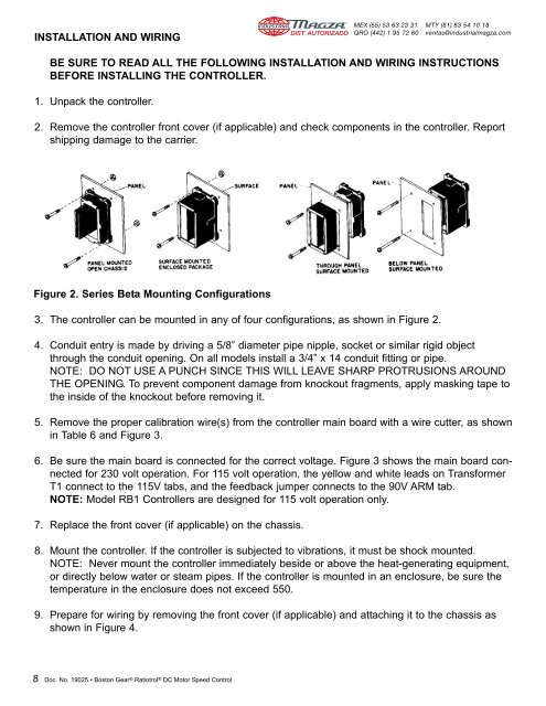
INSTALLATION AND WIRINGDIST. AUTORIZADO®MEX (55) 53 63 23 31QRO (442) 1 95 72 60MTY (81) 83 54 10 18ventas@industrialmagza.comBE SURE TO READ ALL THE FOLLOWING INSTALLATION AND WIRING INSTRUCTIONSBEFORE INSTALLING THE CONTROLLER.1. Unpack the controller.2. Remove the controller front cover (if applicable) and check components in the controller. Reportshipping damage to the carrier.Figure 2. Series <strong>Beta</strong> Mounting Configurations3. The controller can be mounted in any of four configurations, as shown in Figure 2.4. Conduit entry is made by driving a 5/8” diameter pipe nipple, socket or similar rigid objectthrough the conduit opening. On all models install a 3/4” x 14 conduit fitting or pipe.NOTE: DO NOT USE A PUNCH SINCE THIS WILL LEAVE SHARP PROTRUSIONS AROUNDTHE OPENING. To prevent component damage from knockout fragments, apply masking tape tothe inside of the knockout before removing it.5. Remove the proper calibration wire(s) from the controller main board with a wire cutter, as shownin Table 6 and Figure 3.6. Be sure the main board is connected for the correct voltage. Figure 3 shows the main board connectedfor 230 volt operation. For 115 volt operation, the yellow and white leads on TransformerT1 connect to the 115V tabs, and the feedback jumper connects to the 90V ARM tab.NOTE: Model RB1 Controllers are designed for 115 volt operation only.7. Replace the front cover (if applicable) on the chassis.8. Mount the controller. If the controller is subjected to vibrations, it must be shock mounted.NOTE: Never mount the controller immediately beside or above the heat-generating equipment,or directly below water or steam pipes. If the controller is mounted in an enclosure, be sure thetemperature in the enclosure does not exceed 550.9. Prepare for wiring by removing the front cover (if applicable) and attaching it to the chassis asshown in Figure 4.8 Doc. No. <strong>19025</strong> • Boston Gear ® Ratiotrol ® DC Motor Speed Control