
You also want an ePaper? Increase the reach of your titles
YUMPU automatically turns print PDFs into web optimized ePapers that Google loves.
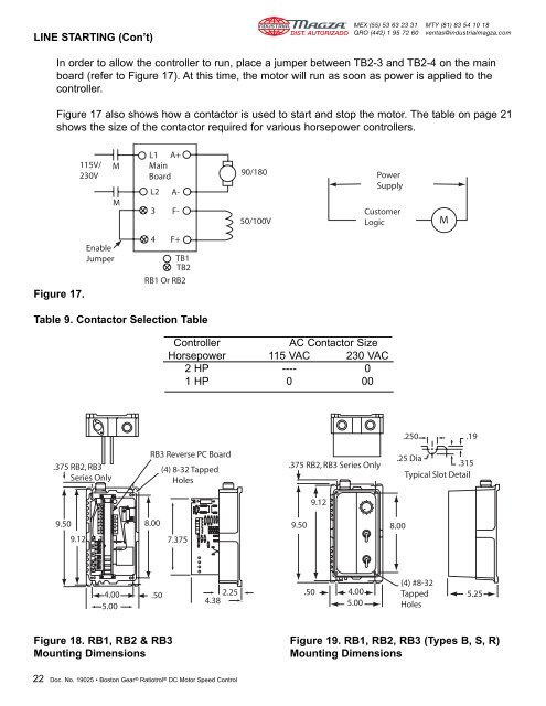
LINE STARTING (Con’t)DIST. AUTORIZADO®MEX (55) 53 63 23 31QRO (442) 1 95 72 60MTY (81) 83 54 10 18ventas@industrialmagza.comIn order to allow the controller to run, place a jumper between TB2-3 and TB2-4 on the mainboard (refer to Figure 17). At this time, the motor will run as soon as power is applied to thecontroller.Figure 17 also shows how a contactor is used to start and stop the motor. The table on page 21shows the size of the contactor required for various horsepower controllers.115V/230VMML1 A+MainBoardL2 A-3 F-90/18050/100VPowerSupplyCustomerLogicMFigure 17.EnableJumper4 F+TB1TB2RB1 Or RB2Table 9. Contactor Selection TableControllerAC Contactor SizeHorsepower 115 VAC 230 VAC2 HP ---- 01 HP 0 00.250 .19.375 RB2, RB3Series OnlyRB3 Reverse PC Board(4) 8-32 TappedHoles.375 RB2, RB3 Series Only.25 Dia.315Typical Slot Detail9.129.509.128.007.3759.508.004.005.00.502.254.38.50 4.005.00(4) #8-32TappedHoles5.25Figure 18. RB1, RB2 & RB3 Figure 19. RB1, RB2, RB3 (Types B, S, R)Mounting DimensionsMounting Dimensions22 Doc. No. <strong>19025</strong> • Boston Gear ® Ratiotrol ® DC Motor Speed Control