PDF brochure - Forkardt
PDF brochure - Forkardt
PDF brochure - Forkardt
- No tags were found...

You also want an ePaper? Increase the reach of your titles
YUMPU automatically turns print PDFs into web optimized ePapers that Google loves.
Dimensions / Performance data 3 QLC/KChuck SizeType 3QLC, 3QLK110-26* 140-35* 160-38 200-54 250-72 315-88 315-88 400-126 400-126 400-126 400-126(QLK only) (QLK_only) Z8 Z11 Z11-S12 Z15-S12 Z11-S23 Z15-S23DimensionsOuter diameter øA mm 110 140 162 210 257 320 320 400 400 400 400Bore øB +0.1 mm 26 35 38 54 72 88 88 126 126 126 126Chuck mounting øC mm Z4 120 Z5 Z6 Z8 Z8 Z11 Z11 Z15 Z11 Z15Jaw mounting/DIN6353 D S8 S9 S11 S11 S12 S12 S12 S12 S12 S23 S23Register ø of draw tube B2 H7 mm 32 39 42 65 77 93 93 134 134 134 134Mounting recess E H6 mm 100 120 140 170 220 220 300 300 380 300 380Actuator-ø F mm 45 48 52 76 90 110 110 150 150 150 150Mounting bolts QLC G - - M10 x 95 M12 x 90 M16 x 100 M16 x 100 M20 x 80 M20 x 130 M24 x 110 M20 x 130 M24 x 110Mounting bolts QLK G M10 x 80 M10 x 90 M10 x 95 M12 x 90 M16 x 100 M16 x 100 M20 x 80 M20 x 130 M24 x110 M20 x 130 M24 x 110Thread mounting QLC G1 - - M45 x 2 M68 x 2 M82 x 2 M100 x 2 M100 x 2 M140 x 2 M140 x 2 M140 x 2 M140 x 2Thread mounting QLK G1 M36 x1.5 M42 x1.5 M45 x 2 M68 x 2 M82 x 2 M100 x 2 M100 x 2 M140 x 2 M140 x 2 M140 x 2 M140 x 2Puller thread protective sleeve G2 M4 M4 M4 M5 M6 M6 M6 M6 M6 M6 M6Chuck width H mm 80 86 90 90 98 98 98 128 128 128 128Chuck width H1 mm 82 88 92 92 100 100 100 130 130 130 130Thread lengthof mounting boltsJ mm 13 18 19 20 19 21 25 24 25 24 25Thread length of actuator J1 mm 19 23 18 18 24 24 24 26 26 26 26Base jaw protr. over chuck face J2 mm 6 6 5 5 6 6 6 8 8 8 8Actuator stroke K mm 12 13 17 20 20 20 20 30 30 30 30Actuator position K1 mm 12 13 17 20 20 20 20 30 30 30 30Pitch circle - øMounting boltsL ±0.2 mm 82.6 104.8 104.8 133.4 171.4 171.4 235 235 330 235 330Pitchcircle ø of protective sleeve L1 ±0.2 mm 58.3 74 88 88 110 130 130 173 173 173 173Jaw stroke M mm 3.2 3.5 4.5 5.4 5.4 5.4 5.4 8 8 8 8Position of master jaw Nmax. mm 22.5 28 33 44.5 56.5 61 61 85 85 85 85Jaw mounting bolts O M8 M10 M12 M12 M16 M16 M16 M16 M16 M20 M20Distance P1min. mm 4 5 6 6 8 8 8 12 12 15 15Jaw mounting bolts P10 mm 13 15 17.5/14.5 27.5 34 58 58 70.5 70.5 60 60Distance P2min. mm 18 25 25/28 25 32 32 32 37 37 46 46Jaw mounting bolts P2max. mm 27 34 36.5/36.5 46.5 58 82 82 95.5 95.5 91 91Minimum distance P3 mm 14 20 19/22 19 25 25 25 25 25 31 31Minimum distance P4 mm 6.5 9.5 10 10 10 10 10 10 10 15 15Distance T-nut and serration P5 mm 2 2.5 2.5 2.5 2.5 2.5 2.5 2.5 2.5 3.5 3.5Distance T-nut and serration P6 mm 32.5 42 48 60.5 72 99 99 115 115 115 115Jaw width Q mm 25 30 35 35 45 45 45 60 60 60 60Slot width imperial Q1 H7 mm 10 12 17 17 21 21 21 21 21 25.5 25.5Slot width metric Q1 H7 mm 10 12 12 14 16 21 21 21 21 21 21Width R mm 7.5 7.6 6.6 6 10 10 10 13 13 13 13Pitch of serration/imperial QLC T - - 1/16 x 90° 1/16 x 90° 1/16 x 90° 1/16 x 90° 1/16 x 90° 1/16 x 90° 1/16 x 90° 3/32° x 90° 3/32° x 90°Pitch of serration/imperial QLK T 1/16 x 90° 1/16 x 90° 1/16 x 90° 1/16 x 90° 1/16 x 90° 1/16 x 90° 1/16 x 90° 1/16 x 90° 1/16 x 90° 3/32° x 90° 3/32° x 90°Jaw mounting metric D MS10 MS12 MS12 MS14 MS16 MS21 MS21 MS21 MS21Pitch of serration/metric QLC T - - 1.5 x 60° 1.5 x 60° 1.5 x 60° 1.5 x 60° 1.5 x 60° 1.5 x 60° 1.5 x 60°Pitch of serration/metric QLK T 1.5 x 60° 1.5 x 60° 1.5 x 60° 1.5 x 60° 1.5 x 60° 1.5 x 60° 1.5 x 60° 1.5 x 60° 1.5 x 60°Distance from 1st serration T1 mm 1.5 1.5 1.5 1.5 1.5 1.5 1.5 1.5 1.5 2.5 2.5Performance dataMax. actuating force Fmax. daN 2000 2500 2500 4000 6000 6000 6000 6000 6000 9000 9000Max. gripping force Fspmax. daN 4000 5500 6000 10000 15000 16000 16000 14000 14000 23000 23000Max. speed QLC n max. 1/min. - - 8000 6300 4500 4000 4000 3200 3200 3200 3200Max. speed QLK n max. 1/min. 8000 7500 6300 5000 4000 3500 3500 2500 2500 2500 2500Max. Gewicht Aufsatzbacke ** kg/Stck. 0.13 0.23 0.4 0.5 1.12 1.12 1.12 2.52 2.52 2.52 2.52Max. Ausladung Aufsatzbacke ** mm 30 30 40 45 55 55 55 70 70 70 70Weight G kg 5 8.5 11.5 18 26 38 38 90 90 90 90Moment of inertia QLC J kgm 2 - - 0.055 0.2 0.65 0.65 0.65 2.1 2.1 2.1 2.1Moment of inertia QLK J kgm 2 0.0075 0.02 0.04 0.095 0.2 0.65 0.65 2.1 2.1 2.1 2.1Ident – NumberImperial serration QLCD172000000 D172001000 D172002000 D172004000 D172005000 D172006000 D172007000 D172008000 D172009000 D172010000 D172011000Metric serration QLCD172012000 D172013000 D172014000 D172016000 D172017000 D172018000 D172019000 D172020000 D172021000Imperial serration QLKMetric serration QLKKDIN QLCKDIN QLK**) Limit value for max. speedD172036000 D172037000 D172038000 D172040000 D172041000 D172042000 D172043000 D172044000 D172045000 D172046000 D172047000D172048000 D172049000 D172050000 D172052000 D172053000 D172054000 D172055000 D172056000 D172057000D172024000 D172025000 D172026000 D172028000 D172029000 D172030000 D172031000 D172032000 D172033000D172060000 D172061000 D172062000 D172064000 D172065000 D172066000 D172067000 D172068000 D172069000W O R K H O L D I N G S O L U T I O N S W O R L D W I D E270.10.07 E 10/105
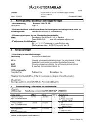
3 QLC/K - KSPower ChucksTechnical Features:• Larger through hole bore for handling largerdiameter work pieces• Multiple base jaw profile with improved guiding lengthfor greater stability• Minimal loss of lubricating grease through undercuts• Best possible clamping forces are obtained throughpatented multiple jaw guides• Improved lubrication with additional, integrated lubricantand improved forced circulation• Patented backlash free wedge hook mechanism formaximum clamping forces and highest repeatability• Centrifugal force compensation for highest speeds• Selected matching highest quality materials – all loaded,sliding surfaces are hardened and ground• Simplified construction of the guiding pistonin the chuck• Axial Stroke limitation is integrated into the designof the chucks thus ensuring any over strokeof the cylinder is not problematic• MIR / VC quick change jaw system optional3QLC-KSQQ1H1P4P5DOP1P3CTMP6T1P2L1G2øAøEøLøFG1øB2RK1 J1øBøB1øL1NmaxGJKJ26H3QLK-KSQH1Q1P4P5DOP1P3CTMT1P2P6L1G2øAøEøLøFG1øB2RK1 J1øBøB1øL1NmaxGJK270.10.07 E 10/106HJ26W O R K H O L D I N G S O L U T I O N S W O R L D W I D E
Dimensions / Performance data 3 QLC/K - KSChuck SizeType 3QLC-KS / QLK-KS 200-77 250-101 315-135 400-168D i m e n s i o n sOuter diameter øA mm 210 257 320 400Bore øB +0.1 mm 77 101 135 168Chuck mounting øC mm Z6 Z8 Z11 Z15Jaw mounting/DIN 6353 D S11 S11 S12 S12Register Ø of draw tube B2 H7 mm 85 112 140 173Mounting recess E H6 mm 170 220 300 380Actuator Ø F mm 97 123 153 190Mounting bolts G M12 x 90 M16 x 95 M20 x 90 M24 x 80Thread mounting G1 M90 x 2 M115 x 2 M145 x 2 M180 x 2Puller thread protective sleeve G2 M5 M5 M6 M6Chuck width H mm 90 90 98 98Chuck width H1 mm 92 92 100 100Thread length of mounting bolts J mm 20 22 22 30Thread length of actuator J1 mm 24 24 24 24Base jaw protrusion over chuck face J2 mm 5 5 6 6Actuator stroke K mm 18.5 20 20 20Actuator position K1 mm 18.5 20 20 20Pitch circle Ø of Mounting bolts L ±0.2 mm 133.4 171.4 235 330.2Pitch circle Ø of protective sleeve L1 ±0.2 mm 100 129 173 210Jaw stroke M mm 5 5.3 5.3 5.3Position of master jaw Nmax mm 52.5 67.5 85 100.5Jaw mounting bolts O M12 M12 M16 M16Distance P1min mm 6 6 8 8Jaw mounting bolts P1max mm 20 29 34 58Distance P2min mm 25 25 32 32Jaw mounting bolts P2max mm 39 48 58 82Minimum distance P3 mm 19 19 24 24Minimum distance P4 mm 10 10 10 10Distance T-nut and serration P5 mm 2.5 2.5 2.5 2.5Length of serrations P6 mm 52.5 61 75 99.5Jaw width Q mm 35 35 45 45Slot width imperial Q1 H7 mm 17 17 21 21Slot width metric Q1 H7 mm 12 14 16 21Width R mm 6.6 6.6 9.6 9.6Pitch of serration / imperial T 1/16” x 90° 1/16” x 90° 1/16” x 90° 1/16” x 90°Jaw mounting metric D MS12 MS14 MS16 MS21Pitch of serration metric T 1.5 x 60° 1.5 x 60° 1.5 x 60° 1.5 x 60°Distance from 1st serration T1 mm 1.5 1.5 1.5 1.5P e r f o r m a n c e d a t aMax. actuating force Fmax daN 2,500 4,000 6,000 6,000Max. gripping force Fspmax daN 6,000 10,000 15,000 16,000Max. speed QLC-KS nmax 1/min 6,300 5,000 4,000 3,200Max. speed QLK-KS nmax 1/min 5,000 4,200 3,000 2,800Weight G kg 16 26 37 63Moment of inertia QLC-KS kgm 2 0.076 0.18 0.4 1.04Moment of inertia QLK-KS kgm 2 0.076 0.175 0.4 1.04I d e n t – N u m b e rImperial serration QLC-KS D170130000 D172073000 D168480000 D168481000Metric serration QLC-KS D168718000 D168719000 D168720000 D168721000Imperial serration QLK-KS D170131000 D168576000 D168577000 D168578000Metric serration QLK-KS D170132000 D168538000 D168539000 D168540000270.10.07 E 10/10W O R K H O L D I N G S O L U T I O N S W O R L D W I D E7
2/3 QLC – LSPower ChucksTechnical Features:• 95 % more clamping stroke for work pieceswith variations in diameter• Easily grip stepped work pieces• Available as 2- and 3-jaw QLC versions(QLK variants not available)• Multiple base jaw profile with improved guidinglength for greater stability• Minimal loss of lubricating grease throughundercuts• Nitrided chuck body for longer service life• Selected matching highest quality materials – allloaded, sliding surfaces are hardened and ground• Long maintenance intervals• Centrifugal force compensation for highest speeds2QLC-LSQQ1H1P4P5DOP1P3CTP2P6L1G2øAøEøLøFG1øB2K1RJ1T1øBøL1MNmaxGJKJ26H3QLC-LSQQ1H1P4P5DOP1P3CTP2P6L1øAøEøLøFG1øB2K1RJ1T1øBøL1MNmaxG2GJK270.10.07 E 10/106HJ28W O R K H O L D I N G S O L U T I O N S W O R L D W I D E
Dimensions / Performance data 2/3 QLC - LSChuck SizeTyp 2QLC-LS / 3QLC-LS 160-30 200-41 250-52 315-71D i m e n s i o n sOuter diameter øA mm 162 210 257 320Bore øB +0.1 mm 30 41 52 71Chuck mounting øC mm Z5 Z6 Z8 Z11Jaw mounting/DIN 6353 D S11 S11 S12 S12Register Ø of draw tube B2 H7 mm 42 65 77 93Mounting recess E H6 mm 140 170 220 300Actuator Ø F mm 52 76 91 110Mounting bolts G M10 x 95 M12 x 100 M16 x 110 M20 x 90Thread mounting G1 M45 x 2 M68 x 2 M82 x 2 M100 x 2Puller thread protective sleeve G2 M4 M5 M6 M6Chuck width H mm 93 96 110 120Chuck width H1 mm 95 98 112 122Thread length of mounting bolts J mm 15.7 19 20 25Thread length of actuator J1 mm 23.4 24 24 24Base jaw protrusion over chuck face J2 mm 5 5 6 6Actuator stroke K mm 20 23 27 32Actuator position K1 mm 20 23 27 32Pitch circle Ø of Mounting bolts L ±0.2 mm 104.8 133.4 171.4 235Pitch circle Ø of protective sleeve L1 ±0.2 mm 88 96 120 140Jaw stroke M mm 8 9.3 10.9 12.9Position of master jaw Nmax mm 36 43.7 52.9 70.5Jaw mounting bolts O M12 M12 M16 M16Distance P1min mm 6 6 8 8Jaw mounting bolts P1max mm 14 35 40 58Distance P2min mm 25 25 32 32Jaw mounting bolts P2max mm 33 49 58 82Minimum distance P3 mm 19 19 24 24Minimum distance P4 mm 10 10 10 10Distance T-nut and serration P5 mm 2.5 2.5 2.5 2.5Length of serrations P6 mm 45 61 75.5 89Jaw width Q mm 35 35 45 45Slot width imperial Q1 H7 mm 17 17 21 21Slot width metric Q1 H7 mm 12 14 16 21Width R mm 6.6 6.6 9.6 9.6Pitch of serration / imperial T 1/16" x 90° 1/16" x 90° 1/16" x 90° 1/16" x 90°Jaw mounting metric D MS12 MS14 MS16 MS21Pitch of serration metric T 1.5 x 60° 1.5 x 60° 1.5 x 60° 1.5 x 60°Distance from 1st serration T1 mm 1.5 1.5 1.5 1.5P e r f o r m a n c e d a t aMax. actuating force 2QLC-LS Fmax daN 2,400 3,700 4,600 5,700Max. gripping force 2QLC-LS Fspmax daN 3,700 6,000 7,500 10,000Max. actuating force 3QLC-LS Fmax daN 3,500 5,500 7,000 8,500Max. gripping force 3QLC-LS Fspmax daN 5,500 9,000 11,000 15,000Max. speed nmax 1/min 6,000 5,500 4,000 3,200Weight G kg 9 18 31 50Moment of inertia kgm 2 0.028 0.09 0.25 0.6I d e n t – N u m b e rImperial serration 2QLC-LS D169619000 D169621000 D169622000 D169623000Metric serration 2QLC-LS D169817000 D169818000 D169819000 D169820000Imperial serration 3QLC-LS D169563000 D169565000 D169566000 D169567000Metric serration3QLC-LS 3QLC-LS D169813000 D169813000 D169814000 D169814000 D169815000 D169815000 D169816000 D169816000**) Limit value for max. speed ** Pitch of serration metric * Pitch of serration / imperial270.10.07 E 10/109
3 QLC – AGPower ChucksTechnical Features:• Compensating chuck to clamp off-center partswith high precision• Easy moving compensation even at highclamping forces• Ingenious pull-back action for improvedpart location on center• Easily interchangeable and finely adjustablecenter housings• Simple change-over for self-centering modefor general chucking work• Centrifugal force compensation for highestspeeds (QLK variants not available)• Axial stroke limitation is integrated,ensuring any over stroke of the cylinderis not problematic3QLC-AGQQ1CH1P5P4OP3 P1P2J1K1øAøEM1T1TøLøFP6G1MNmaxJKGH2270.10.07 E 10/106H3H10W O R K H O L D I N G S O L U T I O N S W O R L D W I D E
Dimensions / Performance data 3 QLC - AGChuck SizeType 3QLC-AG 200 250 315D i m e n s i o n sOuter diameter øA mm 210 257 315Bore øB mm 0 0 0Chuck mounting øC mm Z6 Z8 Z8Jaw mounting D S11 S12 S12Mounting recess E mm 170 220 220Actuator Ø F mm 44 50 50Mounting bolts G 3 x M12 3 x M16 3 x M16Thread mounting G1 M20 M24 M24Chuck width H mm 106 113 113Chuck back to serration H1 mm 108 115 115Point height H2 mm 18 22 22Pull-back stroke H3 mm 0.2 0.2 0.2Thread length of mounting bolts J mm 18 24 24Thread length of actuator J1 mm 40 45 45Actuator stroke K mm 20 20 20Actuator position K1 mm 45 55 55Pitch circle Ø Mounting bolts L mm 133.4 171.4 171.4Jaw stroke M mm 5.3 5.3 5.3Compensating stroke M1 mm 2 2 2Position of master jaw Nmax mm 42.9 53.5 55.5Jaw mounting bolts O M12 M16 M16Distance P1min mm 6 8 8Jaw mounting bolts P1max mm 34 41 65Distance P2min mm 25 32 32Jaw mounting bolts P2max mm 53 65 89Minimum distance P3 mm 19 24 24Minimum distance P4 mm 10 10 10Distance T-nut and serration P5 mm 2.5 2.5 2.5Length of serrations P6 mm 61 75 99.5Jaw width Q mm 35 45 45Slot width / imperial Q1 mm 17 21 21Pitch of serration / imperial T 1/16" x 90° 1/16" x 90° 1/16" x 90°P e r f o r m a n c e d a t aMax. actuating force Fmax daN 3,600 5,000 5,500Max. gripping force Fspmax daN 7,000 12,000 13,000Max. speed nmax 1/min 4,700 4,500 4,000Weight G kg 21 32 44Moment of inertia J kgm 2 0.11 0.3 0.8I d e n t – N u m b e rImperial serration D170783000 D170393000 D169907000Metric serration D170788000 D170789000 D170790000Note: QLC-AG chucks may optionally be equipped with spring loaded centres or inserts for concentric operation.**) Limit value for max. speed270.10.07 E 10/10W O R K H O L D I N G S O L U T I O N S W O R L D W I D E11
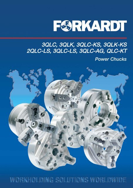
V13 QLC – KTPower ChucksPower chuck for highest standardsIn order to fulfil highest requirements the wellestablishedQLC power chuck was altered towards asolid version without bore.The combination of the patented base jaw guidingshape of the QLC chucks with the rigidity of KTchucks provided chuck characteristics perfectlysuitable for heavy cutting applications.The QLC-KT chucks are determined to be used withhigh clamping forces plus extraordinary accuracy.Technical Features:• Maximum Gripping force• Maximum Speed• Quick jaw change• MIR, VC quick change jaw systemoptionalExample:3 QLC-KT 400 Performance dataMax. = 26 000 daNgripping forceMax. rpm = 3200 1/min3QLC-KTA-AB-BA6H1P4OP1BBJ1øAC/øEøLøFG1L1NP3P2P6Q1K1KQG2GT1AJH270.10.07 E 10/10Chuck mounting Z12W O R K H O L D I N G S O L U T I O N S W O R L D W I D E
Dimensions / Performance data 3 QLC- KTAbbreviation explanation for chuck mountingsCylindrical recess DIN 6353FORKARDT DIN Mounting recess Pitch circleType designation Size H6Z5 5 ø 140 Ø 104.8 with M10Z6 6 ø 170 Ø 133.4 with M12Z8 8 ø 220 Ø 171.4 with M16Z11 11 ø 300 Ø 235.0 with M20Z15 15 ø 380 Ø 330.2 with M24Short taper - direct recess DIN 55026 shape AFORKARDT DIN Taper-Ø Pitch circleType designation Size d2K5 5 82.573 Ø 104.8 with M10K6 6 106.385 Ø 133.4 with M12K8 8 139.731 Ø 171.4 with M16K11 11 196.883 Ø 235.0 with M20K15 15 283.791 Ø 330.2 with M24Short taper - bayonet mounting DIN 55027FORKARDT DIN Taper-Ø Pitch circleType designation Size d2J5 5 82.573 Ø 104.8 with M10J6 6 106.385 Ø 133.4 with M12J8 8 139.731 Ø 171.4 with M16J11 11 196.883 Ø 235.0 with M20J15 15 283.791 Ø 330.2 with M24Ident-Numbers and connecting dimensions - Performance dataChuck type Ident-No. and mounting dimensions DimensionsChuck mountingPitch of serrationCross tenonQuick change jaw system VCOuter diameter AJaw width QMounting thread G1Chuck width HMax. actuating force FmaxMax. Clamping force FSPmaxMax. speed nmaxmm mm mm daN daN min -13QLC-KT 160 Z5 S11 D174005000 D174007000 D174008000 184 40 M16 114 3,000 7,000 7,0003QLC-KT 160 K5 S11 D174010000 D174012000 D174013000 184 40 M16 114 3,000 7,000 7,0003QLC-KT 200 Z6 S11 D174025000 D174027000 D174005000 200 40 M20 124 5,000 11,500 6,0003QLC-KT 200 K6 S11 D174030000 D174032000 D174005000 200 40 M20 124 5,000 11,500 6,0003QLC-KT 250 Z8 S11 D174045000 D174047000 D174005000 250 50 M24 142 7,500 16,000 5,0003QLC-KT 250 Z8 S11 D174050000 D174052000 D174005000 250 50 M24 152 7,500 16,000 5,0003QLC-KT 315 Z8 S11 D174065000 D174067000 D174005000 315 50 M24 142 8,000 17,000 4,0003QLC-KT 315 K8 S11 D174070000 D174072000 D174005000 315 50 M24 8,000 17,000 4,0003QLC-KT 315 Z11 S11 D174832000 D174834000 D174005000 315 50 M24 142 8,000 17,000 4,0003QLC-KT 400 Z11 S12 D174840000 400 60 M30 181 7,300 16,000 3,2003QLC-KT 400 Z15 S12 D174836000 400 60 M30 181 7,300 16,000 3,2003QLC-KT 400 Z11 S23 D174085000 D174087000 D174088000 400 60 M30 181 12,000 26,000 3,2003QLC-KT 400 K11 S23 D174090000 D174092000 D174093000 400 60 M30 12,000 26,000 3,2003QLC-KT 400 Z15 S23 D174841000 D174838000 D174839000 400 60 M30 181 12,000 26,000 3,200270.10.07 E 10/10W O R K H O L D I N G S O L U T I O N S W O R L D W I D E13
V13QLC-KT with jaw mounting SChuck SizeType 3QLC-KT 160 200 250 250 315 315 400 400 400DimensionsOuter diameter A mm 184 200 250 250 315 315 400 400 400Bore B mm - - - - - - - - -Chuck mounting C Z5 Z6 Z8 K8 Z8 Z11 Z11 Z11 Z15Jaw mounting D 1) S11 S11 S12 S12 S12 S12 S12 S23 S23T 1) (1/16"x 90°) (1/16"x 90°) (1/16"x 90°) (1/16"x 90°) (1/16"x 90°) (1/16"x 90°) (1/16"x 90°) (3/32"x 90°) (3/32"x 90°)Mounting recess E mm 140 H6 170 H6 220 139.731 220 H6 300 H6 300 H6 300 H6 380 H6Actuator F mm 34 50 52 52 52 52 68 68 68Mounting bolts G M10 (3x) M12 (3x) M16 (3x) M16 (3x) M16 (3x) M20 (3x) M20 (3x) M20 (3x) M24 (3x)Thread mounting G1 M16 M20 M24 M24 M24 M24 M30 M30 M30Thread mounting G2 M6 M6 M6 M6 M6 M6 M10 M10 M10Chuck width H mm 114 124 142 152 142 142 177 177 177H1 1) mm 120 130 150 160 150 150 185 185 185Thread length J mm 15 18 24 24 24 30 30 30 30Thread length of actuator J1 mm 40 45 56 56 56 56 55 55 55Actuator stroke K mm 20 20 26 26 26 26 32 32 32Actuator position K1 mm 25 30 30 30 30 30 30 30 30Pitch circle-Ø L mm 104.8 133.4 171.4 171.4 171.4 235 235 235 330.2Mounting bolts L1 mm 60 70 105 105 105 235 235 235 330.2Jaw stroke M mm 5.3 6.5 8 8 8 8 10 10 10Position of master jaw N 1) mm 31.7 40.1 48 48 48 48 70 70 70Jaw mounting bolts O 1) M12 M12 M16 M16 M16 M16 M16 M20 M20Distance min. P1 1) mm 10 10 12 12 12 12 12 14 14Jaw mounting boltDistance max. P2 1) mm 50.2 50.3 55.5 55.5 96 96 118 115 115Jaw mounting boltMinimum distance P3 1) mm 19 19 25 25 25 25 25 31 31Minimum distance P4 1) mm 9 9 10 10 10 10 10 14 14Length of serrations P6 mm 60.3 59.9 77 77 109.5 109.5 130 130 130Jaw width Q mm 40 40 50 50 50 50 50 60 60Slot width Q1 1) mm 17 H7 17 H7 21 H7 21 H7 21 H7 21 H7 21 H7 25.5 H7 25.5 H7Distance from 1st serration T1 1) mm 1.5 1.5 1.5 1.5 1.5 1.5 1.5 2.5 2.5T-slot width V1 mm 14 14 18 18 18 18 22 22 22Performance dataMax. actuating force FAX 1) daN 3,000 5,500 7,500 7,500 8,000 8,000 7,300 12,000 12,000Max. speed n n min -1 7,000 6,000 5,000 5,000 4,000 4,000 3,200 3,200 3,200Max. gripping force FSP 1) daN 7,000 11,500 16,000 16,000 17,000 17,000 16,000 26,000 26,000Weight G kg 21 27 51 51 81 81 163 163 1631) valid only for jaw mounting SA-AB-BA6H1P4BBøAC/øEøLøFG1J1NL1Q1K1KGOP1H1P3P2P67°7'30"T1QG2C/øEshort taperDIN 55028K1G270.10.07 E 10/10AJHChuck mounting ZJHChuck mounting K, J14W O R K H O L D I N G S O L U T I O N S W O R L D W I D E
N3QLC-KT with jaw mounting KDINChuck SizeType 3QLC-KT 200 250 315 400DimensionsChuck mounting C mm Z6 Z8 Z8 / Z11 Z11 / Z15Jaw mounting D KDIN KDIN KDIN K 25Chuck width H1 2) mm 130 150 150 185Jaw position N 2) mm 70 88 100 13.5Jaw mounting bolt O 2) M12 M16 M16 M20Distance jaw mounting bolt P1 2) mm 30 40 50 70Minimum distance P4 2) mm 9 12 10 20Slot width Q1 2) mm 16 H7 20 H7 20 H7 25 H7Feather key width Q2 2) mm 12 g6 16g6 16g6 25g6Performance dataMax. actuating force FAX 2) daN 5,500 7,500 8,000 12,000Max. gripping force FSP 2) daN 11,500 16,000 17,000 26,000Max. speed nmax 1/min 6,000 5,000 4,000 3,2002) valid only for jaw mounting KDIN – other dimensions see jaw mounting SQ1H1P4DH1O1O1OK1GQ2Short taperDIN 55028K1GJJChuck mounting ZChuck mounting K, J3QLC-KT with jaw mounting VCChuck SizeType 3QLC-KT 160 200 250 315 400DimensionsChuck mounting C mm Z5 Z6 Z8 Z8 / Z11 Z11 / Z15Jaw mounting D VC11 VC21 VC22 VC22 VC31Chuck width H1 3) mm 130.5 143 163 163 206Jaw position N 3) mm 55.9 70 86.5 103 135Performance dataMax. actuating force FAX 3) daN 3,000 5,500 7,500 8,000 12,000Max. gripping force FSP 3) daN 7,000 11,500 16,000 17,000 26,000Max. speed nmax 1/min 7,000 6,000 5,000 4,000 3,2003) valid only for jaw mounting VC – other dimensions see jaw mounting SH1H1DNShort taperDIN 55028K1K1GJChuck mounting ZGJChuck mounting K, J270.10.07 E 10/10W O R K H O L D I N G S O L U T I O N S W O R L D W I D E15
Mounting Flanges, Adaptors and Adaptor Plates:Flanges with bayonet plate attachment for mounting on spindle J nosesto DIN 55022, DIN 55027, ISO 702 / IIISpindle nose Flange type Ident. No. Dimensions Studs and collar nutsSize B D L1 L2 FN Ident. No. Qty.4 FF100-J4 D1074085000 45 18 82.6 85.0 322 D1070505000 35 FF120-J5 - 50 24 104.8 104.8 322 D1070505000 45 FF140-J5 D1074086000 50 24 104.8 104.8 322 D1070505000 446 FF170-J6 D1074090000 65 28 133.4 133.4 322 D1070506000 48 FF220-J8 D1074097000 80 32 171.4 171.4 322 D1070507000 411 FF300-J11 D1074104000 90 35 235.0 235.0 322 D1070508000 615 FF380-J15 D1074108000 120 42 330.2 330.2 324 D1070517000 6Order code example: 1 mounting flange type FF 170-J6, Ident. No. D1074090000,1 set of studs with collar nuts size 6, Ident. No. D1070506000JB L2L1DMounting Flanges JFlanges with camlock attachment for mounting on spindle D nosesto DIN 55029, ISO 702 / II, ASA B 5.9 D1DSpindle nose Flange type Ident. No. Dimensions Camlock studsSize B D L1 L2 FN Ident. No. Qty.4 FF100-D4 - 45 28 82.6 82.6 286 D1070511000 35 FF120-D5 - 50 30 104.8 104.8 287 D1070512000 65 FF140-D5 D1074119000 50 30 104.8 104.8 287 D1070512000 66 FF170-D6 D1074123000 65 35 133.4 133.4 288 D1070513000 68 FF220-D8 D1074130000 80 40 171.4 171.4 289 D1070514000 611 FF300-D11 D1074137000 90 45 235.0 235.0 289 D1070515000 615 FF380-D15 D1074141000 120 50 330.2 330.2 291 D1070516000 6Order code example: 1 mounting flange type FF 170 - D6, Ident. No. D1074123000, 1 set of camlock studs size 6, Ident. No. D1070513000B L2L1DMounting Flanges DAdaptor flanges including mounting bolts for spindle nosesDIN 55021 A/B, DIN 55026 A/B, ISO 702/I A1/A2, ASA B5.9 A1/A2KSpindle nose Flange type Ident. No. Dimensions Mounting boltsSize B D L1 L2 DIN 912 10.93 ZWF100-K3 - 35 18 70.6 82.6 3 x M10 x 204 ZWF120-K4 - 50 20 82.6 104.8 3 x M10 x 204 ZWF140-K4 D1074053000 50 20 85.0 104.8 3 x M10 x 204 ZWF140-K4 D1074053000 50 18 104.8 85.04 ZWF140-K4 D1044757000 50 18 104.8 82.63 x M10 x 205 ZWF170-K5 D1074056000 60 24 133.4 104.8 4 x M10 x 256 ZWF220-K6 D1074060000 80 28 171.4 133.4 4 x M12 x 308 ZWF300-K8 D1074065000 90 32 235.0 171.4 4 x M16 x 3511 ZWF380-K11 D1074068000 120 35 330.2 235.0 6 x M20 x 40DIN 55021 Pitch circle diameter 85 mm DIN 55026 Pitch circle diameter 82.6 mm Order code example, 1 adapter flange ZWF 140 - K4,Ident. No. D1044757000DAdaptor FlangesZWFBL2L1Adaptor plates for spindle noses to DIN 55021 A,DIN 55026 A, ISO 702/I A2, ASA B 5.9K A2270.10.07 E 10/10Spindle nose Flange type Ident. No. DimensionsSize D L2 L*4 ZWS100-K4 - 12 82.6 105 ZWS120-K5 - 14 104.8 155 ZWS140-K5 D1074035000 14 104.8 156 ZWS170-K6 D1074036000 15 133.4 158 ZWS220-K8 D1074038000 17 171.4 1511 ZWS300-K11 D1074040000 19 235.0 2015 ZWS380-K15 D1074042000 21 330.2 20*The length of the chuck mounting bolts must be increased by the amount "L"when using these adapter plates!Order code example: 1 adaptor plate ZWS-K5. Ident. No. D1074035000.Note: The respective chuck type must be clearly specified when ordering flanges or adaptors separately.DAdaptor PlatesZWSL2L116W O R K H O L D I N G S O L U T I O N S W O R L D W I D E
VCV-Change - Quick changeJaw system VCThe quick change jaw system VC is as simple inhandling as effective in reduction of the set-up time.In spite of the same repeatability and less spacerequirement - compared to general mounting systems- very high clamping forces are permitted as well.Therefore, this quick change jaw system inconnection with a high-quality chuck represents aneconomic problem solution to improve productivity.Advantages at a glance:• Jaw change within seconds• For I.D. and O.D. clamping• Jaw change system easily to be realisedautomatically• Best repeatabilityPAT E N T E D270.10.07 E 10/10W O R K H O L D I N G S O L U T I O N S W O R L D W I D E17
VCSoft Top Jaws VCO.D. clampingATTENTION: Treatment permissible just outside the –--– mounting!Soft Top JawsV-ChangeEXTERNALMaterial: Heat treatable42CrMo4Jaw Dimensions (mm) Weight Min. clampingChuck type type Ident No. A B C D E F G H I Kg./each diameter (mm)QLC 160 VC 11 VC 1120D174546000 85 40 60 46 10 35 31 17 50 1.3QLC KT 160 VC 11 VC 11 25QLC 200 VC 21 VC 2130D174548000 105 40 60 59 10 40 38 20 50 1.6QLC KT 200 VC 21 VC 21 10QLC 250 VC 22 VC 22 30QLC KT 250 VC 22 VC 2212D174550000 120 60 80 74 10 40 45 20 67.5 3.9QLC 315 VC 22 VC 22 65QLC KT 315 VC 22 VC 22 45QLC 400 VC 31 VC 31105D174552000 152 60 80 90 10 54 60 22 59.5 4.4QLC KT 400 VC 31 VC 31 75I.D. clampingATTENTION: Treatment permissible just outside the –--– mounting!Soft Top JawsV-ChangeINTERNALMaterial: Heat treatable42CrMo4270.10.07 E 10/1018Jaw Dimensions (mm) Weight Min. clampingChuck type type Ident No. A B C D E F G H I Kg./each diameter (mm)QLC 160 VC 11 VC 11D174547000 91 40 60 46 10 35 31 17 50 1.4 25QLC KT 160 VC 11 VC 11QLC 200 VC 21 VC 2145D174549000 99 40 60 59 10 40 38 20 50 1.5QLC KT 200 VC 21 VC 21 35QLC 250 VC 22 VC 22 45QLC KT 250 VC 22 VC 2235D174551000 120 60 80 74 10 40 45 20 67.5 4.0QLC 315 VC 22 VC 22 90QLC KT 315 VC 22 VC 22 70QLC 400 VC 31 VC 31150D174553000 155 60 80 90 10 54 60 22 59.5 4.4QLC KT 400 VC 31 VC 31 100W O R K H O L D I N G S O L U T I O N S W O R L D W I D E
NSTKT-sliding blockGeneralAs a further highlight of our jaw holder system,<strong>Forkardt</strong> offers the NSTK T-sliding block.Changing or adjusting chuck jaws to a differentclamping diameter involves lengthy setting-upoperations.Example:1st operation:2nd operation:Chuck jaws withgripping clawsChuck jaws withturned insidediameterThe new jaw holder system consists of theNSTK T-sliding block and soft jaws for use witheither SKA or SKI clamping inserts for the firstoperation or for turning to the required clampingdiameter under clamping pressure forgreater setting up efficiency.Features• Standardised soft top jaws – for individualapplications.• Claw jaws for internal and external chuckingwith SKA and SKI clamping inserts.• A more variable and wider clamping range isoffered by the added option of shifting the chuckjaw and T-sliding block.• Free arrangement without restrictions throughholes compared to conventional WBL systemwith screw fixing.• Rapid jaw shifting and changing.• Suitable for use on all <strong>Forkardt</strong> chuckswith serrated jaws in inches.• Chuck sizes from160 m to 630 mm diameter.• Simplified jaw changingon pick-up machines.270.10.07 E 10/10W O R K H O L D I N G S O L U T I O N S W O R L D W I D E19
WBLKL Soft Block JawsDimensions /Performance data WBLKLChuck Jaw type Ident No. WeighttypeeachjawA B C D B1 B2 C1 J (kg)3QLC/QLK 160 WBLKL 11 60 40 50 S11 D175384000 17 23.5 32 12 0.93QLC/QLK 200 WBLKL 11 80 40 50 S11 D175239000 17 23.5 32 12 1.23QLC/QLK 250 WBLKL 12 110 50 70 S12 D174913000 21 29.5 40 18 2.93QLC/QLK 315 WBLKL 12 110 50 70 S12 D174913000 21 29.5 40 18 2.93QLC/QLK 400 WBLKL 12 110 50 70 S12 D174913000 21 29.5 40 18 2.93QLC/QLK 400 WBLKL 23 140 60 80 S23 D175241000 25.5 37 50 20 5.23NH/NHF 500 WBLKL 23 140 60 80 S23 D175241000 25.5 37 50 20 5.23NH/NHF 630 WBLKL 23 140 60 80 S23 D175241000 25.5 37 50 20 5.2KBNKLA Roughing Jawswith interchangeable chucking clawsF O R O . D .Accessories:SKAHardchucking clawsMaterial:Insert steel,hardenedSKA for O.D.KBNKLI Roughing Jawswith interchangeable chucking clawsF O R I . D .Accessories:SKIHardchucking clawsMaterial:Insert steel,hardened5 serrationsfrom dimension F= 37through hole for socket head screwG x J DIN 79845 serrations from dimension F= 38through hole for socket head screwG x J DIN 7984270.10.07 E 10/1020SKI for I.D.T-sliding block S11 = 174540000T-sliding block S12 = 174339000T-sliding block S23 = 174541000S11 = Groove 17 and pitch of serration 1/16” x 90°S12 = Groove 21 and pitch of serration 1/16” x 90°S23 = Groove 25.5 and pitch of serration 3/32” x 90°W O R K H O L D I N G S O L U T I O N S W O R L D W I D E
KBNKLA Roughing Jawswith interchangeable chucking claws • F O R O . D .Dimensions /Performance data KBNKLAChuck- Jaw type Ident No. Clamping max. Gravity Weight Individual part - Ident No.type range swing center each Jawdiameter distance jaw without hard Locatorchucking chuckingA B C D Xs A1 B1 B2 M1 J (kg) claw claw3QLC/QLK 8 40 50 S11 D175378000 30.5 -76.5 186 29.5 60 17 23.5 4.6 14 0.59 D175378001 D45474002160 KBNKLA 11 22 40 50 S11 D175379000 61 -105 186 31.7 60 17 23.5 4.6 14 0.55 D175379001 D45474002 D4546300333 40 50 S11 D175380000 80 -126 186 33.9 60 17 23.5 4.6 14 0.54 D175380001 D454740023QLC/QLK 10 40 50 S11 D174957000 44 -88 232 39.1 80 17 23.5 4.6 14 0.80 D174957001 D45474002200 KBNKLA 11 32 40 50 S11 D174958000 88 -134 232 44.35 80 17 23.5 4.6 14 0.72 D174958001 D45475002 D4546300350.2 40 50 S11 D174959000 125 -170 232 46.5 80 17 23.5 4.6 14 0.64 D174959001 D454750023QLC/QLK 12.6 50 70 S12 D174960000 63 -141 338 53.0 110 21 29.5 6.3 18 1.86 D174960001 D45482002250 KBNKLA 12 47.7 50. 70 S12 D174961000 131 -210 338 58.4 110 21 29.5 6.3 18 1.65 D174961001 D45483002 D17615100281.0 50 70 S12 D174962000 197 -277 338 67.2 110 21 29.5 6.3 18 1.73 D174962001 D454830023QLC/QLK 12.6 50 70 S12 D174960000 89 -202 399 53.0 110 21 29.5 6.3 18 1.86 D174960001 D45482002315 KBNKLA 12 65.2 50 70 S12 D174963000 193 -307 399 67.1 110 21 29.5 6.3 18 1.77 D174963001 D45483002 D17615100281.0 50 70 S12 D174962000 225 -339 399 67.2 110 21 29.5 6.3 18 1.73 D174962001 D454830023QLC/QLK 12.6 50 70 S12 D174960000 121 -268 464 53.0 110 21 29.5 6.3 18 1.86 D174960001 D45482002400 KBNKLA 12 65.2 50 70 S12 D174961000 225 -373 464 58.4 110 21 29.5 6.3 18 1.65 D174961001 D45483002 D17615100281.0 50 70 S12 D174962000 251 -404 464 67.2 110 21 29.5 6.3 18 1.73 D174962001 D454830023QLC/QLK KBNKLA 23 22.0 60 80 S23 D175213000 101 -292 533 70.86 140 25.5 37 12 22 3.25 D175213001 D45488002400 83.5 60 80 S23 D175214000 224 -414 533 77.7 140 25.5 37 12 22 2.75 D175214001 D45489002 D454750033NH/ NHF KBNKLA 23 22.0 60 80 S23 D175213000 131 -393 633 70.86 140 25.5 37 12 22 3.25 D175213001 D45488002500 83.5 60 80 S23 D175214000 253 -515 633 77.7 140 25.5 37 12 22 2.75 D175214001 D45489002 D454750033NH/NHF KBNKLA 23 22.0 60 80 S23 D175213000 154 -522 762 70.86 140 25.5 37 12 22 3.25 D175213001 D45488002630 83.5 60 80 S23 D175214000 276 -645 762 77.7 140 25.5 37 12 22 2.75 D175214001 D45489002 D45475003A B C D Xs A1 B1 B2 M1 J (kg)3QLC/K-KS 10 40 50 S11 D174957000 44 - 88 232 39.1 80 17 23.5 4.6 14 0.80 D174957001 D45474002200 KBNKLA 11 32 40 50 S11 D174958000 88 - 134 232 44.35 80 17 23.5 4.6 14 0.72 D174958001 D45475002 D4546300350.2 40 50 S11 D174959000 125 - 170 232 46.5 80 17 23.5 4.6 14 0.64 D174959001 D454750023QLC/K-KS 10 40 50 S11 D174957000 85 - 129 278 39.1 80 17 23.5 4.6 14 0.80 D174957001 D45474002250 KBNKLA 11 32 40 50 S11 D174958000 122 - 174 278 44.35 80 17 23.5 4.6 14 0.72 D174958001 D45475002 D4546300350.2 40 50 S11 D174959000 165 - 210 278 46.5 80 17 23.5 4.6 14 0.64 D174959001 D454750023QLC/K-KS 12.6 50 70 S12 D174960000 125 - 202 399 53.0 110 21 29.5 6.3 18 1.86 D174960001 D45482002315 KBNKLA 12 47.7 50 70 S12 D174961000 193 - 307 399 58.4 110 21 29.5 6.3 18 1.65 D174961001 D45483002 D17615100281 50 70 S12 D174962000 260 - 340 399 67.2 110 21 29.5 6.3 18 1.73 D174962001 D454830023QLC/K-KS 12.6 50 70 S12 D174960000 168 - 282 480 53.0 110 21 29.5 6.3 18 1.86 D174960001 D45482002400 KBNKLA 12 65.2 50 70 S12 D174963000 273 - 387 480 67.1 110 21 29.5 6.3 18 1.77 D174963001 D45483002 D17615100281 50 70 S12 D174962000 305 - 418 480 67.2 110 21 29.5 6.3 18 1.73 D174962001 D45483002A B C D Xs A1 B1 B2 M1 J (kg)2/3QLC-LS 8 40 50 S11 D175378000 30.5-76.5 186 29.5 60 17 23.5 4.6 14 0.59 D175378001 D45474002160 KBNKLA 11 22 40 50 S11 D175379000 61 -105 186 31.7 60 17 23.5 4.6 14 0.55 D175379001 D45474002 D4546300333 40 50 S11 D175380000 80 -126 186 33.9 60 17 23.5 4.6 14 0.54 D175380001 D454740022/3QLC-LS 10 40 50 S11 D174957000 44 -88 232 39.1 80 17 23.5 4.6 14 0.80 D174957001 D45474002200 KBNKLA 11 32 40 50 S11 D174958000 88 -134 232 44.35 80 17 23.5 4.6 14 0.72 D174958001 D45475002 D4546300350.2 40 50 S11 D174959000 125 -170 232 46.5 80 17 23.5 4.6 14 0.64 D174959001 D454750022/3QLC-LS 12.6 50 70 S12 D174960000 63 -141 338 53.0 110 21 29.5 6.3 18 1.86 D174960001 D45482002250 KBNKLA 12 47.7 50 70 S12 D174961000 131 -210 338 58.4 110 21 29.5 6.3 18 1.65 D174961001 D45483002 D17615100281 50 70 S12 D174962000 197 -277 338 67.2 110 21 29.5 6.3 18 1.73 D174962001 D454830022/3QLC-LS 12.6 50 70 S12 D174960000 89 -202 399 53.0 110 21 29.5 6.3 18 1.86 D174960001 D45482002315 KBNKLA 12 65.2 50 70 S12 D174963000 159 -307 399 67.1 110 21 29.5 6.3 18 1.77 D174963001 D45483002 D17615100281 50 70 S12 D174962000 225 -339 399 67.2 110 21 29.5 6.3 18 1.73 D174962001 D45483002A B C D Xs A1 B1 B2 M1 J (kg)3QLC-KT 8 40 50 S11 D175378000 36 - 101 208 29.5 60 17 23.5 4.6 14 0.59 D175378001 D45474002160 KBNKLA 11 22 40 50 S11 D175379000 64 - 129 208 31.7 60 17 23.5 4.6 14 0.55 D175379001 D45474002 D4546300333 40 50 S11 D175380000 85 - 150 208 33.9 60 17 23.5 4.6 14 0.54 D175380001 D454740023QLC-KT 10 40 50 S11 D174957000 44 - 80 222 39.1 80 17 23.5 4.6 14 0.80 D174957001 D45474002200 KBNKLA 11 32 40 50 S11 D174958000 89 - 124 222 44.35 80 17 23.5 4.6 14 0.72 D174958001 D45475002 D4546300350.2 40 50 S11 D174959000 124 - 160 222 46.5 80 17 23.5 4.6 14 0.64 D174959001 D454750023QLC-KT 12.6 50 70 S12 D174960000 44 - 134 330 53.0 110 21 29.5 6.3 18 1.86 D174960001 D45482002250 KBNKLA 12 47.7 50 70 S12 D174961000 113 - 203 330 58.4 110 21 29.5 6.3 18 1.65 D174961001 D45483002 D17615100281 50 70 S12 D174962000 179 - 270 330 67.2 110 21 29.5 6.3 18 1.73 D174962001 D454830023QLC-KT 12.6 50 70 S12 D174960000 45 - 197 394 53.0 110 21 29.5 6.3 18 1.86 D174960001 D45482002315 KBNKLA 12 65.2 50 70 S12 D174963000 149 - 302 394 67.1 110 21 29.5 6.3 18 1.77 D174963001 D45483002 D17615100281 50 70 S12 D174962000 180 - 334 394 67.2 110 21 29.5 6.3 18 1.73 D174962001 D454830023QLC-KT 12.6 50 70 S12 D174960001 101 - 268 464 53.0 110 21 29.5 6.3 18 1.86 D174960001 D45482002400 KBNKLA 12 65.2 50 70 S12 D174961002 225 - 373 464 58.4 110 21 29.5 6.3 18 1.65 D174961001 D45483002 D17615100281.0 50 70 S12 D174962002 265 - 414 464 67.2 110 21 29.5 6.3 18 1.73 D174962001 D454830023QLC-KT KBNKLA 23 22 60 80 S23 D175213000 76 - 292 533 70.86 140 25.5 37 12 22 3.25 D175213001 D45488002400 83.5 60 80 S23 D175214000 200 - 414 533 77.7 140 25.5 37 12 22 2.75 D175214001 D45489002 D45475003270.10.07 E 10/10W O R K H O L D I N G S O L U T I O N S W O R L D W I D E21
KBNKLI Roughing Jawswith interchangeable chucking claws • F O R I . D .Dimensions /Performance data KBNKLI270.10.07 E 10/10Chuck- Jaw type Ident No. Clamping max. Gravity Weight Individual part - Ident No.type range swing center each Jawdiameter distance jaw without hard Locatorchucking chuckingA B C D Xs A1 B1 B2 M1 J (kg) claw claw3QLC/QLK 8 40 50 S11 D175381000 125 -169 186 28.2 60 17 23.5 4.6 14 0.58 D175378001 D45478002160 KBNKLI 11 22 40 50 S11 D175382000 97 -141 186 26.2 60 17 23.5 4.6 14 0.54 D175379001 D45478002 D4546300333 40 50 S11 D176596000 76 -120 186 26.2 60 17 23.5 4.6 14 0.53 D175380001 D454780023QLC/QLK 10 40 50 S11 D175215000 165 -210 232 40.6 80 17 23.5 4.6 14 0.79 D174957001 D45478002200 KBNKLI 11 32 40 50 S11 D175216000 121 -166 232 35.6 80 17 23.5 4.6 14 0.71 D174958001 D45479002 D4546300350.2 40 50 S11 D175217000 86 -130 232 33.6 80 17 23.5 4.6 14 0.63 D174959001 D454790023QLC/QLK 12.6 50 70 S12 D175218000 259 -373 338 56.7 110 21 29.5 6.3 18 1.84 D174960001 D45486002250 KBNKLI 12 47.7 50. 70 S12 D175219000 161 -241 338 51.6 110 21 29.5 6.3 18 1.64 D174961001 D45486002 D17615100281 50 70 S12 D175220000 96 -175 338 52.9 110 21 29.5 6.3 18 1.72 D174962001 D45487002QLC/QLK 12.6 50 70 S12 D175218000 259 -373 399 56.7 110 21 29.5 6.3 18 1.84 D174960001 D45486002315 KBNKLI 12 65.2 50 70 S12 D175221000 154 -203 399 53.9 110 21 29.5 6.3 18 1.75 D174963001 D45487002 D17615100281.0 50 70 S12 D175220000 123 -236 399 52.9 110 21 29.5 6.3 18 1.72 D174962001 D454870023QLC/QLK 12.6 50 70 S12 D175218000 291 -439 464 56.7 110 21 29.5 6.3 18 1.84 D174960001 D45486002400 KBNKLI 12 65.2 50 70 S12 D175221000 186 -334 464 53.9 110 21 29.5 6.3 18 1.75 D174961001 D45487002 D17615100281.0 50 70 S12 D175220000 155 -303 464 52.9 110 21 29.5 6.3 18 1.72 D174962001 D454870023QLC/QLK KBNKLI 23 22 60 80 S23 D175222000 294 -486 533 68.6 140 25.5 37 12 22 3.21 D175213001 D45492002400 83.5 60 80 S23 D175223000 172 -363 533 62.4 140 25.5 37 12 22 2.73 D175214001 D45493002 D454750033NH/NHF KBNKLI 23 22 60 80 S23 D175222000 322 -586 633 68.6 140 25.5 37 12 22 3.21 D175213001 D45488002500 83.5 60 80 S23 D175223000 199 -463 633 62.4 140 25.5 37 12 22 2.73 D175214001 D45489002 D454750033NH/NHF KBNKLI 23 22 60 80 S23 D175222000 346 -716 762 68.6 140 25.5 37 12 22 3.21 D175213001 D45488002630 83.5 60 80 S23 D175223000 223 -593 762 62.4 140 25.5 37 12 22 2.73 D175214001 D45489002 D45475003A B C D Xs A1 B1 B2 M1 J (kg)3QLC/K-KS 10 40 50 S11 D175215000 165 - 210 232 40.6 80 17 23.5 4.6 14 0.79 D174957001 D45478002200 KBNKLI 11 32 40 50 S11 D175216000 121 - 166 232 35.6 80 17 23.5 4.6 14 0.71 D174958001 D45479002 D4546300350.2 40 50 S11 D175217000 86 - 130 232 33.6 80 17 23.5 4.6 14 0.63 D174959001 D454790023QLC/K-KS 10 40 50 S11 D175215000 206 - 251 278 40.6 80 17 23.5 4.6 14 0.79 D174957001 D45478002250 KBNKLI 11 32 40 50 S11 D175216000 161 - 206 278 35.6 80 17 23.5 4.6 14 0.71 D174958001 D45479002 D4546300350.2 40 50 S11 D175217000 125 - 170 278 33.6 80 17 23.5 4.6 14 0.63 D174959001 D454790023QLC/K-KS 12.6 50 70 S12 D175218000 294 - 374 399 56.7 110 21 29.5 6.3 18 1.84 D174960001 D45486002315 KBNKLI 12 47.7 50 70 S12 D175219000 224 - 304 399 51.6 110 21 29.5 6.3 18 1.64 D174961001 D45487002 D17615100281 50 70 S12 D175220000 158 - 238 399 52.9 110 21 29.5 6.3 18 1.72 D174962001 D454870023QLC/K-KS 12.6 50 70 S12 D175218000 339 - 453 480 56.7 110 21 29.5 6.3 18 1.84 D174960001 D45486002400 KBNKLI 12 65.2 50 70 S12 D175221000 234 - 348 480 53.9 110 21 29.5 6.3 18 1.75 D174963001 D45487002 D17615100281 50 70 S12 D175220000 202 - 316 480 52.9 110 21 29.5 6.3 18 1.72 D174962001 D45487002A B C D Xs A1 B1 B2 M1 J (kg)2/3QLC-LS 8 40 50 S11 D175378000 125 - 169 186 29.5 60 17 23.5 4.6 14 0.59 D175378001 D45478002160 KBNKLI 11 22 40 50 S11 D175379000 97 - 141 186 31.7 60 17 23.5 4.6 14 0.55 D175379001 D45478002 D4546300333 40 50 S11 D175380000 76 - 120 186 33.9 60 17 23.5 4.6 14 0.54 D175380001 D454780022/3QLC-LS 10 40 50 S11 D175215000 165 - 210 232 40.6 80 17 23.5 4.6 14 0.79 D174957001 D45478002200 KBNKLI 11 32 40 50 S11 D175216000 121 - 166 232 35.6 80 17 23.5 4.6 14 0.71 D174958001 D45479002 D4546300350.2 40 50 S11 D175217000 86 - 130 232 33.6 80 17 23.5 4.6 14 0.63 D174959001 D454790022/3QLC-LS 12.6 50 70 S12 D174960000 232 - 312 338 53.0 110 21 29.5 6.3 18 1.86 D174960001 D45486002250 KBNKLI 12 47.7 50 70 S12 D174961000 161 - 241 338 58.4 110 21 29.5 6.3 18 1.65 D174961001 D45486002 D17615100281 50 70 S12 D174962000 96 - 175 338 67.2 110 21 29.5 6.3 18 1.73 D174962001 D454870022/3QLC-LS 12.6 50 70 S12 D174960000 259 - 373 399 53.0 110 21 29.5 6.3 18 1.86 D174960001 D45486002315 KBNKLI 12 65.2 50 70 S12 D174963000 154 - 268 399 67.1 110 21 29.5 6.3 18 1.77 D174963001 D45487002 D17615100281 50 70 S12 D174962000 123 - 236 399 67.2 110 21 29.5 6.3 18 1.73 D174962001 D45487002A B C D Xs A1 B1 B2 M1 J (kg)3QLC-KT 8 40 50 S11 D175381000 125 - 189 208 28.2 60 17 23.5 4.6 14 0.58 D175378001 D45478002160 KBNKLI 11 22 40 50 S11 D175382000 97 - 161 208 26.2 60 17 23.5 4.6 14 0.54 D175379001 D45478002 D4546200333 40 50 S11 D176596000 76 - 140 208 26.2 60 17 23.5 4.6 14 0.53 D175380001 D454780023QLC-KT 10 40 50 S11 D175215000 165 - 201 222 40.6 80 17 23.5 4.6 14 0.79 D174957001 D45478002200 KBNKLI 11 32 40 50 S11 D175216000 121 - 156 222 35.6 80 17 23.5 4.6 14 0.71 D174958001 D45479002 D4546200350.2 40 50 S11 D175217000 85 - 119 222 33.6 80 17 23.5 4.6 14 0.63 D174959001 D454790023QLC-KT 12.6 50 70 S12 D175218000 213 - 304 330 56.7 110 21 29.5 6.3 18 1.84 D174960001 D45486002250 KBNKLI 12 47.7 50 70 S12 D175219000 143 - 234 330 51.6 110 21 29.5 6.3 18 1.64 D174961001 D45486002 D17615100281 50 70 S12 D175220000 78 - 168 330 52.9 110 21 29.5 6.3 18 1.72 D174962001 D454870023QLC-KT 12.6 50 70 S12 D175218000 214 - 367 394 56.7 110 21 29.5 6.3 18 1.84 D174960001 D45486002315 KBNKLI 12 65.2 50 70 S12 D175221000 109 - 262 394 53.9 110 21 29.5 6.3 18 1.75 D174963001 D45487002 D17615100281 50 70 S12 D175220000 79 - 231 394 52.9 110 21 29.5 6.3 18 1.72 D174962001 D454870023QLC-KT 12.6 50 70 S12 D174960001 135 - 303 464 53.0 110 21 29.5 6.3 18 1.86 D174960001 D45486002400 KBNKLI 12 65.2 50 70 S12 D174961001 186 - 334 464 58.4 110 21 29.5 6.3 18 1.65 D174961001 D45487002 D17615100281.0 50 70 S12 D174962001 332 - 439 464 67.2 110 21 29.5 6.3 18 1.73 D174962001 D454870023QLC-KT KBNKLI 23 22 60 80 S23 D175222000 267 - 486 533 68.6 140 25.5 37 12 22 3.21 D175213001 D45492002400 83.5 60 80 S23 D175223000 146 - 363 533 62.4 140 25.5 37 12 22 2.73 D175214001 D45493002 D4547500322W O R K H O L D I N G S O L U T I O N S W O R L D W I D E
HB Hard top jawHBHB Hard top jaw• Hardened top jaw for universalapplication• Jaws can be ground in the chuckwhen mounted• Higher clamping force due to diamondstyle serration• Ready ground when delivered witha FORKARDT chuckHB 23/140Main dimensionsDimensionsWeightTyp A B C D Ident. No. A 1 B 1 L L 1 T Y s Kg./eachHB 08 5.5 26 31 S 08 D168904000 47 10 24.4 12.3 1 /16" x 90° 22.0 0.13HB 09 6.5 32 39 S 09 D168905000 57.5 12 25.4 14.9 1 /16" x 90° 25.4 0.23HB 11/65 10 35 44 S 11 D38762014 64.7 17 19 28 1 /16" x 90° 27.5 0.39HB 11 12 40 49 S 11 D1071961000 72.6 17 19 18 1 /16" x 90° 32.5 0.47HB 11/110 12 40 49 S 11 D1071416000 80.8 17 19 26.2 1 /16" x 90° 34.0 0.56HB 12 14 50 58 S 12 D1071915000 103.5 21 25 33.5 1 /16" x 90° 42.5 1.12HB 23/18 18 60 75 S 23 D45702000 139.7 25.5 31 53 3 /32" x 90° 56.5 2.52HB 23/140 26 60 65 S 23 D1071922000 139.7 25.5 31 53 3 /32" x 90° 57.5 2.15HBT 09 6.5 30 35 S 09 D154254000 63 12 17 16.5 1 /16" x 90° 34.2 0.19HBT 10 8 32 42 S 10 D154255000 73 14 19.5 19.5 1 /16" x 90° 33.7 0.29HBT 11 12 40 53 S 11 D154256000 89 17 23 27 1 /16" x 90° 38.1 0.56270.10.07 E 10/10W O R K H O L D I N G S O L U T I O N S W O R L D W I D E23
HB Hard Top JawsClamping range QLC/K with HBType Top Jaw Ident. No. O. D. Clamping I. D. ClampingA1 A2 A3 A4 J1 J2 J3 J43QLC/K 160 HB11/65 D38762014000 22-56 47-81 92-125 135-170 65-97 108-141 153-187 172-2063QLC/K 200 HB11 D1071961000 32-122 38-126 89-188 140-230 80-168 130-219 179-268 180-2703QLC/K 250 HB12 D1071915000 24-120 49-155 131-238 212-361 75-165 147-246 255-326 253-3133QLC/K 315 HB12 D1071915000 28-182 64-217 146-300 227-381 80-226 155-308 234-388 268-4233QLC/K 400 HB12 D1071915000 90-256 109-291 191-373 273-455 120-300 199-381 279-462 314-4973QLC/K 400 HB23/18 D4570200000 41-208 89-262 193-365 294-467 115-281 213-322 312-484 369-541Clamping range QLC/K-KS with HBType Top Jaw Ident. No. O. D. Clamping I. D. ClampingA1 A2 A3 A4 J1 J2 J3 J43QLC/K-KS 200 HB11/65 D38762014000 65-114 89-128 135-173 179-218 106-145 151-189 196-235 216-2553QLC/K-KS 250 HB11 D1071961000 75-171 80-175 131-226 183-278 121-216 172-268 221-317 223-3193QLC/K-KS 315 HB12 D1071915000 76-183 111-218 193-301 275-283 122-227 201-309 281-389 316-4243QLC/K-KS 400 HB12 D1071915000 107-254 142-300 224-382 306-464 141-308 232-390 312-471 347-506Clamping range QLC/K-LS with HBType Top Jaw Ident. No. O. D. Clamping I. D. ClampingA1 A2 A3 A4 J1 J2 J3 J42QLC-LS 160 HB11/65 D38762014000 24-55 49-80 94-125 138-170 67-97 110-141 155-186 174-2062QLC-LS 200 HB11 D1071961000 20-124 26-128 77-179 128-231 70-169 118-221 166-270 167-2722QLC-LS 250 HB12 D1071915000 20-123 37-158 119-240 200-322 68-168 140-248 218-329 241-3632QLC-LS 315 HB12 D1071915000 32-183 68-218 150-300 231-382 83-227 159-308 238-389 272-4233QLC-LS 160 HB11/65 D38762014000 24-55 49-80 94-125 138-170 67-97 110-141 155-186 174-2063QLC-LS 200 HB11 D1071961000 20-124 26-128 99-179 129-231 70-169 118-221 166-270 168-2723QLC-LS 250 HB12 D1071915000 20-123 37-158 119-240 200-322 74-168 140-248 218-329 241-3633QLC-LS 315 HB12 D1071915000 32-183 68-218 150-300 231-382 83-227 159-308 238-389 272-423270.10.07 E 10/1024W O R K H O L D I N G S O L U T I O N S W O R L D W I D E
WBL/WBS Soft top jawWBLWBSWBL/WBS Soft top jawsSoft jaws (type WBL) are used for the accurate clampingof already machined work pieces, on which the clampingsurfaces must not be damaged.These jaws are turned, by the user, under clampingpressure, to the respective clamping diameter to ensureextremely high accuracy and repeatability.Backenanschluss DL1ALSy sTBB1 H7CWBL +WBSDimensionsWeightType A B C D Ident. No. B1 L L1 T ys Kg./eachWBL 08 47 25 22.5 S 9 D168906000 10.0 14 6.5 1/16" x 90° 19.5 0.15WBL 09 60 30 25 S 9 D168907000 12.0 20 8.0 1/16" x 90° 26.0 0.25WBL 11 70 40 40 S 11 D49302000 17.0 22 15 1/16" x 90° 31.5 0.68WBS 11 70 40 60 S 11 D49829001 17.0 22 15 1/16" x 90° 31.5 1.02WBS 11 70 60 60 S 11 D49830001 17.0 22 15 1/16" x 90° 31.5 1.67WBL 11 80 40 40 S 11 D49303000 17.0 22 25 1/16" x 90° 35.0 0.89WBS 11 90 40 40 S 11 D49831001 17.0 22 25 1/16" x 90° 35.0 0.91WBS 11 90 40 60 S 11 D49831002 17.0 22 25 1/16" x 90° 35.0 1.38WBS 11 90 40 80 S 11 D49831003 17.0 22 25 1/16" x 90° 35.0 1.84WBS 11 90 60 60 S 11 D49832001 17.0 22 25 1/16" x 90° 35.0 2.22WBS 11 90 60 80 S 11 D49832004 17.0 22 25 1/16" x 90° 35.0 2.97WBL 12 110 50 50 S 12 D49304000 21.0 28 30 1/16" x 90° 51.0 1.70WBS 12 120 50 50 S 12 D49834001 21.0 28 30 1/16" x 90° 59.0 1.91WBS 12 120 50 80 S 12 D49834002 21.0 28 30 1/16" x 90° 59.0 3.07WBS 12 120 50 100 S 12 D49834009 21.0 28 30 1/16" x 90° 59.0 3.85WBS 12 120 60 60 S 12 D49835001 21.0 28 30 1/16" x 90° 59.0 2.86WBS 12 120 60 80 S 12 D49835007 21.0 28 30 1/16" x 90° 59.0 3.87WBS 12 120 60 90 S 12 D49835002 21.0 28 30 1/16" x 90° 59.0 4.50WBL 23 140 60 60 S 23 D49306000 25.5 35 30 3/32" x 90° 58.0 3.12WBS 23 155 60 60 S 23 D49839001 25.5 35 30 3/32" x 90° 58.0 3.55WBS 23 155 60 90 S 23 D49839002 25.5 35 30 3/32" x 90° 58.0 5.34WBS 23 155 60 120 S 23 D49839003 25.5 35 30 3/32" x 90° 58.0 7.12WBS 23 155 80 80 S 23 D49840001 25.5 35 30 3/32"x 90° 58.0 6.68270.10.07 E 10/10W O R K H O L D I N G S O L U T I O N S W O R L D W I D E25
Some other products by FORKARDTGripping force meter• Electronic/mechanical compact unit for theroutine testing of clamping devices• Increases the safety of production processes• Designed in C-MOS technologySKMPower chucks• Highly developed universal chuck• With open centre, centrifugal forcecompensation and integrated lubricant reserve• Precise finish-machining at maximum speeds• Chuck variants for diverse applicationstype QLC/KS with extremely large boretype QLC/LS with very long clamping stroketype QLC/AG for compensating clampingtype QLC/KT the solid version for higheststandardsSpecial chucking systems• Specially designed and manufacturedto customer requirements• Combined centering and clamping functionfor precise driving• Example: Axle chuck for car body parts• Sealed and oil-filled for continuous duty3 QLC/KseriesSpecial chucksPrecision power chucksfor grinding and hard turning• Hermetically sealed, with permanentlubrication for freedom from maintenanceand wear• Chucking repeat accuracy < 0.0025 mm• Jaw changing without loss of accuracyHigh-precisionchucks270.10.07 E 10/10Expanding mandrels/Collets• Clamping range between 12.5-178.0 mm• Double angle collet system with split sleeves• Variable range for the development of optimalclamping systems• Ground to customer requirementsEM26W O R K H O L D I N G S O L U T I O N S W O R L D W I D E
NOTES270.10.07 E 10/10W O R K H O L D I N G S O L U T I O N S W O R L D W I D E27
BUSINESSPARTNERL O C A T I O N S W O R L D W I D EFORKARDT DEUTSCHLAND GMBHHeinrich-Hertz-Str. 7D-40699 ErkrathTel: (+49) 211-25 06-0Fax: (+49) 211-25 06-221E-Mail: info@forkardt.comBUCK CHUCK2155 Traversefield DriveTraverse City, MI 49686, USATel: (+1) 800-228-2825(+1) 231-995-8312Fax: (+1) 231-995-8362E-Mail: sales@itwworkholding.comWebsite: www.buckchuckusa.comFORKARDT SCHWEIZ GmbHIndustriestrasse 3CH-8307 EffretikonTel: (+41) 52-3 553131Fax: (+41) 52-3 435240E-Mail: info-ch@forkardt.comITW WORKHOLDING2155 Traversefield DriveTraverse City, MI 49686, USATel: (+1) 800-544-3823(+1) 231-947-5755Fax: (+1) 231-995-8361E-Mail: sales@itwworkholding.comWebsite: www.itwworkholding.comFORKARDT FRANCE S.A.R.L.28 Avenue de BobignyF-93135 Noisy le Sec CédexTel: (+33) 1-4183 1240Fax: (+33) 1-4840 4759E-Mail: forkardt.france@forkardt.comFORKARDT NORTH AMERICA2155 Traversefield DriveTraverse City, MI 49686, USATel: (+1) 800-794-6190(+1) 231-947-5755Fax: (+1) 231-995-8361E-Mail: sales@itwworkholding.comWebsite: www.itwworkholding.com© 2010 FORKARDT, Errors and omissions excepted. ITW Workholding-Group is a division of Illinois Tool Works Inc.www.forkardt.comwww.itwworkholding.com270.10.07 E 10/10-1.0 FK-SD Printed in Germany