FPH - Duplomatic
FPH - Duplomatic
FPH - Duplomatic

You also want an ePaper? Increase the reach of your titles
YUMPU automatically turns print PDFs into web optimized ePapers that Google loves.
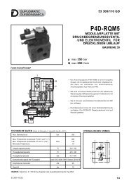
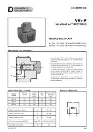
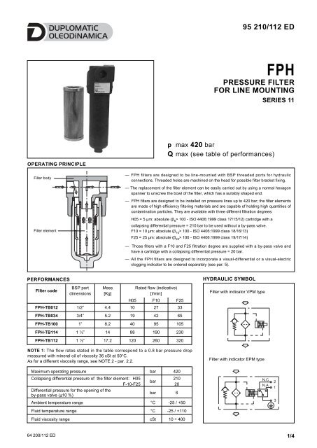
OPERATING PRINCIPLE<br />
Filter body<br />
Filter element<br />
PERFORMANCES<br />
Filter code<br />
BSP port<br />
dimensions<br />
Mass<br />
[Kg]<br />
NOTE 1: The flow rates stated in the table correspond to a 0.8 bar pressure drop<br />
measured with mineral oil of viscosity 36 cSt at 50°C.<br />
As for a different viscosity range, see NOTE 2 - par. 2.2.<br />
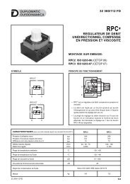
<strong>FPH</strong><br />
PRESSURE FILTER<br />
FOR LINE MOUNTING<br />
SERIES 11<br />
— <strong>FPH</strong> filters are designed to be line-mounted with BSP threaded ports for hydraulic<br />
connections. Threaded holes are machined on the head for possible filter bracket fixing.<br />
— The replacement of the filter element can be easily carried out by using a normal hexagon<br />
spanner to unscrew the bowl of the filter, which has a suitably shaped end.<br />
— <strong>FPH</strong> filters are designed to be installed on pressure lines up to 420 bar; the filter elements<br />
are made of high efficiency filtering materials and are capable of holding high quantities of<br />
contamination particles. They are available with three different filtration degrees:<br />
H05 = 5 µm: absolute (β5 > 100 - ISO 4406:1999 class 17/15/12) cartridge with a<br />
collapsing differential pressure = 210 bar to be used without a by-pass valve.<br />
F10 = 10 µm: absolute (β10 > 100 - ISO 4406:1999 class 18/16/13)<br />
F25 = 25 µm: absolute (β25 > 100 - ISO 4406:1999 class 19/17/14)<br />
— Those filters with a F10 and F25 filtration degree are supplied with a by-pass valve and<br />
have a cartridge with a collapsing differential pressure = 20 bar.<br />
— All the <strong>FPH</strong> filters are designed to incorporate a visual-differential or a visual-electric<br />
clogging indicator to be ordered separately (see par. 5).<br />
Rated flow (indicative)<br />
[l/min]<br />
H05 F10 F25<br />
<strong>FPH</strong>-TB012 1/2” 4.4 10 27 33<br />
<strong>FPH</strong>-TB034 3/4” 5.2 19 42 65<br />
<strong>FPH</strong>-TB100 1” 8.2 40 95 105<br />
<strong>FPH</strong>-TB114 1 ¼” 14 88 190 230<br />
<strong>FPH</strong>-TB112 1 ½” 17.2 120 260 320<br />
Maximum operating pressure bar 420<br />
Collapsing differential pressure of the filter element: H05<br />
F-10-F25<br />
Differential pressure for the opening of the<br />
by-pass valve (±10 %)<br />
bar<br />
HYDRAULIC SYMBOL<br />
Filter with indicator VPM type<br />
Filter with indicator EPM type<br />
95 210/112 ED<br />
p max 420 bar<br />
Q max (see table of performances)<br />
64 200/112 ED 1/4<br />
210<br />
20<br />
bar 6<br />
Ambient temperature range °C -25 / +50<br />
Fluid temperature range °C -25 / +110<br />
Fluid viscosity range cSt 10 ÷ 400
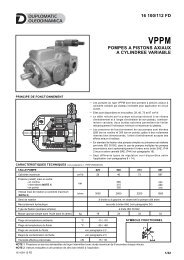
1 - IDENTIFICATION CODE<br />
F P H - T B - S / 11 -<br />
High pressure delivery<br />
filter<br />
BSP threaded ports<br />
Nominal dimension:<br />
012 = 1/2” 100 = 1” 112 = 1 1/2”<br />
034 = 3/4” 114 = 1 1/4”<br />
Filtration degree: H05 = fibre 5 µm (β 5 > 100) - ISO 4406:1999 class 17/15/12<br />
F10 = fibre 10 µm (β 10 > 100) - ISO 4406:1999 class 18/16/13<br />
F25 = fibre 25 µm (β 25 > 100) - ISO 4406:1999 class 19/17/14<br />
Standard filter element<br />
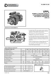
2 - CHARACTERISTIC CURVES (values measured with viscosity of 36 cSt at 50°C)<br />
2.1 - Pressure drops through the filter body<br />
2.2 - Pressure drops through the <strong>FPH</strong>E filter element<br />
<strong>FPH</strong><br />
SERIES 11<br />
B = with by-pass valve<br />
Opening pressure: 6 bar<br />
0 = without by-pass valve<br />
(compulsory for a H05<br />
filtration degree)<br />
Seals:<br />
N = NBR standard seals for<br />
mineral oils (standard)<br />
V = FPM seals for special fluids<br />
Series No. (from 10 to 19 sizes and<br />
mounting dimensions remain<br />
unchanged)<br />
<strong>FPH</strong>E-TB012 <strong>FPH</strong>E-TB034 <strong>FPH</strong>E-TB100<br />
<strong>FPH</strong>E-TB114 <strong>FPH</strong>E-TB112<br />
64 200/112 ED 2/4
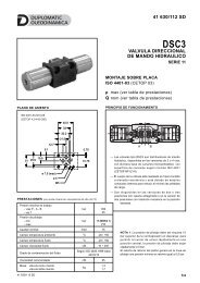
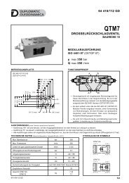
4 - OVERALL AND MOUNTING DIMENSIONS<br />
dimensions in mm<br />
<strong>FPH</strong><br />
SERIES 11<br />
NOTE 2: The filter size has to be selected so that with the nominal flow rate the pressure drop is lower than 0.8 bar.<br />
The total pressure drop through the filter is given by adding the body pressure drop values to those of the filter element. As for fluids whose<br />
viscosity degree at a specific operating pressure is different from 36 cSt, the filter total pressure drop has to be changed according to the<br />
following ratio:<br />
total ∆pl value = body ∆p value + (real ∆p value of the filter element x real viscosity value (cSt) / 36)<br />
real ∆p value of the filter element = value obtainable through the diagrams in par. 2.2<br />
Such ratio is valid for a viscosity value up to 200 cSt. For a higher viscosity please consult our technical department.<br />
2.3 - Pressure drops through the by-pass valve<br />
<strong>FPH</strong>-TB012 <strong>FPH</strong>-TB114<br />
<strong>FPH</strong>-TB034 <strong>FPH</strong>-TB100 <strong>FPH</strong>-TB112<br />
3 - HYDRAULIC FLUIDS<br />
Use mineral oil-based hydraulic fluids HL or HM type, according to ISO 6743-4. For these fluids, use NBR seals. For fluids HFDR type<br />
(phosphate esters) use FPM seals (code V). For the use of other kinds of fluid such as HFA, HFB, HFC, please consult our technical<br />
department. Using fluids at temperatures higher than 80 °C causes a faster degradation of the fluid and of the seals characteristics.<br />
The fluid must be preserved in its physical and chemical characteristics.<br />
SW 30<br />
filter D1 D2 H1 H2 H3 H4 H5 L1 L2 L3 L4 R*<br />
<strong>FPH</strong>- TB012 1/2” 82 166 79 86 23 63 85 46 M8 12,5 100<br />
<strong>FPH</strong>- TB034 3/4” 82 296 209 86 23 63 85 46 M8 12,5 100<br />
<strong>FPH</strong>- TB100 1” 94 317 207 112 35 77 107 65 M8 - 100<br />
<strong>FPH</strong>- TB114 1 ¼” 128 337 199 137 44 93 143 88 M10 43 100<br />
<strong>FPH</strong>- TB112 1 ½” 128 457 319 137 44 93 143 88 M10 43 100<br />
R* = removal space for filter element<br />
<strong>FPH</strong> - TB012<br />
<strong>FPH</strong> - TB034<br />
<strong>FPH</strong> - TB100<br />
<strong>FPH</strong> - TB114<br />
<strong>FPH</strong> - TB112<br />
64 200/112 ED 3/4<br />
1<br />
Clogging indicator port:<br />
M20 x 1,5
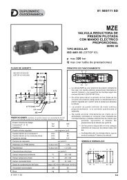
5 - CLOGGING INDICATORS<br />
The filters are all designed to incorporate clogging indicators, which<br />
have to be ordered separately.<br />
5.1 - Visual indicator for delivery filters<br />
Identification code: VPM/10<br />
This indicator measures the<br />
differential pressure between the<br />
filter input and output.<br />
The indicator is supplied with<br />
coloured bands, which informs you<br />
about the clogging condition of the<br />
filter element:<br />
WHITE: efficient filter element ∆p 5 bar (± 10%)<br />
5.2 - Electric-visual indicator for delivery filters<br />
Identification code: EPM/10<br />
TECHNICAL SPECIFICATIONS<br />
This indicator, apart from giving<br />
a visual indication, for example<br />
the VPM model, operates by<br />
switching an electric contact<br />
when the filter element has<br />
reached the clogging limit.<br />
The contact can be wired in an<br />
open or closed condition (see<br />
the hydraulic symbol).<br />
Differential operating pressure bar 5<br />
AC power supply<br />
Max. operating voltage VAC 250 50/60 Hz<br />
Max. load on the contacts<br />
(inductive or resistive)<br />
DC power supply<br />
A 1<br />
Max. operating voltage VDC 125<br />
Max. load on the contacts<br />
(with V at 30-50-75-125 VDC)<br />
resistive<br />
inductive<br />
DUPLOMATIC OLEODINAMICA S.p.A.<br />
20015 PARABIAGO (MI) • Via M. Re Depaolini 24<br />
Tel. +39 0331.895.111<br />
Fax +39 0331.895.339<br />
www.duplomatic.com • e-mail: sales.exp@duplomatic.com<br />
A<br />
2 - 0,5 - 0,25 - 0,2<br />
2 - 0,5 - 0,25 - 0,03<br />
Electric connector DIN 43650<br />
Class of protection according to<br />
CEI EN 60529 (atmospheric agents)<br />
IP65<br />
6 - FILTER ELEMENTS<br />
filter element<br />
code<br />
FILTER ELEMENT IDENTIFICATION CODE<br />
Nominal dimension:<br />
012 = 1/2” 114 = 1 1/4”<br />
034 = 3/4” 112 = 1 1/2”<br />
100 = 1”<br />
<strong>FPH</strong><br />
SERIES 11<br />
F P H E - - S / 10<br />
Filter element for<br />
<strong>FPH</strong> filters<br />
ØA ØB C<br />
Filtration degree: H05 = fibre 5 µm<br />
F10 = fibre 10 µm<br />
F25 = fibre 25 µm<br />
Standard filter element<br />
Average filtering<br />
surface [cm²]<br />
H05 F12/F25<br />
<strong>FPH</strong>E - 012 45 25 85 340 355<br />
<strong>FPH</strong>E - 034 45 25 211 915 935<br />
<strong>FPH</strong>E - 100 52 23,5 210 1785 1830<br />
<strong>FPH</strong>E - 114 78 42,5 210 2695 3695<br />
<strong>FPH</strong>E - 112 78 42,5 330 4325 5025<br />
Series N. (from 10 to 19<br />
sizes and mounting<br />
dimensions remain unchanged)<br />
N = NBR seals for mineral oils (standard)<br />
V = FPM seals for special fluids (upon request)<br />
64 200/112 ED REPRODUCTION IS FORBIDDEN. THE COMPANY RESERVES THE RIGHT TO APPLY ANY MODIFICATIONS.<br />
4/4